2008 NISSAN TIIDA harness layout
[x] Cancel search: harness layoutPage 83 of 2771
TROUBLE DIAGNOSIS
AT-71
< SERVICE INFORMATION >
D
E
F
G
H
I
J
K
L
MA
B
AT
N
O
P
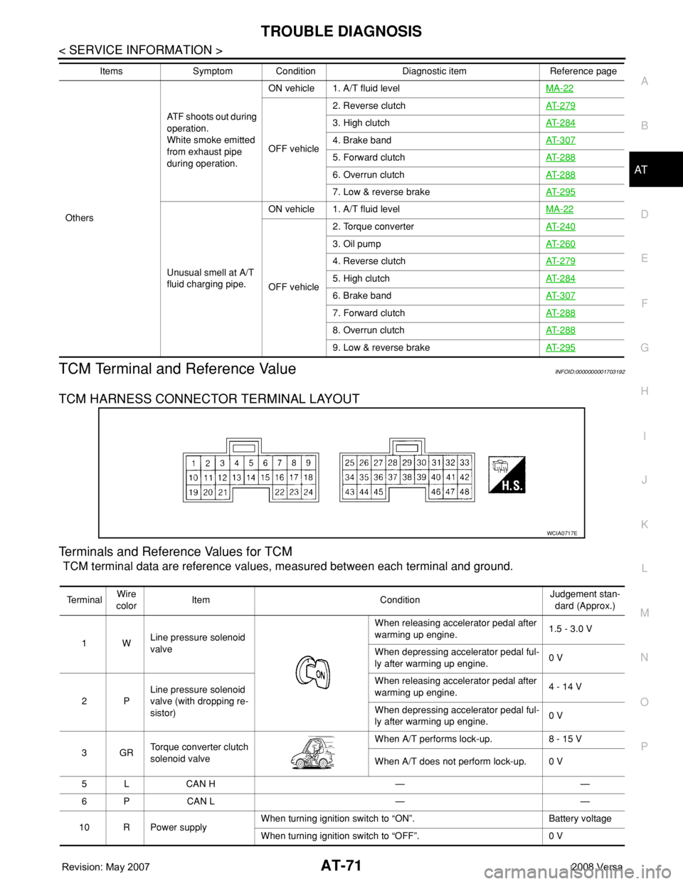
TCM Terminal and Reference ValueINFOID:0000000001703192
TCM HARNESS CONNECTOR TERMINAL LAYOUT
Terminals and Reference Values for TCM
TCM terminal data are reference values, measured between each terminal and ground.
OthersATF shoots out during
operation.
White smoke emitted
from exhaust pipe
during operation.ON vehicle 1. A/T fluid levelMA-22
OFF vehicle2. Reverse clutchAT- 2 7 9
3. High clutchAT- 2 8 4
4. Brake bandAT- 3 0 7
5. Forward clutchAT- 2 8 8
6. Overrun clutchAT- 2 8 8
7. Low & reverse brakeAT- 2 9 5
Unusual smell at A/T
fluid charging pipe.ON vehicle 1. A/T fluid levelMA-22
OFF vehicle2. Torque converterAT- 2 4 0
3. Oil pumpAT- 2 6 0
4. Reverse clutchAT- 2 7 9
5. High clutchAT- 2 8 4
6. Brake bandAT- 3 0 7
7. Forward clutchAT- 2 8 8
8. Overrun clutchAT- 2 8 8
9. Low & reverse brakeAT- 2 9 5
Items Symptom Condition Diagnostic item Reference page
WCIA0717E
Te r m i n a lWire
colorItem ConditionJudgement stan-
dard (Approx.)
1WLine pressure solenoid
valveWhen releasing accelerator pedal after
warming up engine.1.5 - 3.0 V
When depressing accelerator pedal ful-
ly after warming up engine.0 V
2PLine pressure solenoid
valve (with dropping re-
sistor)When releasing accelerator pedal after
warming up engine.4 - 14 V
When depressing accelerator pedal ful-
ly after warming up engine.0 V
3GRTorque converter clutch
solenoid valveWhen A/T performs lock-up. 8 - 15 V
When A/T does not perform lock-up. 0 V
5 L CAN H — —
6 P CAN L — —
10 R Power supplyWhen turning ignition switch to “ON”. Battery voltage
When turning ignition switch to “OFF”. 0 V
Page 360 of 2771
AV-1
ELECTRICAL
C
D
E
F
G
H
I
J
L
M
SECTION AV
A
B
AV
N
O
P
CONTENTS
AUDIO, VISUAL, NAVIGATION & TELEPHONE SYS-
TEM
SERVICE INFORMATION ............................2
PRECAUTIONS ...................................................2
Precaution for Supplemental Restraint System
(SRS) "AIR BAG" and "SEAT BELT PRE-TEN-
SIONER" ...................................................................
2
PREPARATION ...................................................3
Commercial Service Tool ..........................................3
AUDIO .................................................................4
Component Parts Location ........................................4
System Description ...................................................4
Schematic .................................................................6
Wiring Diagram - AUDIO - .........................................8
Audio Unit (Base System) Harness Connector
Terminal Layout ......................................................
15
Terminal and Reference Value for Audio Unit
(Base System) .........................................................
15
Audio Unit (Mid Level and Premium System) Har-
ness Connector Terminal Layout ............................
16
Terminal and Reference Value for Audio Unit (Mid
Level and Premium System) ...................................
16
Subwoofer Harness Connector Terminal Layout
(Premium Audio System) ........................................
19
Terminal and Reference Value for Subwoofer
(Premium Audio System) ........................................
19
Satellite Radio Tuner Harness Connector Termi-
nal Layout ................................................................
19
Terminal and Reference Value for Satellite Radio
Tuner .......................................................................
20
Trouble Diagnosis ...................................................20
Noise Inspection ......................................................21
Power Supply Circuit Inspection .............................22
Satellite Radio Tuner (Factory Installed) Power
and Ground Supply Circuit Inspection .....................
23
Satellite Radio Tuner (Factory Installed) Commu-
nication Circuit Inspection .......................................
24
Satellite Radio Tuner (Factory Installed) Left
Channel Audio Signal Circuit Inspection .................
26
Satellite Radio Tuner (Factory Installed) Right
Channel Audio Signal Circuit Inspection .................
26
Steering Switch Check (With Bluetooth) ..................27
Sound Is Not Heard from Front Door Speaker
(Base System) .........................................................
29
Sound Is Not Heard from Rear Door Speaker
(Base System) .........................................................
30
Sound Is Not Heard from Front Door Speaker or
Tweeter (Mid Level and Premium System) .............
31
Sound Is Not Heard from Rear Door Speaker (Mid
Level and Premium System) ...................................
32
Sound Is Not Heard from Subwoofer (Premium
System) ...................................................................
34
Removal and Installation .........................................36
AUDIO ANTENNA .............................................41
Location of Antenna .................................................41
Removal and Installation of Roof Antenna ..............41
TELEPHONE .....................................................43
Component Parts and Harness Connector Loca-
tion ...........................................................................
43
System Description ..................................................43
Wiring Diagram - H/PHON - ....................................45
Bluetooth Control Unit Harness Connector Termi-
nal Layout ................................................................
47
Terminal and Reference Value for Bluetooth Con-
trol Unit ....................................................................
47
Bluetooth Control Unit Self-Diagnosis Function ......48
Workflow ..................................................................49
Power Supply and Ground Circuit Inspection for
Bluetooth Control Unit .............................................
49
Basic Inspection of Hands-Free Phone ...................50
Steering Wheel Audio Control Switch Does Not
Operate ....................................................................
51
Voice Activated Control Function Does Not Oper-
ate ............................................................................
52
Removal and Installation .........................................54
Page 374 of 2771
AUDIO
AV-15
< SERVICE INFORMATION >
C
D
E
F
G
H
I
J
L
MA
B
AV
N
O
P
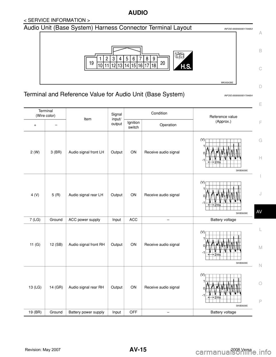
Audio Unit (Base System) Harness Connector Terminal LayoutINFOID:0000000001704653
Terminal and Reference Value for Audio Unit (Base System)INFOID:0000000001704654
WKIA5439E
Te r m i n a l
(Wire color)
ItemSignal
input/
outputCondition
Reference value
(Approx.)
+–Ignition
switchOperation
2 (W) 3 (BR) Audio signal front LH Output ON Receive audio signal
4 (V) 5 (R) Audio signal rear LH Output ON Receive audio signal
7 (LG) Ground ACC power supply Input ACC – Battery voltage
11 (G) 12 (SB) Audio signal front RH Output ON Receive audio signal
13 (LG) 14 (GR) Audio signal rear RH Output ON Receive audio signal
19 (BR) Ground Battery power supply Input OFF – Battery voltage
SKIB3609E
SKIB3609E
SKIB3609E
SKIB3609E
Page 375 of 2771
AV-16
< SERVICE INFORMATION >
AUDIO
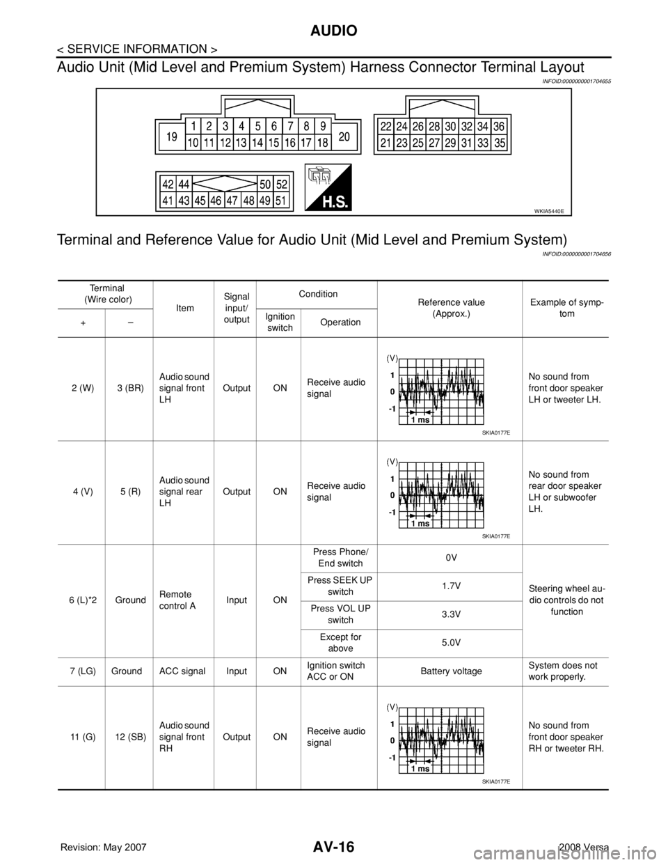
Audio Unit (Mid Level and Premium System) Harness Connector Terminal Layout
INFOID:0000000001704655
Terminal and Reference Value for Audio Unit (Mid Level and Premium System)
INFOID:0000000001704656
WKIA5440E
Te r m i n a l
(Wire color)
ItemSignal
input/
outputCondition
Reference value
(Approx.)Example of symp-
tom
+–Ignition
switchOperation
2 (W) 3 (BR)Audio sound
signal front
LHOutput ONReceive audio
signalNo sound from
front door speaker
LH or tweeter LH.
4 (V) 5 (R)Audio sound
signal rear
LHOutput ONReceive audio
signalNo sound from
rear door speaker
LH or subwoofer
LH.
6 (L)*2 GroundRemote
control AInput ONPress Phone/
End switch0V
Steering wheel au-
dio controls do not
function Press SEEK UP
switch1.7V
Press VOL UP
switch3.3V
Except for
above5.0V
7 (LG) Ground ACC signal Input ONIgnition switch
ACC or ONBattery voltageSystem does not
work properly.
11 (G) 12 (SB)Audio sound
signal front
RHOutput ONReceive audio
signalNo sound from
front door speaker
RH or tweeter RH.
SKIA0177E
SKIA0177E
SKIA0177E
Page 378 of 2771
AUDIO
AV-19
< SERVICE INFORMATION >
C
D
E
F
G
H
I
J
L
MA
B
AV
N
O
P
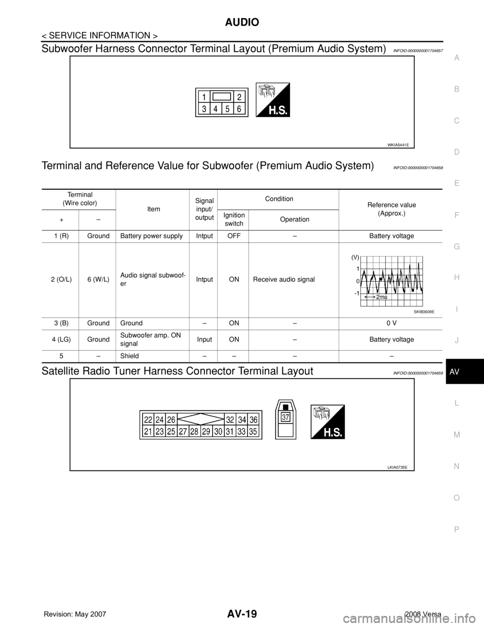
Subwoofer Harness Connector Terminal Layout (Premium Audio System)INFOID:0000000001704657
Terminal and Reference Value for Subwoofer (Premium Audio System)INFOID:0000000001704658
Satellite Radio Tuner Harness Connector Terminal LayoutINFOID:0000000001704659
WKIA5441E
Te r m i n a l
(Wire color)
ItemSignal
input/
outputCondition
Reference value
(Approx.)
+–Ignition
switchOperation
1 (R) Ground Battery power supply Intput OFF – Battery voltage
2 (O/L) 6 (W/L)Audio signal subwoof-
erIntput ON Receive audio signal
3 (B) Ground Ground – ON – 0 V
4 (LG) GroundSubwoofer amp. ON
signalInput ON – Battery voltage
5–Shield –– – –
SKIB3609E
LKIA0735E
Page 406 of 2771
TELEPHONE
AV-47
< SERVICE INFORMATION >
C
D
E
F
G
H
I
J
L
MA
B
AV
N
O
P
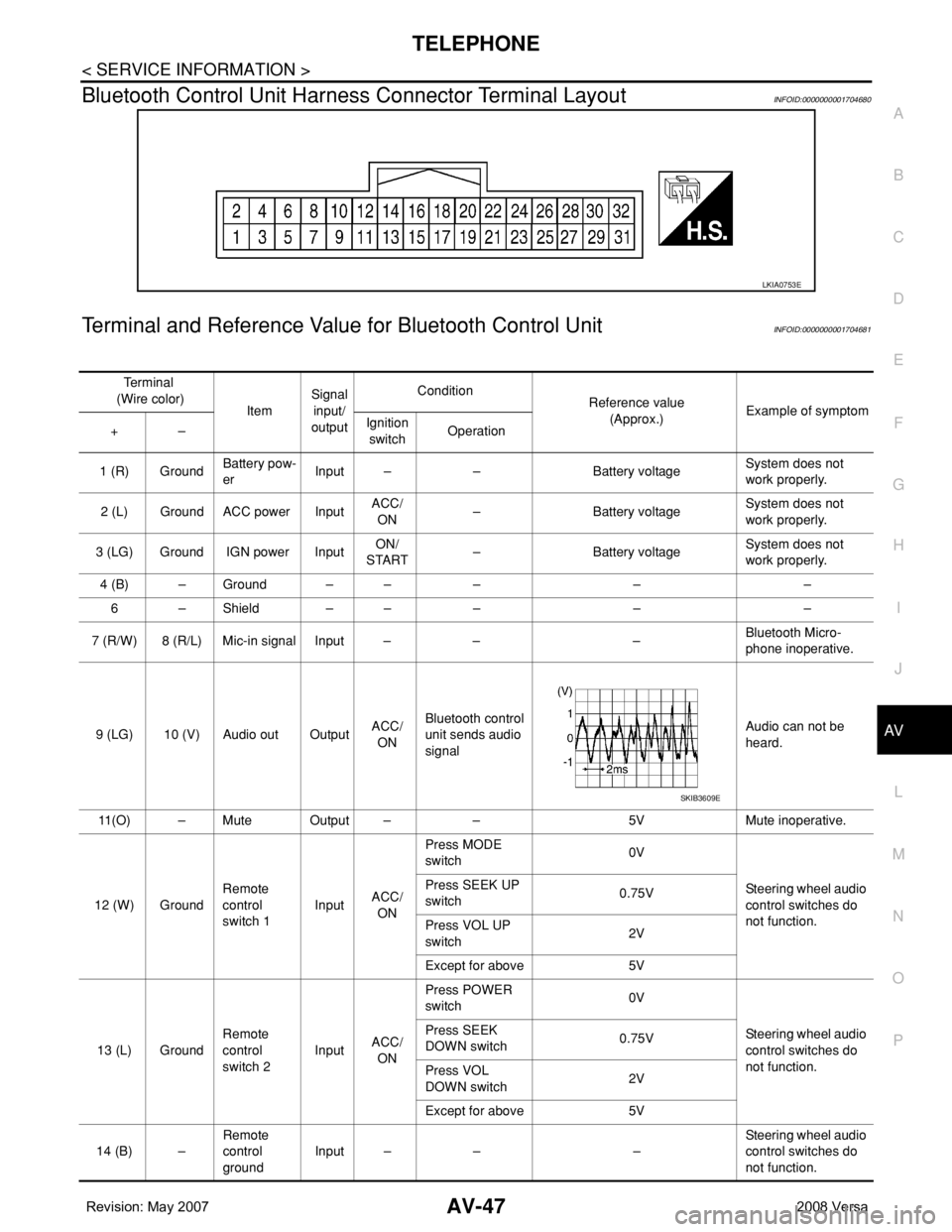
Bluetooth Control Unit Harness Connector Terminal LayoutINFOID:0000000001704680
Terminal and Reference Value for Bluetooth Control UnitINFOID:0000000001704681
LKIA0753E
Te r m i n a l
(Wire color)
ItemSignal
input/
outputCondition
Reference value
(Approx.)Example of symptom
+–Ignition
switchOperation
1 (R) GroundBattery pow-
erInput – – Battery voltageSystem does not
work properly.
2 (L) Ground ACC power InputACC/
ON– Battery voltageSystem does not
work properly.
3 (LG) Ground IGN power InputON/
START– Battery voltageSystem does not
work properly.
4 (B) – Ground – – – – –
6 – Shield – – – – –
7 (R/W) 8 (R/L) Mic-in signal Input – – –Bluetooth Micro-
phone inoperative.
9 (LG) 10 (V) Audio out OutputACC/
ONBluetooth control
unit sends audio
signalAudio can not be
heard.
11(O) – Mute Output – – 5V Mute inoperative.
12 (W) GroundRemote
control
switch 1InputACC/
ONPress MODE
switch 0V
Steering wheel audio
control switches do
not function. Press SEEK UP
switch0.75V
Press VOL UP
switch2V
Except for above 5V
13 (L) GroundRemote
control
switch 2InputACC/
ONPress POWER
switch 0V
Steering wheel audio
control switches do
not function. Press SEEK
DOWN switch0.75V
Press VOL
DOWN switch2V
Except for above 5V
14 (B) –Remote
control
groundInput – – –Steering wheel audio
control switches do
not function.
SKIB3609E
Page 436 of 2771

BL-2
ID Code Entry Procedure .......................................71
Keyfob Battery Replacement ..................................73
Removal and Installation of Remote Keyless Entry
Receiver .................................................................
73
INTELLIGENT KEY SYSTEM ............................74
Component Parts and Harness Connector Loca-
tion ..........................................................................
74
System Description .................................................76
CAN Communication System Description ..............83
Schematic ...............................................................84
Wiring Diagram - I/KEY - ........................................86
Intelligent Key Unit Harness Connector Terminal
Layout .....................................................................
96
Terminal and Reference Value for Intelligent Key
Unit .........................................................................
96
Steering Lock Solenoid Harness Connector Ter-
minal Layout ...........................................................
98
Terminal and Reference Value for Steering Lock
Solenoid ..................................................................
98
Terminal and Reference Value for BCM .................99
Trouble Diagnosis Procedure .................................99
CONSULT-III Functions (INTELLIGENT KEY) ......100
CONSULT-III Application Item ...............................101
Trouble Diagnosis Symptom Chart ........................103
CAN Communication System Inspection ...............109
Power Supply and Ground Circuit Inspection ........110
Key Switch (Intelligent Key Unit Input) Check .......110
Key Switch (BCM Input) Check .............................112
Ignition Knob Switch Check ...................................113
Door Switch Check (Hatchback) ............................114
Door Switch Check (Sedan) ..................................117
Door Request Switch Check ..................................118
Back Door Request Switch Check (Hatchback) ....120
Trunk Opener Request Switch Check (Sedan) .....122
Unlock Sensor Check ............................................124
Intelligent Key Warning Buzzer(s) Check ..............125
Outside Key Antenna (Driver Side and Passenger
Side) Check ...........................................................
126
Outside Key Antenna (Rear Bumper) Check .........128
Inside Key Antenna Check ....................................129
Steering Lock Solenoid Check ..............................131
Key Interlock Solenoid (With M/T) Check ..............133
Ignition Switch Position Check ..............................134
Stop Lamp Switch Check (With CVT) ....................134
Stop Lamp Switch Check (With M/T) .....................135
Check CVT Device (Park Position Switch) Check ..136
"P-SHIFT" Warning Lamp (With CVT) Check ........138
"LOCK" Warning Lamp (With M/T) Check .............138
"KEY" Warning Lamp (RED) Check ......................139
"KEY" Warning Lamp (GREEN) Check .................139
Check Warning Chime in Combination Meter ........140
Hazard Function Check .........................................140
Horn Function Check .............................................140
Headlamp Function Check ....................................141
Intelligent Key Battery Replacement .....................142
Remote Keyless Entry Function ............................142
Removal and Installation of Intelligent Key Unit ....142
DOOR ...............................................................144
Fitting Adjustment .................................................144
Removal and Installation .......................................147
FRONT DOOR LOCK .......................................150
Component Parts Location ...................................150
Removal and Installation .......................................150
REAR DOOR LOCK .........................................153
Component Parts Location ...................................153
Removal and Installation .......................................153
BACK DOOR LOCK .........................................156
Component Parts and Harness Connector Loca-
tion ........................................................................
156
System Description ...............................................156
Wiring Diagram - B/DOOR - ..................................157
Terminal and Reference Value for BCM ...............158
Terminal and Reference Value for Intelligent Key
Unit ........................................................................
158
CONSULT-III Function (BCM) ..............................159
Work Flow .............................................................159
Trouble Diagnosis Chart by Symptom ..................159
BCM Power Supply and Ground Circuit ................160
Check Back Door Opener Switch Circuit (Without
Intelligent Key or Power Windows) .......................
160
Check Back Door Opener Switch Circuit (Without
Intelligent Key, with Power Windows) ...................
162
Check Back Door Opener Switch Circuit (With In-
telligent Key) .........................................................
165
Check Back Door Lock Assembly (Actuator) Cir-
cuit ........................................................................
166
Removal and Installation .......................................168
TRUNK LID .......................................................170
Fitting Adjustment .................................................170
Trunk Lid Assembly ..............................................170
Trunk Lid Lock ......................................................171
Trunk Lid Striker ....................................................171
TRUNK LID OPENER .......................................173
Component Parts and Harness Connector Loca-
tion ........................................................................
173
System Description ...............................................173
Wiring Diagram - TLID - ........................................174
Terminal and Reference Value for BCM ...............175
Terminal and Reference Value for Intelligent Key
Unit ........................................................................
175
CONSULT-III Function (BCM) ..............................176
Work Flow .............................................................176
Trouble Diagnosis Chart by Symptom ..................176
BCM Power Supply and Ground Circuit ................177
Check Trunk Lid Opener Switch Circuit (Without
Intelligent Key or Power Windows) .......................
177
Check Trunk Lid Opener Switch Circuit (Without
Intelligent Key, with Power Windows) ...................
179
Check Trunk Lid Opener Switch Circuit (With Intel-
ligent Key) .............................................................
182
Check Trunk Release Solenoid Circuit .................183
Page 530 of 2771
BL-96
< SERVICE INFORMATION >
INTELLIGENT KEY SYSTEM
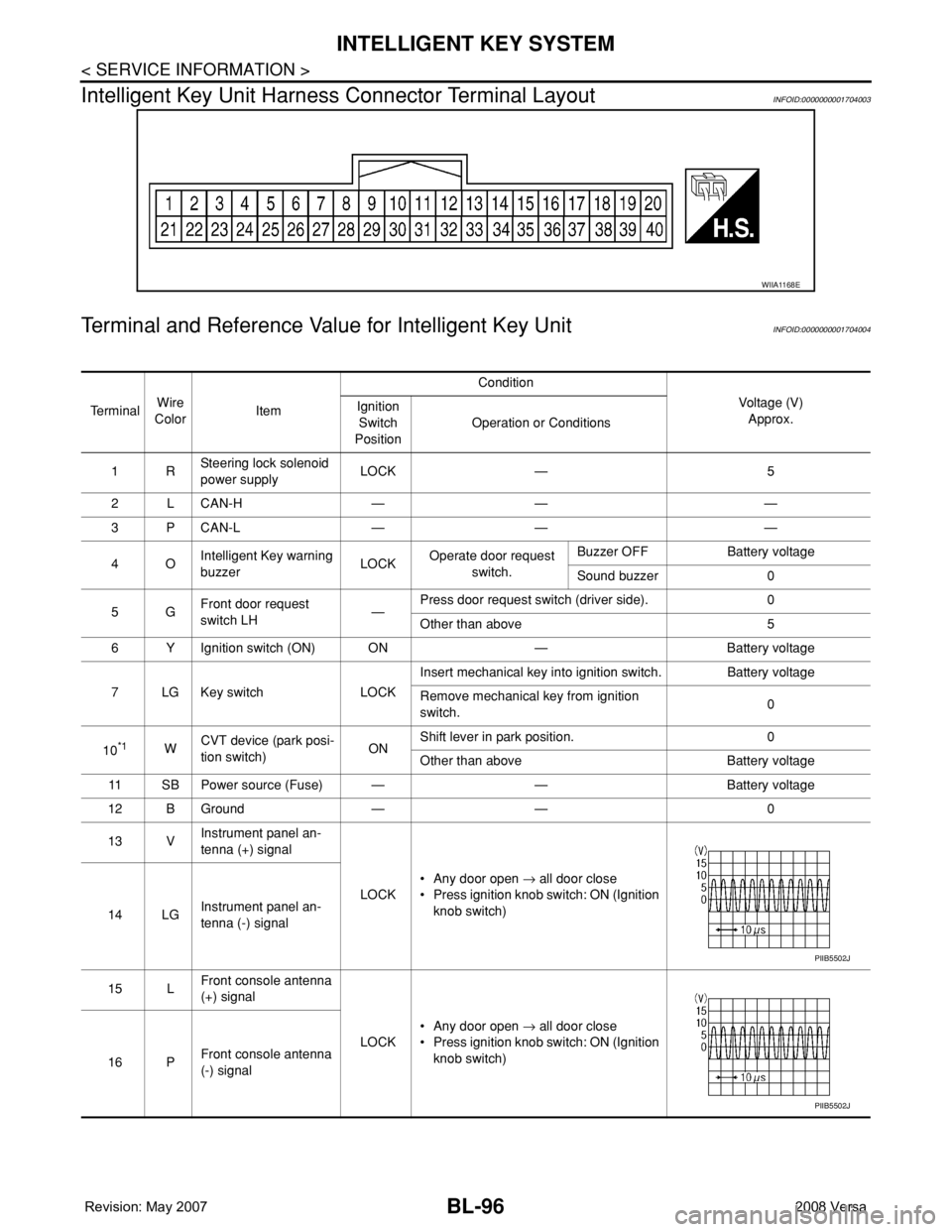
Intelligent Key Unit Harness Connector Terminal Layout
INFOID:0000000001704003
Terminal and Reference Value for Intelligent Key UnitINFOID:0000000001704004
WIIA1168E
Te r m i n a lWire
ColorItemCondition
Voltage (V)
Approx. Ignition
Switch
PositionOperation or Conditions
1RSteering lock solenoid
power supplyLOCK — 5
2 L CAN-H — — —
3 P CAN-L — — —
4OIntelligent Key warning
buzzerLOCKOperate door request
switch.Buzzer OFF Battery voltage
Sound buzzer 0
5GFront door request
switch LH—Press door request switch (driver side). 0
Other than above 5
6 Y Ignition switch (ON) ON — Battery voltage
7 LG Key switch LOCKInsert mechanical key into ignition switch. Battery voltage
Remove mechanical key from ignition
switch.0
10
*1WCVT device (park posi-
tion switch)ONShift lever in park position. 0
Other than above Battery voltage
11 SB Power source (Fuse) — — Battery voltage
12 B Ground — — 0
13 VInstrument panel an-
tenna (+) signal
LOCK• Any door open → all door close
• Press ignition knob switch: ON (Ignition
knob switch)
14 LGInstrument panel an-
tenna (-) signal
15 LFront console antenna
(+) signal
LOCK• Any door open → all door close
• Press ignition knob switch: ON (Ignition
knob switch)
16 PFront console antenna
(-) signal
PIIB5502J
PIIB5502J