2008 NISSAN TIIDA ASSEMBLE
[x] Cancel search: ASSEMBLEPage 138 of 2771
AT-126
< SERVICE INFORMATION >
DTC P0744 A/T TCC S/V FUNCTION (LOCK-UP)
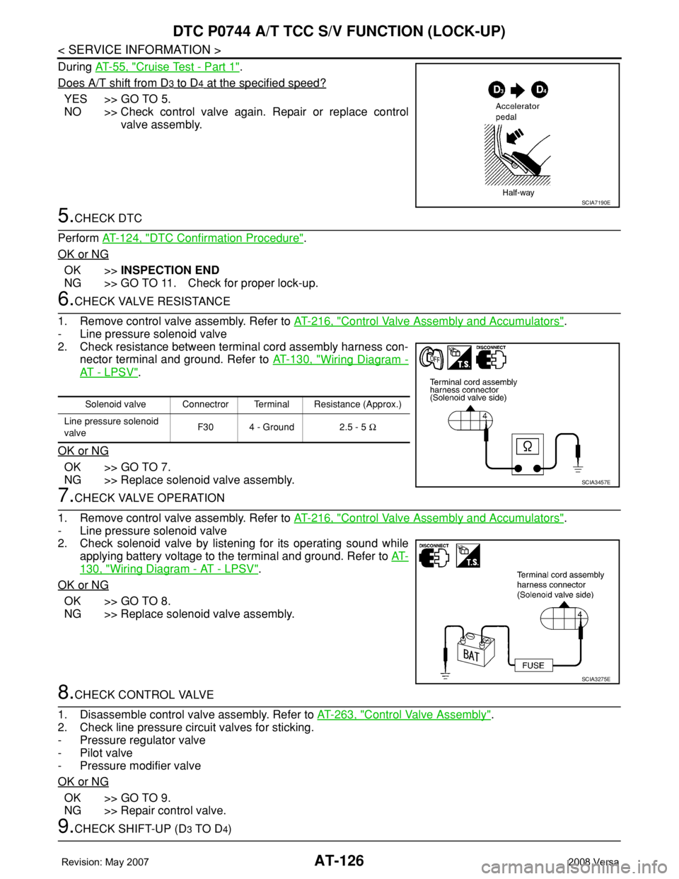
During AT-55, "Cruise Test - Part 1".
Does A/T shift from D
3 to D4 at the specified speed?
YES >> GO TO 5.
NO >> Check control valve again. Repair or replace control
valve assembly.
5.CHECK DTC
Perform AT-124, "
DTC Confirmation Procedure".
OK or NG
OK >>INSPECTION END
NG >> GO TO 11. Check for proper lock-up.
6.CHECK VALVE RESISTANCE
1. Remove control valve assembly. Refer to AT-216, "
Control Valve Assembly and Accumulators".
- Line pressure solenoid valve
2. Check resistance between terminal cord assembly harness con-
nector terminal and ground. Refer to AT-130, "
Wiring Diagram -
AT - L P S V".
OK or NG
OK >> GO TO 7.
NG >> Replace solenoid valve assembly.
7.CHECK VALVE OPERATION
1. Remove control valve assembly. Refer to AT-216, "
Control Valve Assembly and Accumulators".
- Line pressure solenoid valve
2. Check solenoid valve by listening for its operating sound while
applying battery voltage to the terminal and ground. Refer to AT-
130, "Wiring Diagram - AT - LPSV".
OK or NG
OK >> GO TO 8.
NG >> Replace solenoid valve assembly.
8.CHECK CONTROL VALVE
1. Disassemble control valve assembly. Refer to AT-263, "
Control Valve Assembly".
2. Check line pressure circuit valves for sticking.
- Pressure regulator valve
- Pilot valve
- Pressure modifier valve
OK or NG
OK >> GO TO 9.
NG >> Repair control valve.
9.CHECK SHIFT-UP (D3 TO D4)
SCIA7190E
Solenoid valve Connectror Terminal Resistance (Approx.)
Line pressure solenoid
valveF30 4 - Ground 2.5 - 5 Ω
SCIA3457E
SCIA3275E
Page 140 of 2771
AT-128
< SERVICE INFORMATION >
DTC P0744 A/T TCC S/V FUNCTION (LOCK-UP)
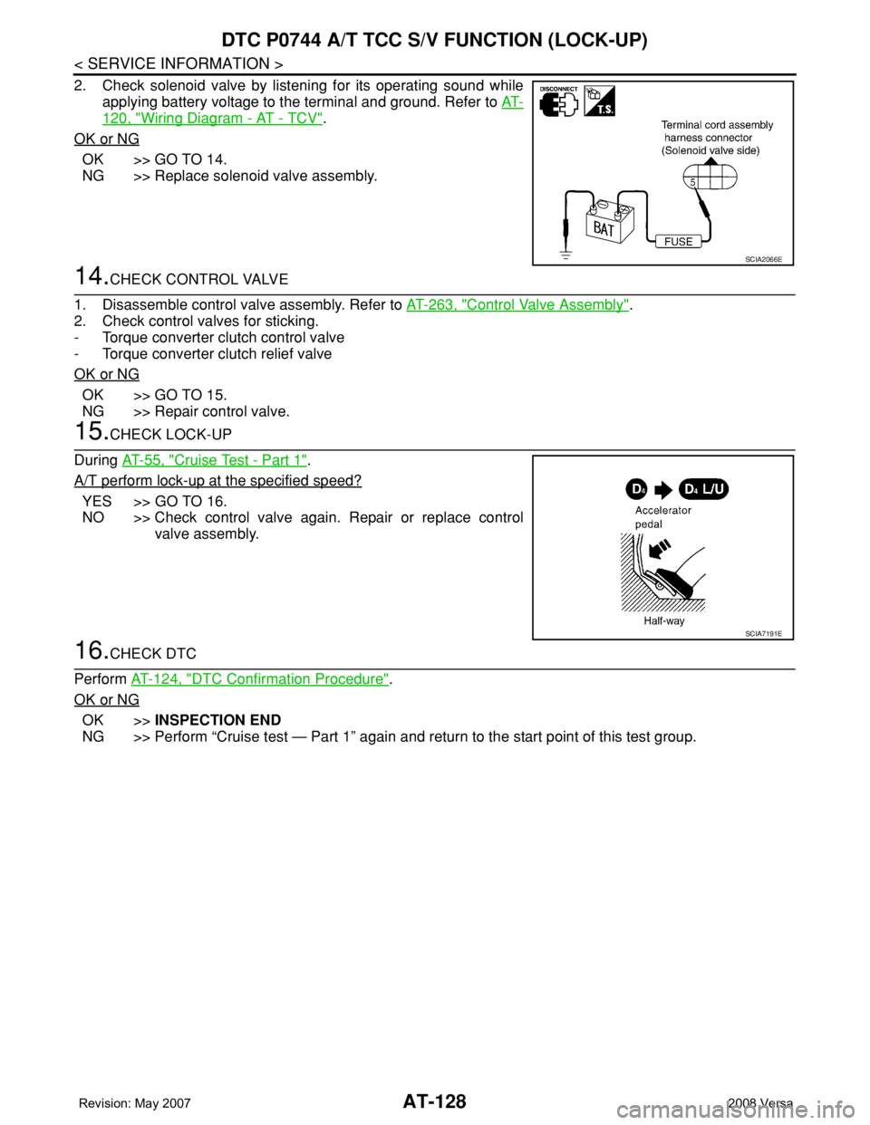
2. Check solenoid valve by listening for its operating sound while
applying battery voltage to the terminal and ground. Refer to AT-
120, "Wiring Diagram - AT - TCV".
OK or NG
OK >> GO TO 14.
NG >> Replace solenoid valve assembly.
14.CHECK CONTROL VALVE
1. Disassemble control valve assembly. Refer to AT-263, "
Control Valve Assembly".
2. Check control valves for sticking.
- Torque converter clutch control valve
- Torque converter clutch relief valve
OK or NG
OK >> GO TO 15.
NG >> Repair control valve.
15.CHECK LOCK-UP
During AT-55, "
Cruise Test - Part 1".
A/T perform lock-up at the specified speed?
YES >> GO TO 16.
NO >> Check control valve again. Repair or replace control
valve assembly.
16.CHECK DTC
Perform AT-124, "
DTC Confirmation Procedure".
OK or NG
OK >>INSPECTION END
NG >> Perform “Cruise test — Part 1” again and return to the start point of this test group.
SCIA2066E
SCIA7191E
Page 192 of 2771
AT-180
< SERVICE INFORMATION >
TROUBLE DIAGNOSIS FOR SYMPTOMS
OK or NG
OK >> GO TO 5.
NG >> GO TO 4.
4.DETECT MALFUNCTIONING ITEM
1. Disassemble A/T. Refer to AT-240, "
Disassembly" .
2. Check the following items:
- Forward clutch assembly. Refer to AT-288, "
Forward and Overrun Clutches" .
- Overrun clutch assembly. Refer to AT-288, "
Forward and Overrun Clutches" .
- Reverse clutch assembly. Refer to AT-279, "
Reverse Clutch" .
OK or NG
OK >> GO TO 5.
NG >> Repair or replace damaged parts.
5.CHECK SYMPTOM
Check again. Refer to AT-53, "
Check at Idle" .
OK or NG
OK >>INSPECTION END
NG >> GO TO 6.
6.CHECK TCM
1. Check TCM input/output signals. Refer to AT-71, "
TCM Terminal and Reference Value" .
2. If NG, recheck TCM pin terminals for damage or loose connection with harness connector.
OK or NG
OK >>INSPECTION END
NG >> Repair or replace damaged parts.
Large Shock "N" → "R" PositionINFOID:0000000001703339
SYMPTOM:
There is a large shock when changing from “N” to “R” position.
DIAGNOSTIC PROCEDURE
1.CHECK SELF-DIAGNOSTIC RESULTS
Perform self-diagnosis. Refer to AT-73, "
CONSULT-III Function (A/T)" or AT-78, "Diagnosis Procedure without
CONSULT-III" .
Is any malfunction detected by self-diagnostic results?
YES >> Check the malfunctioning system. Refer to AT-73, "CONSULT-III Function (A/T)" or AT-78, "Diag-
nosis Procedure without CONSULT-III" .
NO >> GO TO 2.
2.CHECK LINE PRESSURE
Check line pressure at idle with selector lever in “D” position. Refer to AT-48, "
Inspections Before Trouble
Diagnosis" .
OK or NG
OK >> GO TO 4.
NG >> GO TO 3.
3.DETECT MALFUNCTIONING ITEM
1. Remove control valve assembly. Refer to AT-216, "
Control Valve Assembly and Accumulators" .
2. Check the following items:
- Valves to control line pressure (Pressure regulator valve, pressure modifier valve, pilot valve and pilot fil-
ter)
- Line pressure solenoid valve
- Oil pump assembly. Refer to AT-260, "
Oil Pump" .
OK or NG
OK >> GO TO 4.
Page 193 of 2771
TROUBLE DIAGNOSIS FOR SYMPTOMS
AT-181
< SERVICE INFORMATION >
D
E
F
G
H
I
J
K
L
MA
B
AT
N
O
P
NG >> Repair or replace damaged parts.
4.CHECK SYMPTOM
Check again. Refer to AT-53, "
Check at Idle" .
OK or NG
OK >>INSPECTION END
NG >> GO TO 5.
5.CHECK TCM
1. Check TCM input/output signals. Refer to AT-71, "
TCM Terminal and Reference Value" .
2. If NG, recheck TCM pin terminals for damage or loose connection with harness connector.
OK or NG
OK >>INSPECTION END
NG >> Repair or replace damaged parts.
Vehicle Does Not Creep Backward in "R" PositionINFOID:0000000001703340
SYMPTOM:
Vehicle does not creep backward when selecting “R” position.
DIAGNOSTIC PROCEDURE
1.CHECK A/T FLUID LEVEL
Check A/T fluid level. Refer to MA-22, "
Checking A/T Fluid" .
OK or NG
OK >> GO TO 2.
NG >> Refill ATF.
2.CHECK LINE PRESSURE
Check line pressure at idle with selector lever in “R” position. Refer to AT-48, "
Inspections Before Trouble
Diagnosis" .
OK or NG
OK >> GO TO 4.
NG >> GO TO 3.
3.DETECT MALFUNCTIONING ITEM
1. Remove control valve assembly. Refer to AT-216, "
Control Valve Assembly and Accumulators" .
2. Check the following items:
- Valves to control line pressure (Pressure regulator valve, pressure modifier valve, pilot valve and pilot fil-
ter)
- Line pressure solenoid valve
3. Disassemble A/T. Refer to AT-240, "
Disassembly" .
4. Check the following item:
- Oil pump assembly. Refer to AT-260, "
Oil Pump" .
OK or NG
OK >> GO TO 4.
NG >> Repair or replace damaged parts.
4.CHECK STALL REVOLUTION
Check stall revolution with selector lever in “1” and “R” positions. Refer to AT-48, "
Inspections Before Trouble
Diagnosis" .
OK or NG
OK >> GO TO 6.
OK in “1” position, NG in “R” position>> GO TO 5.
NG in both “1” and “R” positions>> GO TO 7.
5.DETECT MALFUNCTIONING ITEM
1. Disassemble A/T. Refer to AT-240, "
Disassembly" .
Page 194 of 2771
AT-182
< SERVICE INFORMATION >
TROUBLE DIAGNOSIS FOR SYMPTOMS
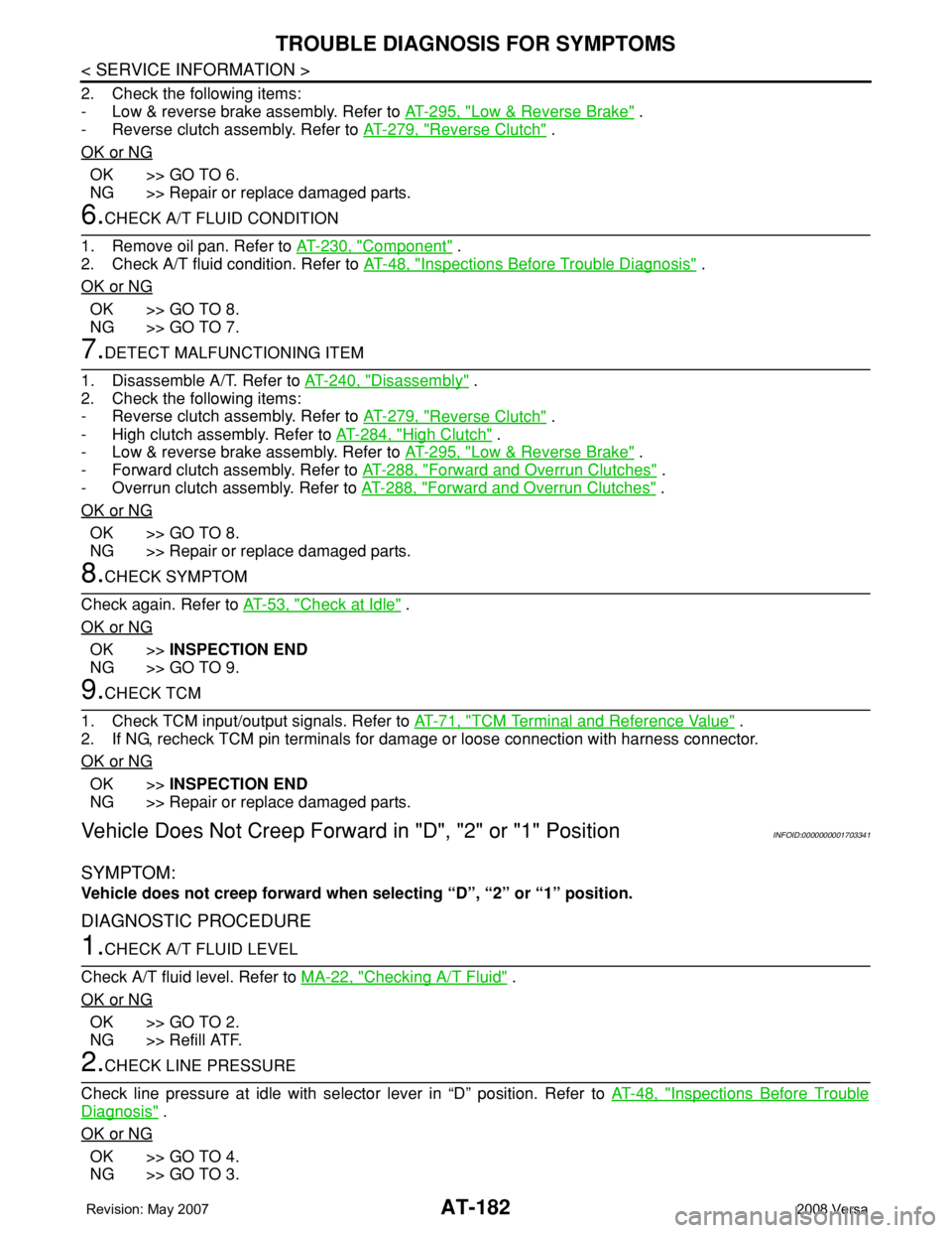
2. Check the following items:
- Low & reverse brake assembly. Refer to AT-295, "
Low & Reverse Brake" .
- Reverse clutch assembly. Refer to AT-279, "
Reverse Clutch" .
OK or NG
OK >> GO TO 6.
NG >> Repair or replace damaged parts.
6.CHECK A/T FLUID CONDITION
1. Remove oil pan. Refer to AT-230, "
Component" .
2. Check A/T fluid condition. Refer to AT-48, "
Inspections Before Trouble Diagnosis" .
OK or NG
OK >> GO TO 8.
NG >> GO TO 7.
7.DETECT MALFUNCTIONING ITEM
1. Disassemble A/T. Refer to AT-240, "
Disassembly" .
2. Check the following items:
- Reverse clutch assembly. Refer to AT-279, "
Reverse Clutch" .
- High clutch assembly. Refer to AT-284, "
High Clutch" .
- Low & reverse brake assembly. Refer to AT-295, "
Low & Reverse Brake" .
- Forward clutch assembly. Refer to AT-288, "
Forward and Overrun Clutches" .
- Overrun clutch assembly. Refer to AT-288, "
Forward and Overrun Clutches" .
OK or NG
OK >> GO TO 8.
NG >> Repair or replace damaged parts.
8.CHECK SYMPTOM
Check again. Refer to AT-53, "
Check at Idle" .
OK or NG
OK >>INSPECTION END
NG >> GO TO 9.
9.CHECK TCM
1. Check TCM input/output signals. Refer to AT-71, "
TCM Terminal and Reference Value" .
2. If NG, recheck TCM pin terminals for damage or loose connection with harness connector.
OK or NG
OK >>INSPECTION END
NG >> Repair or replace damaged parts.
Vehicle Does Not Creep Forward in "D", "2" or "1" PositionINFOID:0000000001703341
SYMPTOM:
Vehicle does not creep forward when selecting “D”, “2” or “1” position.
DIAGNOSTIC PROCEDURE
1.CHECK A/T FLUID LEVEL
Check A/T fluid level. Refer to MA-22, "
Checking A/T Fluid" .
OK or NG
OK >> GO TO 2.
NG >> Refill ATF.
2.CHECK LINE PRESSURE
Check line pressure at idle with selector lever in “D” position. Refer to AT-48, "
Inspections Before Trouble
Diagnosis" .
OK or NG
OK >> GO TO 4.
NG >> GO TO 3.
Page 195 of 2771
TROUBLE DIAGNOSIS FOR SYMPTOMS
AT-183
< SERVICE INFORMATION >
D
E
F
G
H
I
J
K
L
MA
B
AT
N
O
P
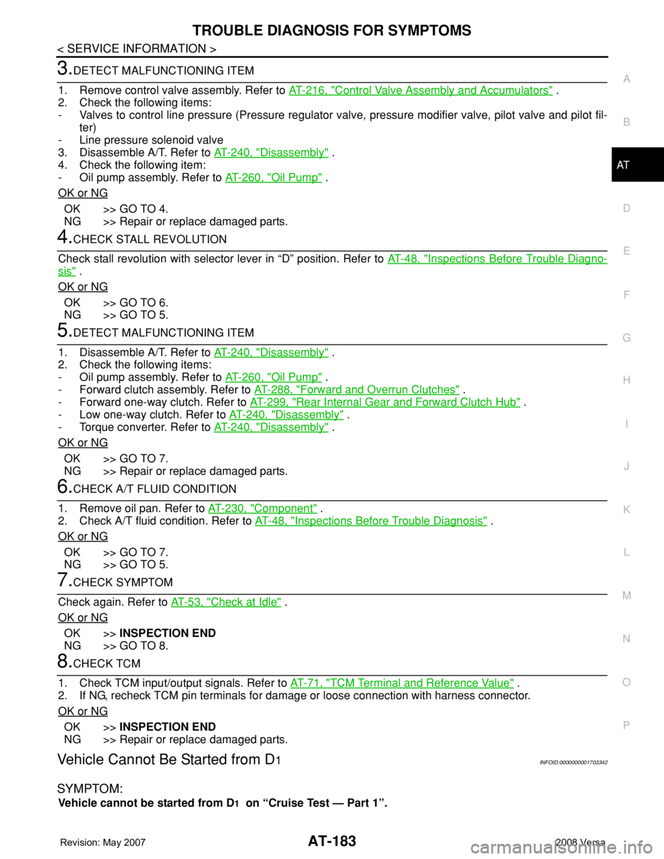
3.DETECT MALFUNCTIONING ITEM
1. Remove control valve assembly. Refer to AT-216, "
Control Valve Assembly and Accumulators" .
2. Check the following items:
- Valves to control line pressure (Pressure regulator valve, pressure modifier valve, pilot valve and pilot fil-
ter)
- Line pressure solenoid valve
3. Disassemble A/T. Refer to AT-240, "
Disassembly" .
4. Check the following item:
- Oil pump assembly. Refer to AT-260, "
Oil Pump" .
OK or NG
OK >> GO TO 4.
NG >> Repair or replace damaged parts.
4.CHECK STALL REVOLUTION
Check stall revolution with selector lever in “D” position. Refer to AT-48, "
Inspections Before Trouble Diagno-
sis" .
OK or NG
OK >> GO TO 6.
NG >> GO TO 5.
5.DETECT MALFUNCTIONING ITEM
1. Disassemble A/T. Refer to AT-240, "
Disassembly" .
2. Check the following items:
- Oil pump assembly. Refer to AT-260, "
Oil Pump" .
- Forward clutch assembly. Refer to AT-288, "
Forward and Overrun Clutches" .
- Forward one-way clutch. Refer to AT-299, "
Rear Internal Gear and Forward Clutch Hub" .
- Low one-way clutch. Refer to AT-240, "
Disassembly" .
- Torque converter. Refer to AT-240, "
Disassembly" .
OK or NG
OK >> GO TO 7.
NG >> Repair or replace damaged parts.
6.CHECK A/T FLUID CONDITION
1. Remove oil pan. Refer to AT-230, "
Component" .
2. Check A/T fluid condition. Refer to AT-48, "
Inspections Before Trouble Diagnosis" .
OK or NG
OK >> GO TO 7.
NG >> GO TO 5.
7.CHECK SYMPTOM
Check again. Refer to AT-53, "
Check at Idle" .
OK or NG
OK >>INSPECTION END
NG >> GO TO 8.
8.CHECK TCM
1. Check TCM input/output signals. Refer to AT-71, "
TCM Terminal and Reference Value" .
2. If NG, recheck TCM pin terminals for damage or loose connection with harness connector.
OK or NG
OK >>INSPECTION END
NG >> Repair or replace damaged parts.
Vehicle Cannot Be Started from D1INFOID:0000000001703342
SYMPTOM:
Vehicle cannot be started from D1 on “Cruise Test — Part 1”.
Page 196 of 2771
AT-184
< SERVICE INFORMATION >
TROUBLE DIAGNOSIS FOR SYMPTOMS
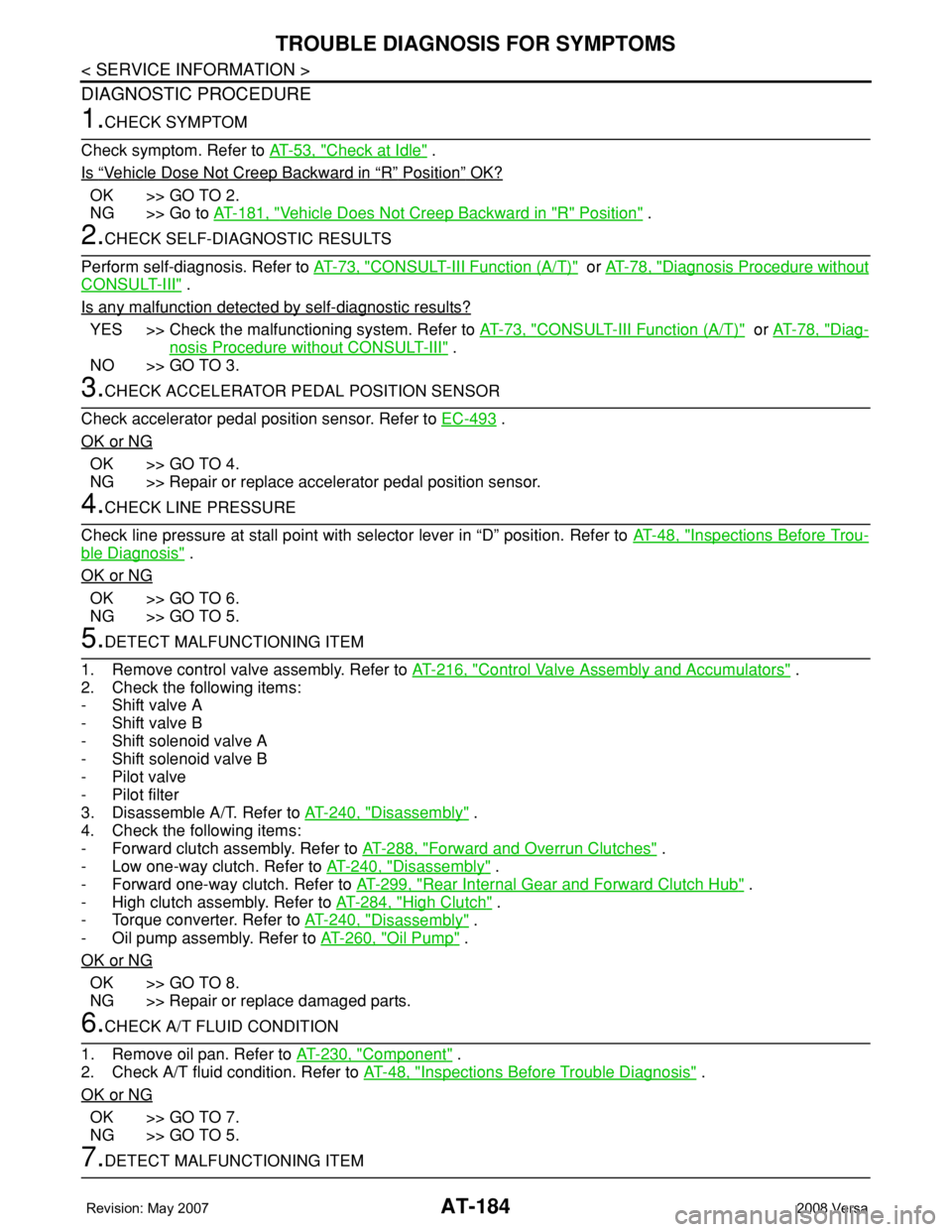
DIAGNOSTIC PROCEDURE
1.CHECK SYMPTOM
Check symptom. Refer to AT-53, "
Check at Idle" .
Is
“Vehicle Dose Not Creep Backward in “R” Position” OK?
OK >> GO TO 2.
NG >> Go to AT-181, "
Vehicle Does Not Creep Backward in "R" Position" .
2.CHECK SELF-DIAGNOSTIC RESULTS
Perform self-diagnosis. Refer to AT-73, "
CONSULT-III Function (A/T)" or AT-78, "Diagnosis Procedure without
CONSULT-III" .
Is any malfunction detected by self-diagnostic results?
YES >> Check the malfunctioning system. Refer to AT-73, "CONSULT-III Function (A/T)" or AT-78, "Diag-
nosis Procedure without CONSULT-III" .
NO >> GO TO 3.
3.CHECK ACCELERATOR PEDAL POSITION SENSOR
Check accelerator pedal position sensor. Refer to EC-493
.
OK or NG
OK >> GO TO 4.
NG >> Repair or replace accelerator pedal position sensor.
4.CHECK LINE PRESSURE
Check line pressure at stall point with selector lever in “D” position. Refer to AT-48, "
Inspections Before Trou-
ble Diagnosis" .
OK or NG
OK >> GO TO 6.
NG >> GO TO 5.
5.DETECT MALFUNCTIONING ITEM
1. Remove control valve assembly. Refer to AT-216, "
Control Valve Assembly and Accumulators" .
2. Check the following items:
- Shift valve A
- Shift valve B
- Shift solenoid valve A
- Shift solenoid valve B
- Pilot valve
- Pilot filter
3. Disassemble A/T. Refer to AT-240, "
Disassembly" .
4. Check the following items:
- Forward clutch assembly. Refer to AT-288, "
Forward and Overrun Clutches" .
- Low one-way clutch. Refer to AT-240, "
Disassembly" .
- Forward one-way clutch. Refer to AT-299, "
Rear Internal Gear and Forward Clutch Hub" .
- High clutch assembly. Refer to AT-284, "
High Clutch" .
- Torque converter. Refer to AT-240, "
Disassembly" .
- Oil pump assembly. Refer to AT-260, "
Oil Pump" .
OK or NG
OK >> GO TO 8.
NG >> Repair or replace damaged parts.
6.CHECK A/T FLUID CONDITION
1. Remove oil pan. Refer to AT-230, "
Component" .
2. Check A/T fluid condition. Refer to AT-48, "
Inspections Before Trouble Diagnosis" .
OK or NG
OK >> GO TO 7.
NG >> GO TO 5.
7.DETECT MALFUNCTIONING ITEM
Page 198 of 2771
AT-186
< SERVICE INFORMATION >
TROUBLE DIAGNOSIS FOR SYMPTOMS
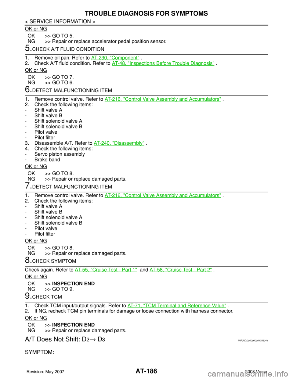
OK or NG
OK >> GO TO 5.
NG >> Repair or replace accelerator pedal position sensor.
5.CHECK A/T FLUID CONDITION
1. Remove oil pan. Refer to AT-230, "
Component" .
2. Check A/T fluid condition. Refer to AT-48, "
Inspections Before Trouble Diagnosis" .
OK or NG
OK >> GO TO 7.
NG >> GO TO 6.
6.DETECT MALFUNCTIONING ITEM
1. Remove control valve. Refer to AT-216, "
Control Valve Assembly and Accumulators" .
2. Check the following items:
- Shift valve A
- Shift valve B
- Shift solenoid valve A
- Shift solenoid valve B
- Pilot valve
- Pilot filter
3. Disassemble A/T. Refer to AT-240, "
Disassembly" .
4. Check the following items:
- Servo piston assembly
- Brake band
OK or NG
OK >> GO TO 8.
NG >> Repair or replace damaged parts.
7.DETECT MALFUNCTIONING ITEM
1. Remove control valve. Refer to AT-216, "
Control Valve Assembly and Accumulators" .
2. Check the following items:
- Shift valve A
- Shift valve B
- Shift solenoid valve A
- Shift solenoid valve B
- Pilot valve
- Pilot filter
OK or NG
OK >> GO TO 8.
NG >> Repair or replace damaged parts.
8.CHECK SYMPTOM
Check again. Refer to AT-55, "
Cruise Test - Part 1" and AT-58, "Cruise Test - Part 2" .
OK or NG
OK >>INSPECTION END
NG >> GO TO 9.
9.CHECK TCM
1. Check TCM input/output signals. Refer to AT-71, "
TCM Terminal and Reference Value" .
2. If NG, recheck TCM pin terminals for damage or loose connection with harness connector.
OK or NG
OK >>INSPECTION END
NG >> Repair or replace damaged parts.
A/T Does Not Shift: D2→ D3INFOID:0000000001703344
SYMPTOM: