2008 NISSAN TIIDA ASSEMBLE
[x] Cancel search: ASSEMBLEPage 10 of 2771
ACCELERATOR CONTROL SYSTEM
ACC-3
< SERVICE INFORMATION >
C
D
E
F
G
H
I
J
K
L
MA
ACC
N
P O
ACCELERATOR CONTROL SYSTEM
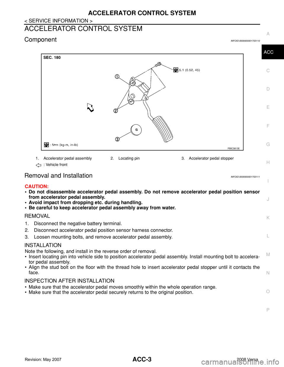
ComponentINFOID:0000000001703110
Removal and InstallationINFOID:0000000001703111
CAUTION:
• Do not disassemble accelerator pedal assembly. Do not remove accelerator pedal position sensor
from accelerator pedal assembly.
• Avoid impact from dropping etc. during handling.
• Be careful to keep accelerator pedal assembly away from water.
REMOVAL
1. Disconnect the negative battery terminal.
2. Disconnect accelerator pedal position sensor harness connector.
3. Loosen mounting bolts, and remove accelerator pedal assembly.
INSTALLATION
Note the following, and install in the reverse order of removal.
• Insert locating pin into vehicle side to position accelerator pedal assembly. Install mounting bolt to accelera-
tor pedal assembly.
• Align the stud bolt on the floor with the thread hole to insert accelerator pedal stopper until it contacts the
face.
INSPECTION AFTER INSTALLATION
• Make sure that the accelerator pedal moves smoothly within the whole operation range.
• Make sure that the accelerator pedal securely returns to the original position.
1. Accelerator pedal assembly 2. Locating pin 3. Accelerator pedal stopper
: Vehicle front
PBIC3813E
Page 20 of 2771
AT-8
< SERVICE INFORMATION >
PRECAUTIONS
• Be sure to turn the ignition switch OFF and disconnect battery negative cable from battery negative
terminal before any repair or inspection work. The open/short circuit of related switches, sensors,
solenoid valves, etc. will cause the MIL to light up.
• Be sure to connect and lock the connectors securely after work. A loose (unlocked) connector will
cause the MIL to light up due to an open circuit. (Be sure the connectors are free from water, grease,
dirt, bent terminals, etc.)
• Be sure to route and secure the harnesses properly after work. Interference of the harness with a
bracket, etc. may cause the MIL to light up due to a short circuit.
• Be sure to erase the unnecessary malfunction information (repairs completed) from the TCM and
ECM before returning the vehicle to the customer.
PrecautionINFOID:0000000001703154
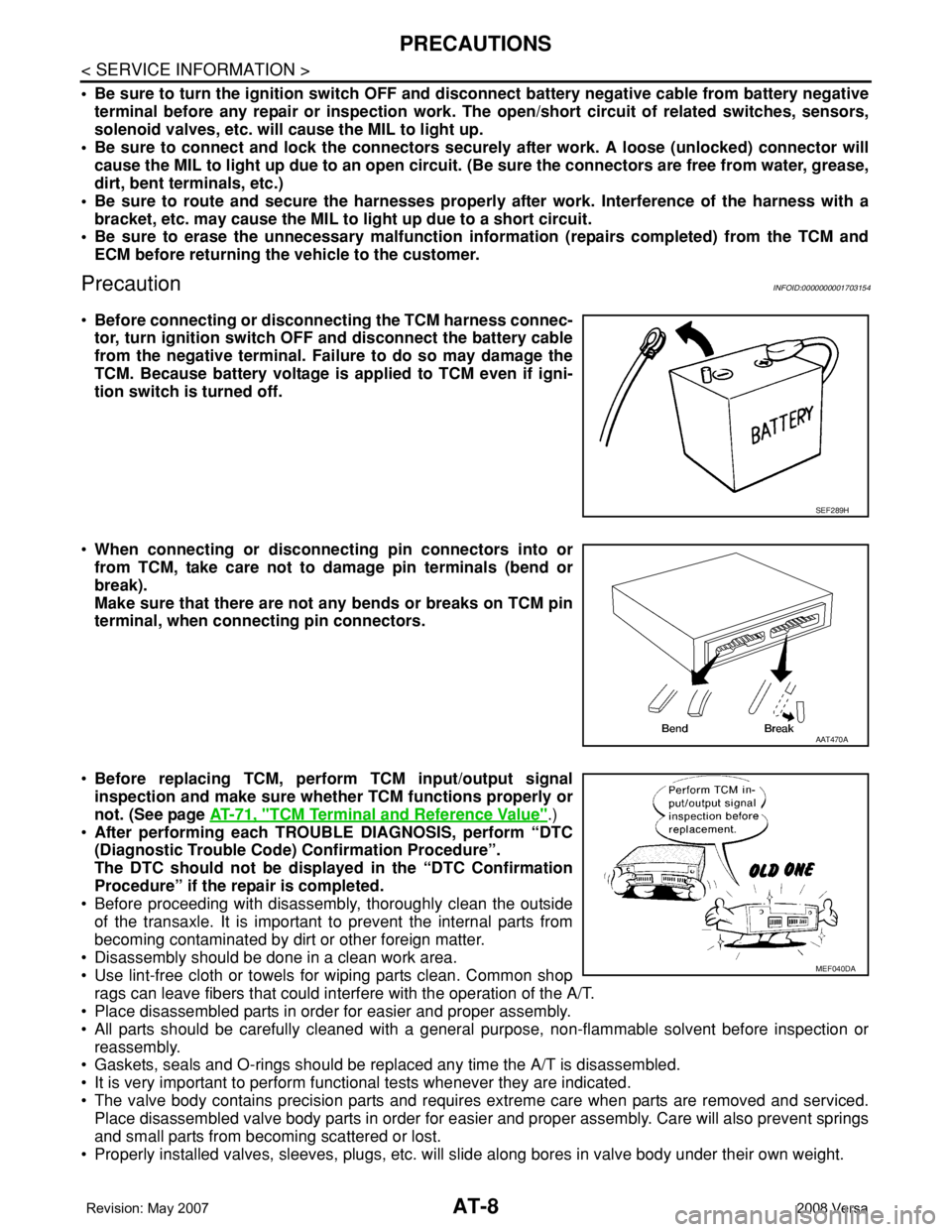
•Before connecting or disconnecting the TCM harness connec-
tor, turn ignition switch OFF and disconnect the battery cable
from the negative terminal. Failure to do so may damage the
TCM. Because battery voltage is applied to TCM even if igni-
tion switch is turned off.
•When connecting or disconnecting pin connectors into or
from TCM, take care not to damage pin terminals (bend or
break).
Make sure that there are not any bends or breaks on TCM pin
terminal, when connecting pin connectors.
•Before replacing TCM, perform TCM input/output signal
inspection and make sure whether TCM functions properly or
not. (See page AT-71, "
TCM Terminal and Reference Value".)
•After performing each TROUBLE DIAGNOSIS, perform “DTC
(Diagnostic Trouble Code) Confirmation Procedure”.
The DTC should not be displayed in the “DTC Confirmation
Procedure” if the repair is completed.
• Before proceeding with disassembly, thoroughly clean the outside
of the transaxle. It is important to prevent the internal parts from
becoming contaminated by dirt or other foreign matter.
• Disassembly should be done in a clean work area.
• Use lint-free cloth or towels for wiping parts clean. Common shop
rags can leave fibers that could interfere with the operation of the A/T.
• Place disassembled parts in order for easier and proper assembly.
• All parts should be carefully cleaned with a general purpose, non-flammable solvent before inspection or
reassembly.
• Gaskets, seals and O-rings should be replaced any time the A/T is disassembled.
• It is very important to perform functional tests whenever they are indicated.
• The valve body contains precision parts and requires extreme care when parts are removed and serviced.
Place disassembled valve body parts in order for easier and proper assembly. Care will also prevent springs
and small parts from becoming scattered or lost.
• Properly installed valves, sleeves, plugs, etc. will slide along bores in valve body under their own weight.
SEF289H
AAT470A
MEF040DA
Page 119 of 2771
DTC P0731 A/T 1ST GEAR FUNCTION
AT-107
< SERVICE INFORMATION >
D
E
F
G
H
I
J
K
L
MA
B
AT
N
O
P
1. Remove control valve assembly. Refer to AT-216, "Control Valve Assembly and Accumulators".
- Shift solenoid valve A
- Shift solenoid valve B
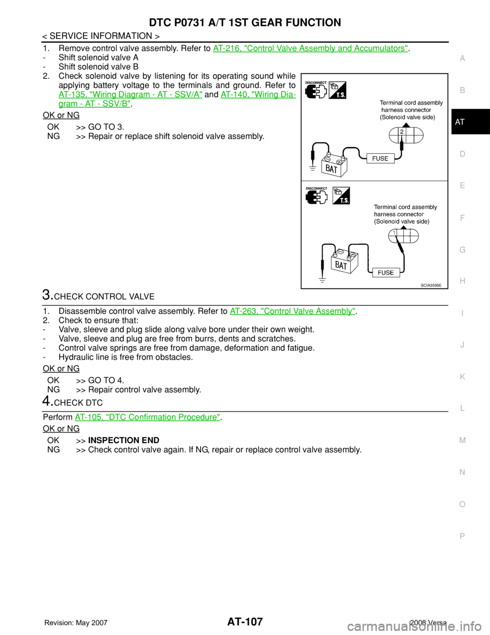
2. Check solenoid valve by listening for its operating sound while
applying battery voltage to the terminals and ground. Refer to
AT-135, "
Wiring Diagram - AT - SSV/A" and AT-140, "Wiring Dia-
gram - AT - SSV/B".
OK or NG
OK >> GO TO 3.
NG >> Repair or replace shift solenoid valve assembly.
3.CHECK CONTROL VALVE
1. Disassemble control valve assembly. Refer to AT-263, "
Control Valve Assembly".
2. Check to ensure that:
- Valve, sleeve and plug slide along valve bore under their own weight.
- Valve, sleeve and plug are free from burrs, dents and scratches.
- Control valve springs are free from damage, deformation and fatigue.
- Hydraulic line is free from obstacles.
OK or NG
OK >> GO TO 4.
NG >> Repair control valve assembly.
4.CHECK DTC
Perform AT-105, "
DTC Confirmation Procedure".
OK or NG
OK >>INSPECTION END
NG >> Check control valve again. If NG, repair or replace control valve assembly.
SCIA3595E
Page 121 of 2771

DTC P0732 A/T 2ND GEAR FUNCTION
AT-109
< SERVICE INFORMATION >
D
E
F
G
H
I
J
K
L
MA
B
AT
N
O
P
-Make sure that “GEAR” shows “3” or “4” after releasing pedal.
6. Depress accelerator pedal to WOT (more than 7.0/8 of “THROTTLE POSI”) quickly from a speed of 45 to
50 km/h (28 to 31 MPH) until “TESTING” changes to “STOP VEHICLE” or “COMPLETE”. (It will take
approximately 3 seconds.)
If the check result NG appears on CONSULT-III screen, go to AT-109, "
Diagnosis Procedure".
If “STOP VEHICLE” appears on CONSULT-III screen, go to following step.
-Make sure that “GEAR” shows “2” when depressing accelerator pedal to WOT.
-If “TESTING” does not appear on CONSULT-III for a long time, select “SELF-DIAG RESULTS” for
“A/T”. In case a DTC other than “P0732 A/T 2ND GR FNCTN” is shown, refer to AT-73, "
CONSULT-
III Function (A/T)".
7. Stop vehicle.
8. Follow the instruction displayed. (Check for normal shifting referring to the table below.)
9. Make sure that “OK” is displayed. (If “NG” is displayed, refer to “Diagnostic Procedure”.)
Refer to AT-109, "
Diagnosis Procedure".
Refer to AT-61, "
Vehicle Speed at Which Gear Shifting Occurs".
WITH GST
Follow the procedure “WITH CONSULT-III”.
Diagnosis ProcedureINFOID:0000000001703240
1.CHECK VALVE RESISTANCE
1. Remove control valve assembly. Refer to AT-216, "
Control Valve Assembly and Accumulators".
- Shift solenoid valve B
2. Check resistance between terminal cord assembly harness con-
nector terminal and ground. Refer to AT-140, "
Wiring Diagram -
AT - SSV/B".
OK or NG
OK >> GO TO 2.
NG >> Repair or replace shift solenoid valve assembly.
2.CHECK VALVE OPERATION
1. Remove control valve assembly. Refer to AT-216, "
Control Valve Assembly and Accumulators".
- Shift solenoid valve B
2. Check solenoid valve by listening for its operating sound while
applying battery voltage to the terminal and ground. Refer to AT-
140, "Wiring Diagram - AT - SSV/B".
OK or NG
OK >> GO TO 3.
NG >> Repair or replace shift solenoid valve assembly.
3.CHECK CONTROL VALVE
1. Disassemble control valve assembly. Refer to AT-263, "
Control Valve Assembly".
2. Check to ensure that:
- Valve, sleeve and plug slide along valve bore under their own weight.
Vehicle condition Gear on actual transmission shift pattern when screen is changed to 1 → 2 → 3 → 4
No malfunction exists 1 → 2 → 3 → 4
Malfunction for “A/T 2ND GR FNCTN” exists. 4 → 3 → 3 → 4
Solenoid valve Connector Terminal Resistance (Approx.)
Shift solenoid valve B F30 1 - Ground 5 - 20 Ω
SCIA3454E
SCIA2058E
Page 125 of 2771
DTC P0733 A/T 3RD GEAR FUNCTION
AT-113
< SERVICE INFORMATION >
D
E
F
G
H
I
J
K
L
MA
B
AT
N
O
P
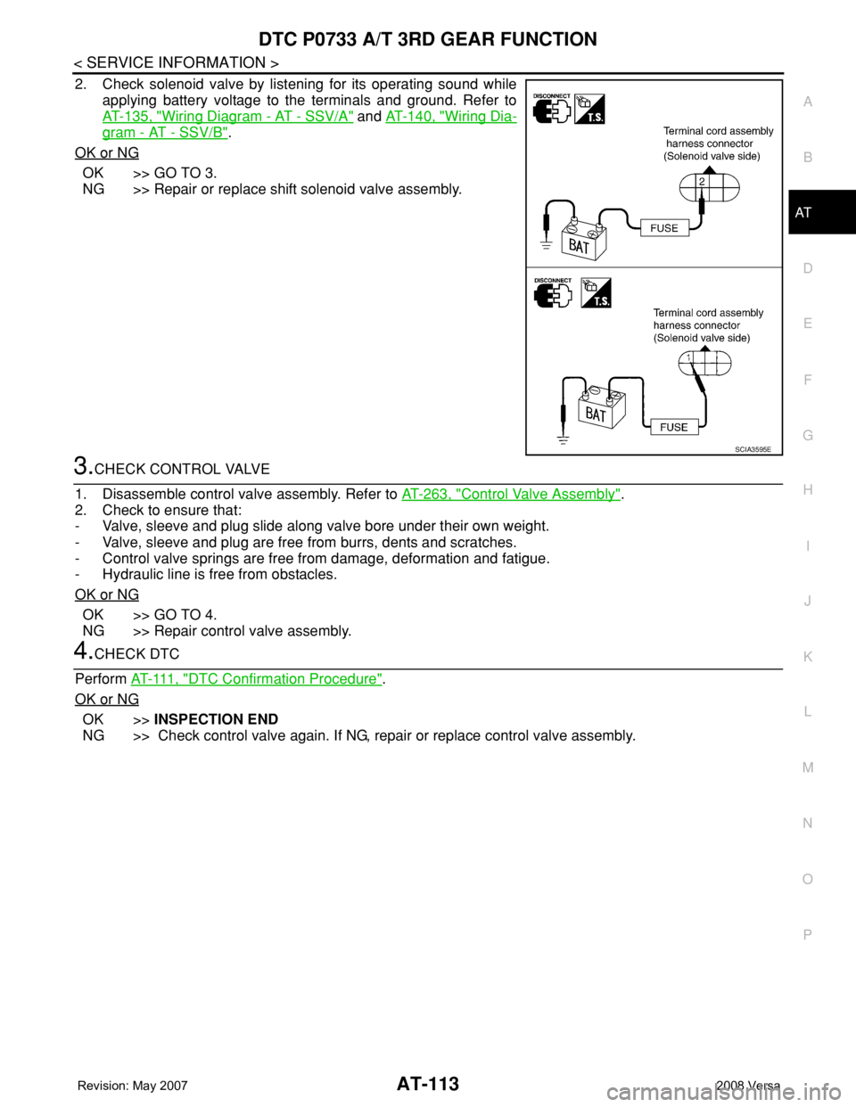
2. Check solenoid valve by listening for its operating sound while
applying battery voltage to the terminals and ground. Refer to
AT-135, "
Wiring Diagram - AT - SSV/A" and AT-140, "Wiring Dia-
gram - AT - SSV/B".
OK or NG
OK >> GO TO 3.
NG >> Repair or replace shift solenoid valve assembly.
3.CHECK CONTROL VALVE
1. Disassemble control valve assembly. Refer to AT-263, "
Control Valve Assembly".
2. Check to ensure that:
- Valve, sleeve and plug slide along valve bore under their own weight.
- Valve, sleeve and plug are free from burrs, dents and scratches.
- Control valve springs are free from damage, deformation and fatigue.
- Hydraulic line is free from obstacles.
OK or NG
OK >> GO TO 4.
NG >> Repair control valve assembly.
4.CHECK DTC
Perform AT- 111 , "
DTC Confirmation Procedure".
OK or NG
OK >>INSPECTION END
NG >> Check control valve again. If NG, repair or replace control valve assembly.
SCIA3595E
Page 128 of 2771
AT-116
< SERVICE INFORMATION >
DTC P0734 A/T 4TH GEAR FUNCTION
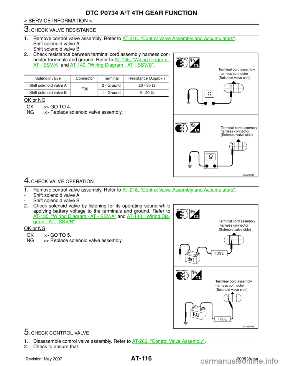
3.CHECK VALVE RESISTANCE
1. Remove control valve assembly. Refer to AT-216, "
Control Valve Assembly and Accumulators".
- Shift solenoid valve A
- Shift solenoid valve B
2. Check resistance between terminal cord assembly harness con-
nector terminals and ground. Refer to AT-135, "
Wiring Diagram -
AT - SSV/A" and AT-140, "Wiring Diagram - AT - SSV/B".
OK or NG
OK >> GO TO 4.
NG >> Replace solenoid valve assembly.
4.CHECK VALVE OPERATION
1. Remove control valve assembly. Refer to AT-216, "
Control Valve Assembly and Accumulators".
- Shift solenoid valve A
- Shift solenoid valve B
2. Check solenoid valve by listening for its operating sound while
applying battery voltage to the terminals and ground. Refer to
AT-135, "
Wiring Diagram - AT - SSV/A" and AT-140, "Wiring Dia-
gram - AT - SSV/B".
OK or NG
OK >> GO TO 5.
NG >> Replace solenoid valve assembly.
5.CHECK CONTROL VALVE
1. Disassemble control valve assembly. Refer to AT-263, "
Control Valve Assembly".
2. Check to ensure that:
Solenoid valve Connector Terminal Resistance (Approx.)
Shift solenoid valve A
F302 - Ground 20 - 30 Ω
Shift solenoid valve B 1 - Ground 5 - 20 Ω
SCIA3594E
SCIA3595E
Page 129 of 2771
DTC P0734 A/T 4TH GEAR FUNCTION
AT-117
< SERVICE INFORMATION >
D
E
F
G
H
I
J
K
L
MA
B
AT
N
O
P
- Valve, sleeve and plug slide along valve bore under their own weight.
- Valve, sleeve and plug are free from burrs, dents and scratches.
- Control valve springs are free from damage, deformation and fatigue.
- Hydraulic line is free from obstacles.
OK or NG
OK >> GO TO 6.
NG >> Repair control valve.
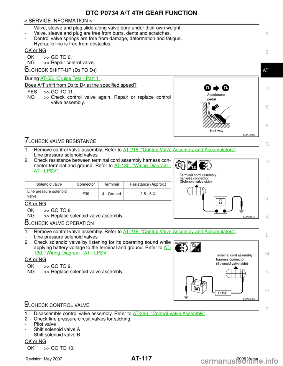
6.CHECK SHIFT-UP (D3 TO D4)
During AT-55, "
Cruise Test - Part 1".
Does A/T shift from D
3 to D4 at the specified speed?
YES >> GO TO 11.
NO >> Check control valve again. Repair or replace control
valve assembly.
7.CHECK VALVE RESISTANCE
1. Remove control valve assembly. Refer to AT-216, "
Control Valve Assembly and Accumulators".
- Line pressure solenoid valves
2. Check resistance between terminal cord assembly harness con-
nector terminal and ground. Refer to AT-130, "
Wiring Diagram -
AT - L P S V".
OK or NG
OK >> GO TO 8.
NG >> Replace solenoid valve assembly.
8.CHECK VALVE OPERATION
1. Remove control valve assembly. Refer to AT-216, "
Control Valve Assembly and Accumulators".
- Line pressure solenoid valves
2. Check solenoid valve by listening for its operating sound while
applying battery voltage to the terminal and ground. Refer to AT-
130, "Wiring Diagram - AT - LPSV".
OK or NG
OK >> GO TO 9.
NG >> Replace solenoid valve assembly.
9.CHECK CONTROL VALVE
1. Disassemble control valve assembly. Refer to AT-263, "
Control Valve Assembly".
2. Check line pressure circuit valves for sticking.
- Pilot valve
- Shift solenoid valve A
- Shift solenoid valve B
OK or NG
OK >> GO TO 10.
SCIA7190E
Solenoid valve Connector Terminal Resistance (Approx.)
Line pressure solenoid
valveF30 4 - Ground 2.5 - 5 Ω
SCIA3457E
SCIA3275E
Page 137 of 2771
DTC P0744 A/T TCC S/V FUNCTION (LOCK-UP)
AT-125
< SERVICE INFORMATION >
D
E
F
G
H
I
J
K
L
MA
B
AT
N
O
P
5. Accelerate vehicle to more than 80 km/h (50 MPH) and maintain the following conditions continuously
until “TESTING” has turned to “COMPLETE”. (It will take approximately 30 seconds after “TESTING”
shows.)
THROTTLE POSI: 1.0/8 - 2.0/8 (at all times during step 4)
SLCT LVR POSI: “D” position
TCC S/V DUTY: More than 94%
VEHICLE SPEED: Constant speed of more than 80 km/h (50 MPH)
-Make sure that “GEAR” shows “4”.
-For shift schedule, refer to AT-61, "
Vehicle Speed at Which Gear Shifting Occurs".
-If “TESTING” does not appear on CONSULT-III for a long time, select “SELF-DIAG RESULTS”. In
case a DTC other than “P0744 A/T TCC S/V FNCTN” is shown, refer to AT-73, "
CONSULT-III Func-
tion (A/T)".
6. Make sure that “OK” is displayed. (If “NG” is displayed, refer to “DIAGNOSTIC PROCEDURE”.)
Refer to AT-125, "
Diagnosis Procedure".
Refer to AT-61, "
Vehicle Speed at Which Lock-up Occurs/Releases".
WITH GST
Follow the procedure “WITH CONSULT-III”.
Diagnosis ProcedureINFOID:0000000001703265
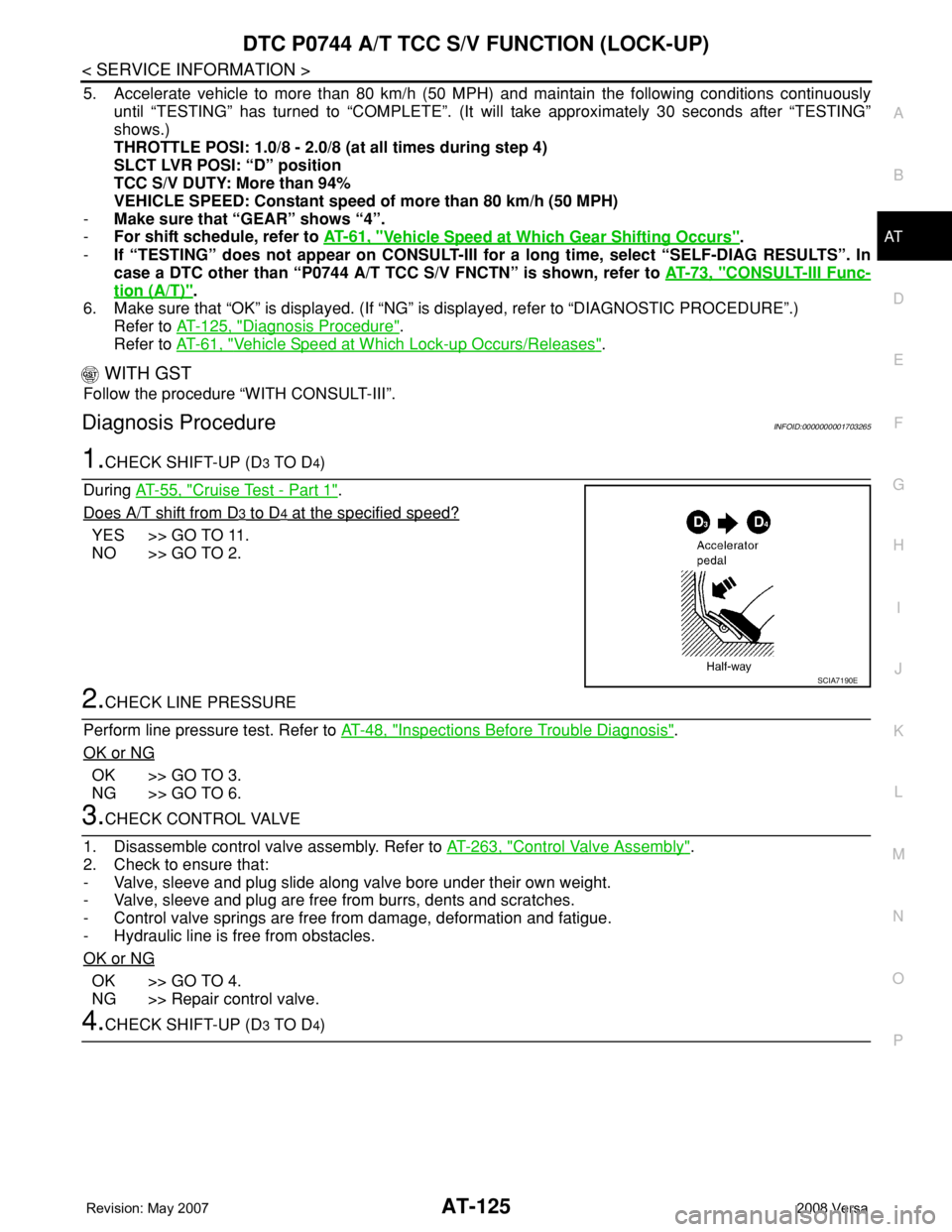
1.CHECK SHIFT-UP (D3 TO D4)
During AT-55, "
Cruise Test - Part 1".
Does A/T shift from D
3 to D4 at the specified speed?
YES >> GO TO 11.
NO >> GO TO 2.
2.CHECK LINE PRESSURE
Perform line pressure test. Refer to AT-48, "
Inspections Before Trouble Diagnosis".
OK or NG
OK >> GO TO 3.
NG >> GO TO 6.
3.CHECK CONTROL VALVE
1. Disassemble control valve assembly. Refer to AT-263, "
Control Valve Assembly".
2. Check to ensure that:
- Valve, sleeve and plug slide along valve bore under their own weight.
- Valve, sleeve and plug are free from burrs, dents and scratches.
- Control valve springs are free from damage, deformation and fatigue.
- Hydraulic line is free from obstacles.
OK or NG
OK >> GO TO 4.
NG >> Repair control valve.
4.CHECK SHIFT-UP (D3 TO D4)
SCIA7190E