2008 NISSAN TIIDA ASSEMBLE
[x] Cancel search: ASSEMBLEPage 229 of 2771
ON-VEHICLE SERVICE
AT-217
< SERVICE INFORMATION >
D
E
F
G
H
I
J
K
L
MA
B
AT
N
O
P
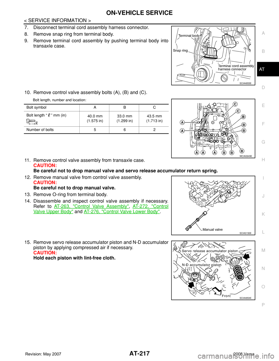
7. Disconnect terminal cord assembly harness connector.
8. Remove snap ring from terminal body.
9. Remove terminal cord assembly by pushing terminal body into
transaxle case.
10. Remove control valve assembly bolts (A), (B) and (C).
Bolt length, number and location:
11. Remove control valve assembly from transaxle case.
CAUTION:
Be careful not to drop manual valve and servo release accumulator return spring.
12. Remove manual valve from control valve assembly.
CAUTION:
Be careful not to drop manual valve.
13. Remove O-ring from terminal body.
14. Disassemble and inspect control valve assembly if necessary.
Refer to AT-263, "
Control Valve Assembly", AT-272, "Control
Valve Upper Body" and AT-276, "Control Valve Lower Body".
15. Remove servo release accumulator piston and N-D accumulator
piston by applying compressed air if necessary.
CAUTION:
Hold each piston with lint-free cloth.
SCIA4853E
Bolt symbol A B C
Bolt length “ ” mm (in)
40.0 mm
(1.575 in)33.0 mm
(1.299 in)43.5 mm
(1.713 in)
Number of bolts 5 6 2
WCIA0649E
SCIA3150E
SCIA4854E
Page 266 of 2771
AT-254
< SERVICE INFORMATION >
DISASSEMBLY
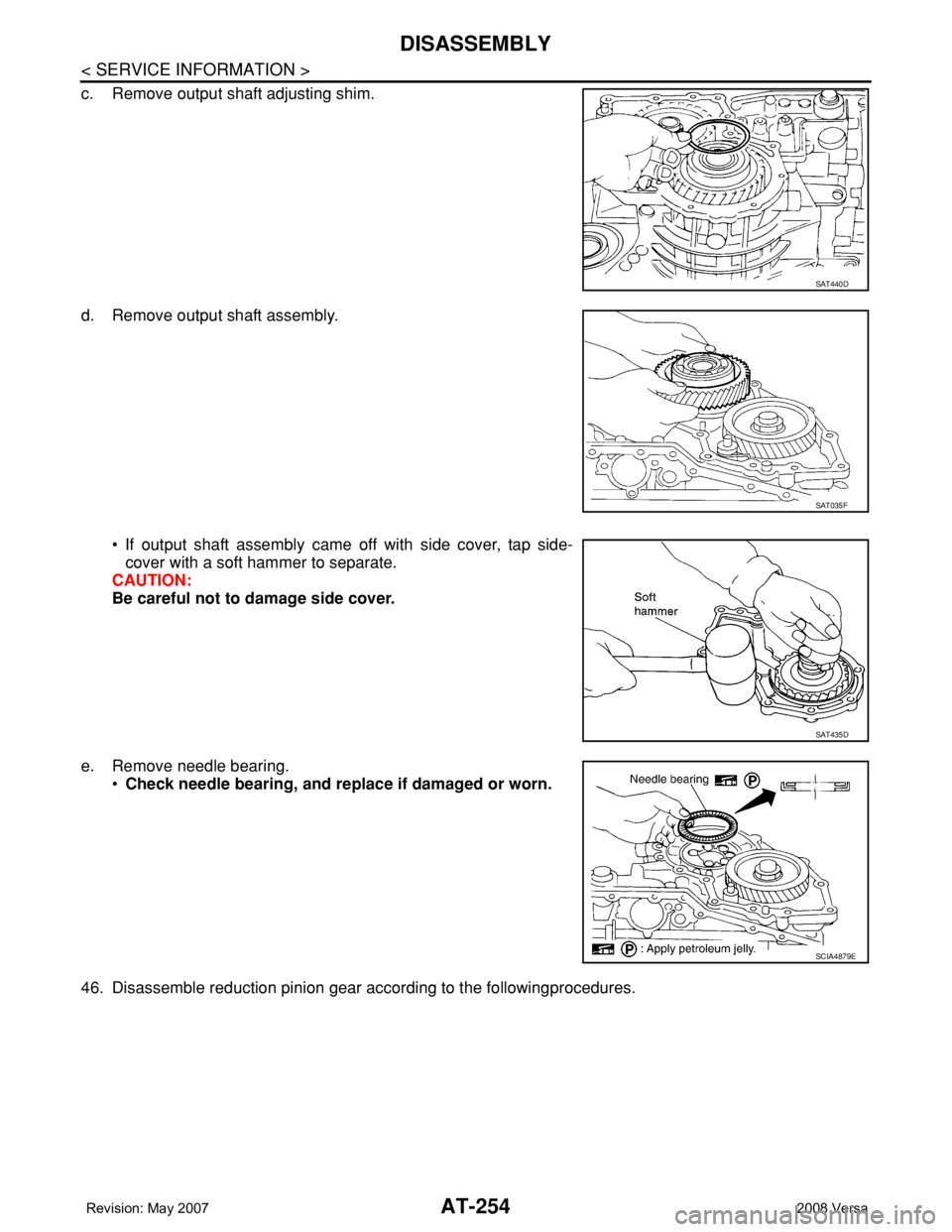
c. Remove output shaft adjusting shim.
d. Remove output shaft assembly.
• If output shaft assembly came off with side cover, tap side-
cover with a soft hammer to separate.
CAUTION:
Be careful not to damage side cover.
e. Remove needle bearing.
•Check needle bearing, and replace if damaged or worn.
46. Disassemble reduction pinion gear according to the followingprocedures.
SAT440D
SAT035F
SAT435D
SCIA4879E
Page 741 of 2771
BR-10
< SERVICE INFORMATION >
BRAKE TUBE AND HOSE
BRAKE TUBE AND HOSE
Hydraulic CircuitINFOID:0000000001703784
CAUTION:
• All tubes and hoses must be free from excessive bending, twisting and pulling.
• Make sure there is no interference with other parts when turning steering both clockwise and coun-
terclockwise.
• Brake tubes and hoses are an important safety part. Always disassemble the parts and retighten
their fittings, if a brake fluid leak is detected. Replace applicable part with a new one, if damaged part
is detected.
• Be careful not to splash brake fluid on painted areas; it way cause paint damage. If brake fluid is
splashed on painted surfaces of body, immediately wipe them with cloth and then wash it away with
water.
• Do not bend or twist brake hose sharply, or strongly pull it.
• When removing components, cover brake line connections so that dirt, dust, or other foreign mat-
ters do not get in.
• Refill using recommended brake fluid. Refer to MA-10
.
• Never reuse drained brake fluid.
Front Brake Tube and HoseINFOID:0000000001703785
REMOVAL
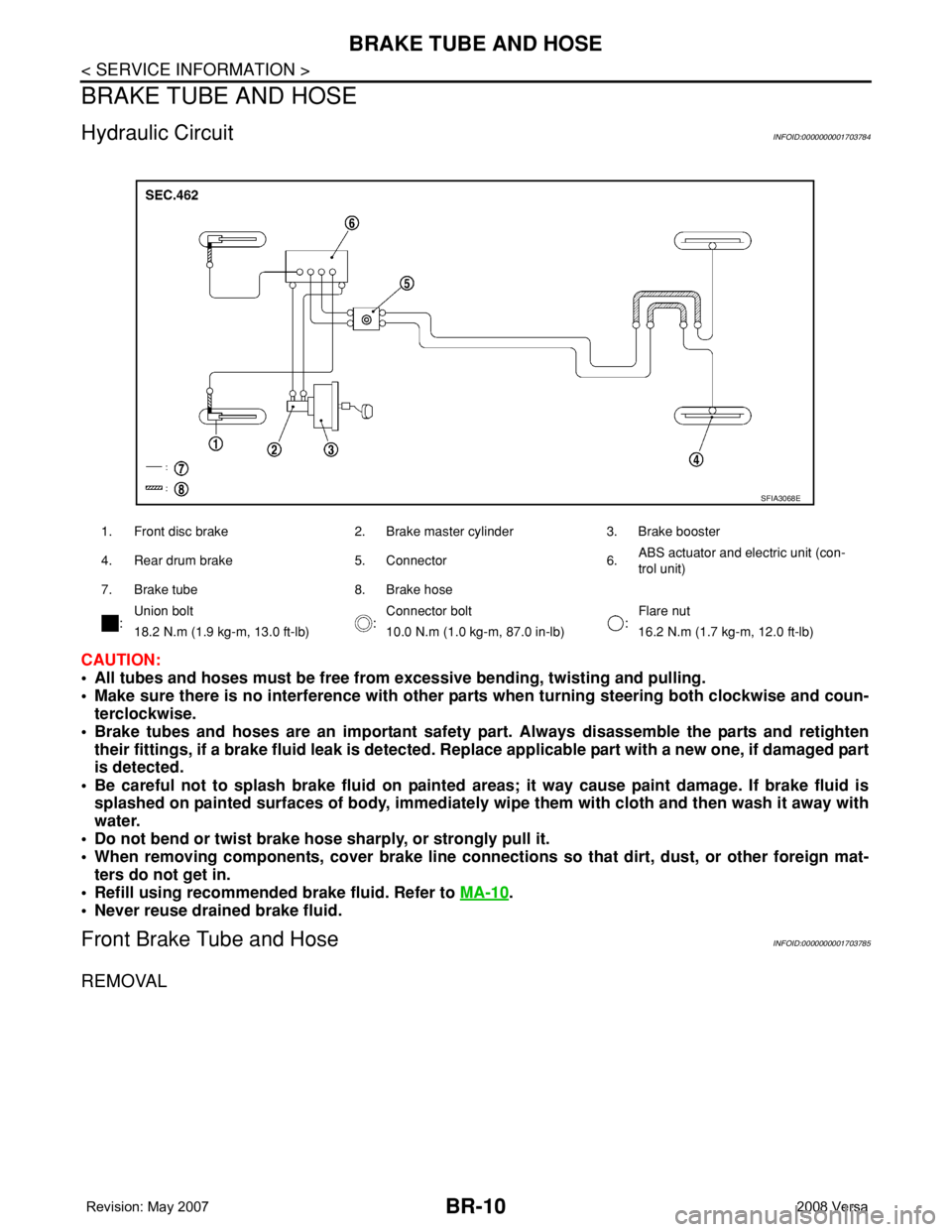
1. Front disc brake 2. Brake master cylinder 3. Brake booster
4. Rear drum brake 5. Connector 6.ABS actuator and electric unit (con-
trol unit)
7. Brake tube 8. Brake hose
:Union bolt
:Connector bolt
:Flare nut
18.2 N.m (1.9 kg-m, 13.0 ft-lb) 10.0 N.m (1.0 kg-m, 87.0 in-lb) 16.2 N.m (1.7 kg-m, 12.0 ft-lb)
SFIA3068E
Page 742 of 2771
BRAKE TUBE AND HOSE
BR-11
< SERVICE INFORMATION >
C
D
E
G
H
I
J
K
L
MA
B
BR
N
O
P
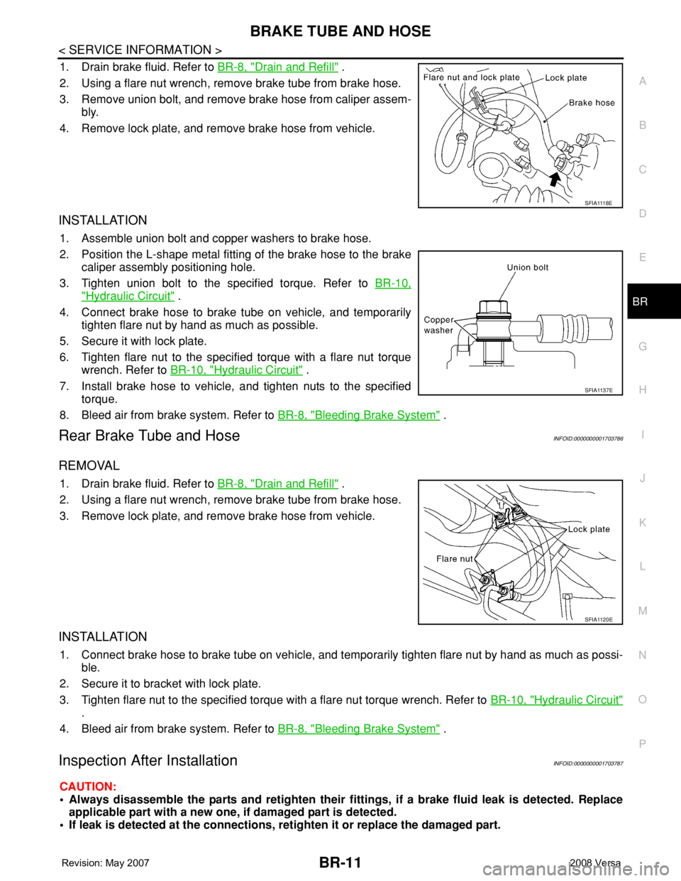
1. Drain brake fluid. Refer to BR-8, "Drain and Refill" .
2. Using a flare nut wrench, remove brake tube from brake hose.
3. Remove union bolt, and remove brake hose from caliper assem-
bly.
4. Remove lock plate, and remove brake hose from vehicle.
INSTALLATION
1. Assemble union bolt and copper washers to brake hose.
2. Position the L-shape metal fitting of the brake hose to the brake
caliper assembly positioning hole.
3. Tighten union bolt to the specified torque. Refer to BR-10,
"Hydraulic Circuit" .
4. Connect brake hose to brake tube on vehicle, and temporarily
tighten flare nut by hand as much as possible.
5. Secure it with lock plate.
6. Tighten flare nut to the specified torque with a flare nut torque
wrench. Refer to BR-10, "
Hydraulic Circuit" .
7. Install brake hose to vehicle, and tighten nuts to the specified
torque.
8. Bleed air from brake system. Refer to BR-8, "
Bleeding Brake System" .
Rear Brake Tube and HoseINFOID:0000000001703786
REMOVAL
1. Drain brake fluid. Refer to BR-8, "Drain and Refill" .
2. Using a flare nut wrench, remove brake tube from brake hose.
3. Remove lock plate, and remove brake hose from vehicle.
INSTALLATION
1. Connect brake hose to brake tube on vehicle, and temporarily tighten flare nut by hand as much as possi-
ble.
2. Secure it to bracket with lock plate.
3. Tighten flare nut to the specified torque with a flare nut torque wrench. Refer to BR-10, "
Hydraulic Circuit"
.
4. Bleed air from brake system. Refer to BR-8, "
Bleeding Brake System" .
Inspection After InstallationINFOID:0000000001703787
CAUTION:
• Always disassemble the parts and retighten their fittings, if a brake fluid leak is detected. Replace
applicable part with a new one, if damaged part is detected.
• If leak is detected at the connections, retighten it or replace the damaged part.
S F I A 111 8 E
SFIA1137E
SFIA1120E
Page 758 of 2771
FRONT DISC BRAKE
BR-27
< SERVICE INFORMATION >
C
D
E
G
H
I
J
K
L
MA
B
BR
N
O
P
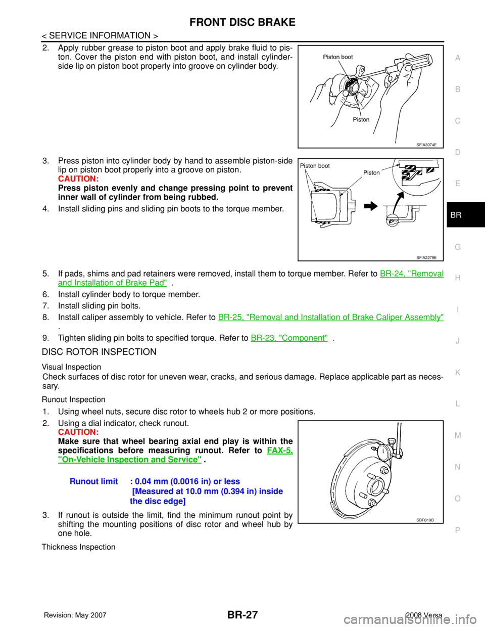
2. Apply rubber grease to piston boot and apply brake fluid to pis-
ton. Cover the piston end with piston boot, and install cylinder-
side lip on piston boot properly into groove on cylinder body.
3. Press piston into cylinder body by hand to assemble piston-side
lip on piston boot properly into a groove on piston.
CAUTION:
Press piston evenly and change pressing point to prevent
inner wall of cylinder from being rubbed.
4. Install sliding pins and sliding pin boots to the torque member.
5. If pads, shims and pad retainers were removed, install them to torque member. Refer to BR-24, "
Removal
and Installation of Brake Pad" .
6. Install cylinder body to torque member.
7. Install sliding pin bolts.
8. Install caliper assembly to vehicle. Refer to BR-25, "
Removal and Installation of Brake Caliper Assembly"
.
9. Tighten sliding pin bolts to specified torque. Refer to BR-23, "
Component" .
DISC ROTOR INSPECTION
Visual Inspection
Check surfaces of disc rotor for uneven wear, cracks, and serious damage. Replace applicable part as neces-
sary.
Runout Inspection
1. Using wheel nuts, secure disc rotor to wheels hub 2 or more positions.
2. Using a dial indicator, check runout.
CAUTION:
Make sure that wheel bearing axial end play is within the
specifications before measuring runout. Refer to FA X - 5 ,
"On-Vehicle Inspection and Service" .
3. If runout is outside the limit, find the minimum runout point by
shifting the mounting positions of disc rotor and wheel hub by
one hole.
Thickness Inspection
SFIA3074E
SFIA2279E
Runout limit : 0.04 mm (0.0016 in) or less
[Measured at 10.0 mm (0.394 in) inside
the disc edge]
SBR019B
Page 761 of 2771
BR-30
< SERVICE INFORMATION >
REAR DRUM BRAKE
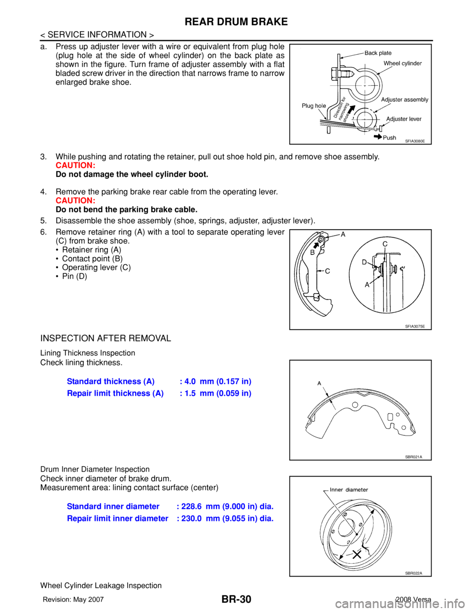
a. Press up adjuster lever with a wire or equivalent from plug hole
(plug hole at the side of wheel cylinder) on the back plate as
shown in the figure. Turn frame of adjuster assembly with a flat
bladed screw driver in the direction that narrows frame to narrow
enlarged brake shoe.
3. While pushing and rotating the retainer, pull out shoe hold pin, and remove shoe assembly.
CAUTION:
Do not damage the wheel cylinder boot.
4. Remove the parking brake rear cable from the operating lever.
CAUTION:
Do not bend the parking brake cable.
5. Disassemble the shoe assembly (shoe, springs, adjuster, adjuster lever).
6. Remove retainer ring (A) with a tool to separate operating lever
(C) from brake shoe.
• Retainer ring (A)
• Contact point (B)
• Operating lever (C)
•Pin (D)
INSPECTION AFTER REMOVAL
Lining Thickness Inspection
Check lining thickness.
Drum Inner Diameter Inspection
Check inner diameter of brake drum.
Measurement area: lining contact surface (center)
Wheel Cylinder Leakage Inspection
SFIA3080E
SFIA3075E
Standard thickness (A) : 4.0 mm (0.157 in)
Repair limit thickness (A) : 1.5 mm (0.059 in)
SBR021A
Standard inner diameter : 228.6 mm (9.000 in) dia.
Repair limit inner diameter : 230.0 mm (9.055 in) dia.
SBR022A
Page 762 of 2771
REAR DRUM BRAKE
BR-31
< SERVICE INFORMATION >
C
D
E
G
H
I
J
K
L
MA
B
BR
N
O
P
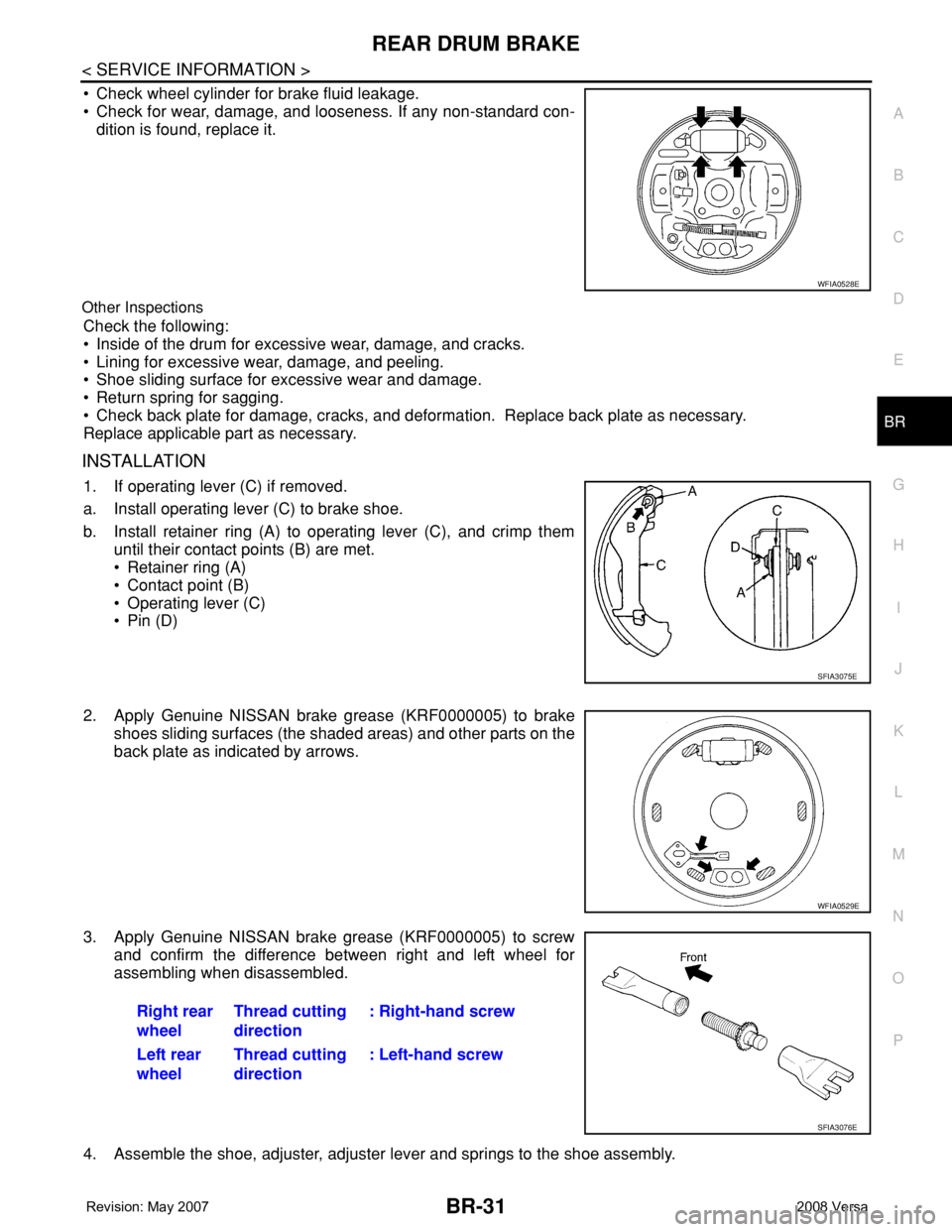
• Check wheel cylinder for brake fluid leakage.
• Check for wear, damage, and looseness. If any non-standard con-
dition is found, replace it.
Other Inspections
Check the following:
• Inside of the drum for excessive wear, damage, and cracks.
• Lining for excessive wear, damage, and peeling.
• Shoe sliding surface for excessive wear and damage.
• Return spring for sagging.
• Check back plate for damage, cracks, and deformation. Replace back plate as necessary.
Replace applicable part as necessary.
INSTALLATION
1. If operating lever (C) if removed.
a. Install operating lever (C) to brake shoe.
b. Install retainer ring (A) to operating lever (C), and crimp them
until their contact points (B) are met.
• Retainer ring (A)
• Contact point (B)
• Operating lever (C)
•Pin (D)
2. Apply Genuine NISSAN brake grease (KRF0000005) to brake
shoes sliding surfaces (the shaded areas) and other parts on the
back plate as indicated by arrows.
3. Apply Genuine NISSAN brake grease (KRF0000005) to screw
and confirm the difference between right and left wheel for
assembling when disassembled.
4. Assemble the shoe, adjuster, adjuster lever and springs to the shoe assembly.
WFIA0528E
SFIA3075E
WFIA0529E
Right rear
wheelThread cutting
direction: Right-hand screw
Left rear
wheelThread cutting
direction: Left-hand screw
SFIA3076E
Page 763 of 2771
BR-32
< SERVICE INFORMATION >
REAR DRUM BRAKE
5. Connect the parking brake rear cable to the operating lever.
6. Install the shoe assembly. After assembly, be sure that each part is installed properly.
CAUTION:
Do not damage the wheel cylinder piston boot.
7. Install the brake drum.
8. Depress brake pedal for several times (approximately 2, 3 times).
9. Adjust clearance of brake shoe. Refer to PB-4, "
On-Vehicle Service" .
10. Install tires to the vehicle.
Removal and Installation of Wheel CylinderINFOID:0000000001703804
REMOVAL
1. Drain brake fluid. Refer to BR-8, "Drain and Refill" .
2. Remove the rear brake shoe assembly. Refer to BR-29, "
Removal and Installation of Drum Brake Assem-
bly" .
3. Remove the brake tube from the wheel cylinder.
4. Remove bolts on the wheel cylinder, and then remove wheel cylinder from the back plate.
INSTALLATION
• Installation is the reverse order of removal. Tighten bolts to the specified torque. Refer to BR-29, "Compo-
nent" .
• Refill with new brake fluid and bleed air. Refer to BR-8, "
Bleeding Brake System" .
Disassembly and Assembly of Wheel CylinderINFOID:0000000001703805
DISASSEMBLY
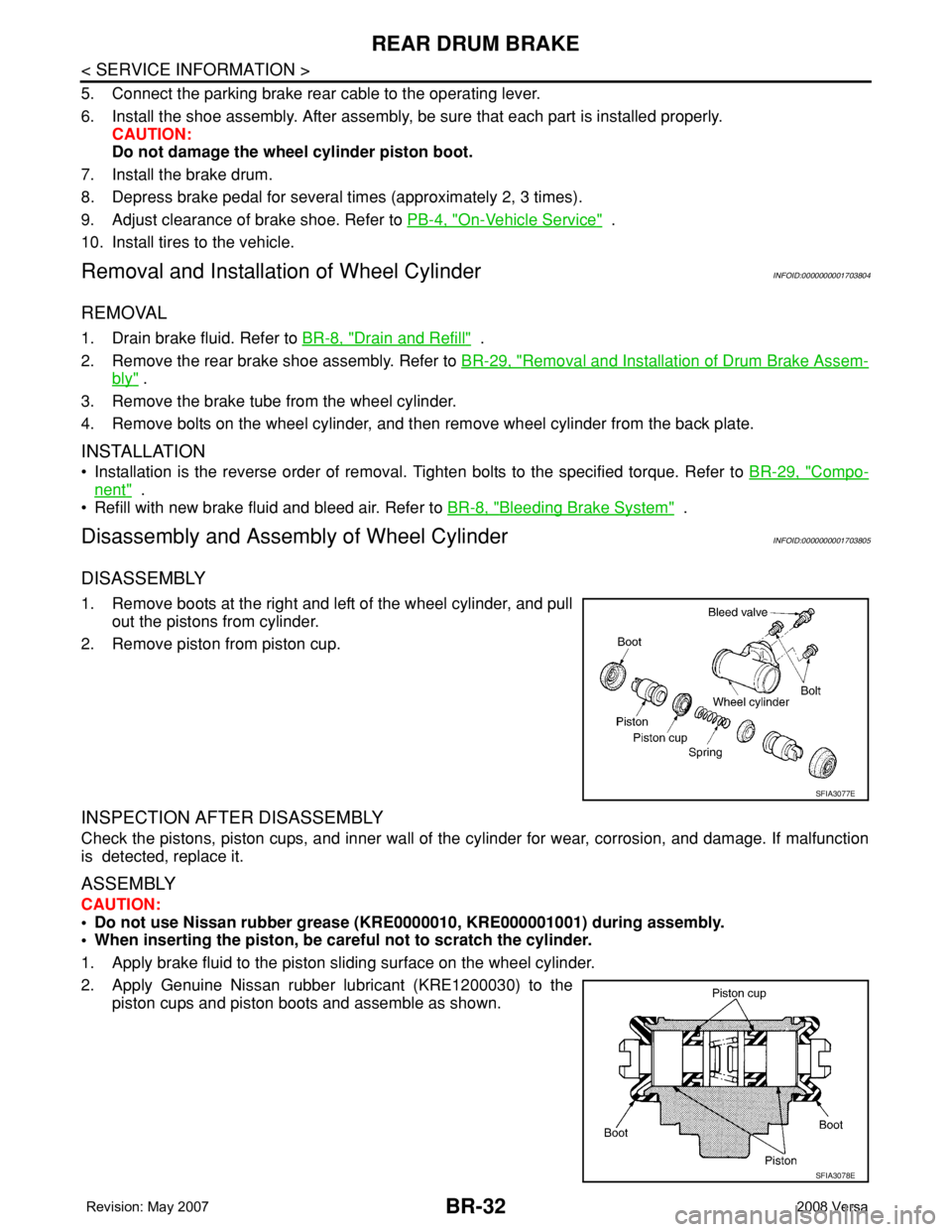
1. Remove boots at the right and left of the wheel cylinder, and pull
out the pistons from cylinder.
2. Remove piston from piston cup.
INSPECTION AFTER DISASSEMBLY
Check the pistons, piston cups, and inner wall of the cylinder for wear, corrosion, and damage. If malfunction
is detected, replace it.
ASSEMBLY
CAUTION:
• Do not use Nissan rubber grease (KRE0000010, KRE000001001) during assembly.
• When inserting the piston, be careful not to scratch the cylinder.
1. Apply brake fluid to the piston sliding surface on the wheel cylinder.
2. Apply Genuine Nissan rubber lubricant (KRE1200030) to the
piston cups and piston boots and assemble as shown.
SFIA3077E
SFIA3078E