2008 NISSAN TIIDA ASSEMBLE
[x] Cancel search: ASSEMBLEPage 767 of 2771
![NISSAN TIIDA 2008 Service Repair Manual BRC-2
< SERVICE INFORMATION >[ABS]
PRECAUTIONS
SERVICE INFORMATION
PRECAUTIONS
Precaution for Supplemental Restraint System (SRS) "AIR BAG" and "SEAT BELT
PRE-TENSIONER"
INFOID:000000](/manual-img/5/57399/w960_57399-766.png "NISSAN TIIDA 2008 Service Repair Manual BRC-2
< SERVICE INFORMATION >[ABS]
PRECAUTIONS
SERVICE INFORMATION
PRECAUTIONS
Precaution for Supplemental Restraint System (SRS) \"AIR BAG\" and \"SEAT BELT
PRE-TENSIONER\"
INFOID:000000")
BRC-2
< SERVICE INFORMATION >[ABS]
PRECAUTIONS
SERVICE INFORMATION
PRECAUTIONS
Precaution for Supplemental Restraint System (SRS) "AIR BAG" and "SEAT BELT
PRE-TENSIONER"
INFOID:0000000001703818
The Supplemental Restraint System such as “AIR BAG” and “SEAT BELT PRE-TENSIONER”, used along
with a front seat belt, helps to reduce the risk or severity of injury to the driver and front passenger for certain
types of collision. This system includes seat belt switch inputs and dual stage front air bag modules. The SRS
system uses the seat belt switches to determine the front air bag deployment, and may only deploy one front
air bag, depending on the severity of a collision and whether the front occupants are belted or unbelted.
Information necessary to service the system safely is included in the SRS and SB section of this Service Man-
ual.
WARNING:
• To avoid rendering the SRS inoperative, which could increase the risk of personal injury or death in
the event of a collision which would result in air bag inflation, all maintenance must be performed by
an authorized NISSAN/INFINITI dealer.
• Improper maintenance, including incorrect removal and installation of the SRS, can lead to personal
injury caused by unintentional activation of the system. For removal of Spiral Cable and Air Bag
Module, see the SRS section.
• Do not use electrical test equipment on any circuit related to the SRS unless instructed to in this
Service Manual. SRS wiring harnesses can be identified by yellow and/or orange harnesses or har-
ness connectors.
Precaution for Brake SystemINFOID:0000000001703819
CAUTION:
• Refer to MA-10
for recommended brake fluid.
• Never reuse drained brake fluid.
• Be careful not to splash brake fluid on painted areas; it may cause paint damage. If brake fluid is
splashed on painted areas, wash it away with water immediately.
• To clean or wash all parts of master cylinder and disc brake caliper, use clean brake fluid.
• Never use mineral oils such as gasoline or kerosene. They will ruin rubber parts of the hydraulic sys-
tem.
• Use flare nut wrench when removing and installing brake
tube.
• If a brake fluid leak is found, the part must be disassembled
without fail. Then it has to be replaced with a new one if a
defect exists.
• Turn the ignition switch OFF and remove the connector of the
ABS actuator and electric unit (control unit) or the battery ter-
minal before performing the work.
• Always torque brake lines when installing.
• Burnish the brake contact surfaces after refinishing or replac-
ing rotors, after replacing pads, or if a soft pedal occurs at
very low mileage. Refer to BR-28, "
Brake Burnishing Proce-
dure".
WARNING:
• Clean brake pads and shoes with a waste cloth, then wipe with a dust collector.
Precaution for Brake ControlINFOID:0000000001703821
• During ABS operation, the brake pedal may vibrate lightly and a mechanical noise may be heard. This is
normal.
• Just after starting the vehicle, the brake pedal may vibrate or motor operating noises may be heard from
engine compartment. This is normal due to the self check operation.
• Stopping distance may be longer than that of vehicles without ABS when vehicle drives on rough, gravel, or
snow-covered (fresh, deep snow) roads.
SBR686C
Page 782 of 2771
![NISSAN TIIDA 2008 Service Repair Manual TROUBLE DIAGNOSIS
BRC-17
< SERVICE INFORMATION >[ABS]
C
D
E
G
H
I
J
K
L
MA
B
BRC
N
O
P
• If ABS actuator and electric unit (control unit) connection is loose, tighten the piping to the specified
tor](/manual-img/5/57399/w960_57399-781.png "NISSAN TIIDA 2008 Service Repair Manual TROUBLE DIAGNOSIS
BRC-17
< SERVICE INFORMATION >[ABS]
C
D
E
G
H
I
J
K
L
MA
B
BRC
N
O
P
• If ABS actuator and electric unit (control unit) connection is loose, tighten the piping to the specified
tor")
TROUBLE DIAGNOSIS
BRC-17
< SERVICE INFORMATION >[ABS]
C
D
E
G
H
I
J
K
L
MA
B
BRC
N
O
P
• If ABS actuator and electric unit (control unit) connection is loose, tighten the piping to the specified
torque and recheck for leaks.
• If there is damage to the connection flare nut or ABS actuator and electric unit (control unit) threads,
replace the damaged part and recheck for leaks.
• When there is fluid leaking or seeping from a fluid connection, use a clean cloth to wipe off the fluid and
recheck for leaks. If fluid is still seeping out, replace the damaged part. If the fluid is leaking at the ABS
actuator and electric unit (control unit), replace the ABS actuator and electric unit (control unit) assem-
bly.
CAUTION:
The ABS actuator and electric unit (control unit) cannot be disassembled and must be replaced
as an assembly.
3. Check the brake pads for excessive wear.
POWER SYSTEM TERMINAL LOOSENESS AND BATTERY INSPECTION
Make sure the battery positive cable, negative cable and ground connection are not loose. In addition, make
sure the battery is sufficiently charged.
ABS WARNING LAMP INSPECTION
1. Make sure ABS warning lamp turns on for approximately 2 seconds when the ignition switch is turned ON.
If it does not, check CAN communications. If there are no errors with the CAN communication system,
replace the combination meter. Refer to IP-11, "
Removal and Installation".
2. Make sure the lamp turns off approximately 2 seconds after the ignition switch is turned ON. If the lamp
does not turn off, conduct self-diagnosis of ABS actuator and electric unit (control unit). If no malfunctions
are detected in self-diagnosis, replace combination meter. Refer to IP-11, "
Removal and Installation".
3. After conducting the self-diagnosis, be sure to erase the error memory. Refer to BRC-18, "
CONSULT-III
Function (ABS)".
Warning Lamp and Indicator TimingINFOID:0000000001703836
Note 1: Brake warning lamp will turn on when the parking brake is applied or when the brake fluid level is low.
x: ON
–: OFF
Control Unit Input/Output Signal StandardINFOID:0000000001703837
REFERENCE VALUE FROM CONSULT-III
CAUTION:
The display shows the control unit calculation data, so a normal value might be displayed even in the
event the output circuit (harness) is open or short circuited.
ConditionABS
warning lampBRAKE
warning lamp
[Note 1]Remarks
When the ignition switch is OFF – – –
After the ignition switch is turned ON for approx. 1
second××–
After the ignition switch is turned ON for approx. 2
seconds––Lamp goes off approx. 2 seconds after the
engine is started.
ABS malfunction×––
EBD malfunction××–
Page 799 of 2771
![NISSAN TIIDA 2008 Service Repair Manual BRC-34
< SERVICE INFORMATION >[ABS]
SENSOR ROTOR
SENSOR ROTOR
Removal and InstallationINFOID:0000000001703851
Sensor rotor cannot be disassembled. To replace sensor rotor, replace hub bearing assembly](/manual-img/5/57399/w960_57399-798.png "NISSAN TIIDA 2008 Service Repair Manual BRC-34
< SERVICE INFORMATION >[ABS]
SENSOR ROTOR
SENSOR ROTOR
Removal and InstallationINFOID:0000000001703851
Sensor rotor cannot be disassembled. To replace sensor rotor, replace hub bearing assembly")
BRC-34
< SERVICE INFORMATION >[ABS]
SENSOR ROTOR
SENSOR ROTOR
Removal and InstallationINFOID:0000000001703851
Sensor rotor cannot be disassembled. To replace sensor rotor, replace hub bearing assembly. Refer to FAX-5
in “FAX” section, refer to RAX-4 in “RAX” section.
Page 803 of 2771
CL-2
< SERVICE INFORMATION >
PRECAUTIONS
SERVICE INFORMATION
PRECAUTIONS
Precaution for Supplemental Restraint System (SRS) "AIR BAG" and "SEAT BELT
PRE-TENSIONER"
INFOID:0000000001703112
The Supplemental Restraint System such as “AIR BAG” and “SEAT BELT PRE-TENSIONER”, used along
with a front seat belt, helps to reduce the risk or severity of injury to the driver and front passenger for certain
types of collision. This system includes seat belt switch inputs and dual stage front air bag modules. The SRS
system uses the seat belt switches to determine the front air bag deployment, and may only deploy one front
air bag, depending on the severity of a collision and whether the front occupants are belted or unbelted.
Information necessary to service the system safely is included in the SRS and SB section of this Service Man-
ual.
WARNING:
• To avoid rendering the SRS inoperative, which could increase the risk of personal injury or death in
the event of a collision which would result in air bag inflation, all maintenance must be performed by
an authorized NISSAN/INFINITI dealer.
• Improper maintenance, including incorrect removal and installation of the SRS, can lead to personal
injury caused by unintentional activation of the system. For removal of Spiral Cable and Air Bag
Module, see the SRS section.
• Do not use electrical test equipment on any circuit related to the SRS unless instructed to in this
Service Manual. SRS wiring harnesses can be identified by yellow and/or orange harnesses or har-
ness connectors.
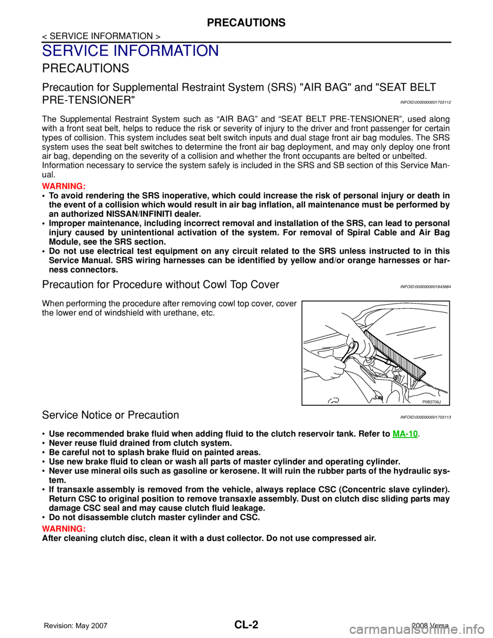
Precaution for Procedure without Cowl Top CoverINFOID:0000000001843684
When performing the procedure after removing cowl top cover, cover
the lower end of windshield with urethane, etc.
Service Notice or PrecautionINFOID:0000000001703113
•Use recommended brake fluid when adding fluid to the clutch reservoir tank. Refer to MA-10.
•Never reuse fluid drained from clutch system.
•Be careful not to splash brake fluid on painted areas.
•Use new brake fluid to clean or wash all parts of master cylinder and operating cylinder.
•Never use mineral oils such as gasoline or kerosene. It will ruin the rubber parts of the hydraulic sys-
tem.
•If transaxle assembly is removed from the vehicle, always replace CSC (Concentric slave cylinder).
Return CSC to original position to remove transaxle assembly. Dust on clutch disc sliding parts may
damage CSC seal and may cause clutch fluid leakage.
•Do not disassemble clutch master cylinder and CSC.
WARNING:
After cleaning clutch disc, clean it with a dust collector. Do not use compressed air.
PIIB3706J
Page 833 of 2771
CO-16
< SERVICE INFORMATION >
WATER PUMP
WATER PUMP
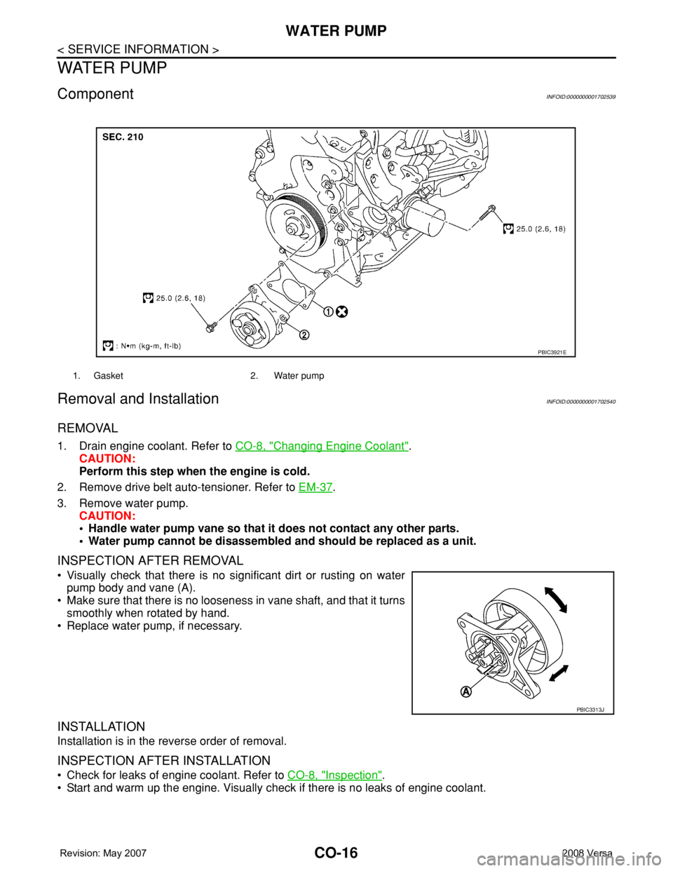
ComponentINFOID:0000000001702539
Removal and InstallationINFOID:0000000001702540
REMOVAL
1. Drain engine coolant. Refer to CO-8, "Changing Engine Coolant".
CAUTION:
Perform this step when the engine is cold.
2. Remove drive belt auto-tensioner. Refer to EM-37
.
3. Remove water pump.
CAUTION:
• Handle water pump vane so that it does not contact any other parts.
• Water pump cannot be disassembled and should be replaced as a unit.
INSPECTION AFTER REMOVAL
• Visually check that there is no significant dirt or rusting on water
pump body and vane (A).
• Make sure that there is no looseness in vane shaft, and that it turns
smoothly when rotated by hand.
• Replace water pump, if necessary.
INSTALLATION
Installation is in the reverse order of removal.
INSPECTION AFTER INSTALLATION
• Check for leaks of engine coolant. Refer to CO-8, "Inspection".
• Start and warm up the engine. Visually check if there is no leaks of engine coolant.
1. Gasket 2. Water pump
PBIC3921E
PBIC3313J
Page 1009 of 2771

CVT-170
< SERVICE INFORMATION >
SHIFT CONTROL SYSTEM
• When installing the control cable (1) to the control device assembly
(2), make sure that the control cable (1) is fully pressed in with the
ribbed surface (A) facing downward from the vehicle.
: Vehicle front
• After installation is completed, adjust and check the CVT position.
Refer to CVT-171, "
Adjustment of CVT Position" and CVT-171,
"Checking of CVT Position".
Control Device Disassembly and AssemblyINFOID:0000000001703680
DISASSEMBLY
NOTE:
Refer to CVT-167, "
Removal and Installation" to disassemble.
1. Remove selector lever knob from control device assembly. Refer to CVT-170, "
Selector Lever Knob
Removal and Installation".
2. Remove position lamp from position indicator plate (1).
3. Insert a flat-bladed screwdriver to (A) (at 4 locations) as shown,
and bend each hook slightly to raise position indicator plate (1)
and remove from control device assembly (2).
4. Remove bracket from control device assembly (2).
5. Remove CVT device harness connector from control device
assembly (2).
6. Release tabs (A) on shift lock solenoid and park position switch
assembly from hooks (B) on control device assembly to shift
lock solenoid and park position switch assembly.
ASSEMBLY
Assembly is in the reverse order of disassembly.
Selector Lever Knob Removal and InstallationINFOID:0000000001703681
REMOVAL
CAUTION:
Make sure that parking brake is applied before removal/installation.
SCIA6253E
SCIA6969E
SCIA6977E
Page 1091 of 2771
PRECAUTIONS
EC-17
< SERVICE INFORMATION >
C
D
E
F
G
H
I
J
K
L
MA
EC
N
P O
PrecautionINFOID:0000000001702551
•Always use a 12 volt battery as power source.
•Do not attempt to disconnect battery cables while engine is
running.
•Before connecting or disconnecting the ECM harness con-
nector, turn ignition switch OFF and disconnect negative bat-
tery cable. Failure to do so may damage the ECM because
battery voltage is applied to ECM even if ignition switch is
turned OFF.
•Before removing parts, turn ignition switch OFF and then dis-
connect negative battery cable.
•Do not disassemble ECM.
•If battery cable is disconnected, the memory will return to the
initial ECM values.
The ECM will now start to self-control at its initial values.
Engine operation can vary slightly when the cable is discon-
nected. However, this is not an indication of a malfunction. Do
not replace parts because of a slight variation.
•If the battery is disconnected, the following emission-related
diagnostic information will be lost within 24 hours.
-Diagnostic trouble codes
-1st trip diagnostic trouble codes
-Freeze frame data
-1st trip freeze frame data
-System readiness test (SRT) codes
-Test values
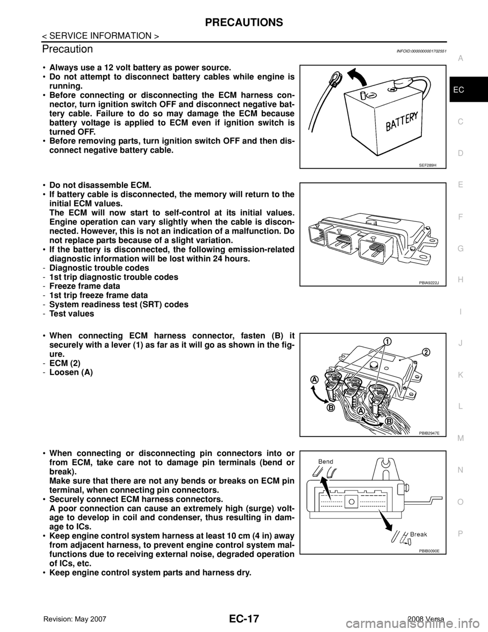
•When connecting ECM harness connector, fasten (B) it
securely with a lever (1) as far as it will go as shown in the fig-
ure.
-ECM (2)
-Loosen (A)
•When connecting or disconnecting pin connectors into or
from ECM, take care not to damage pin terminals (bend or
break).
Make sure that there are not any bends or breaks on ECM pin
terminal, when connecting pin connectors.
•Securely connect ECM harness connectors.
A poor connection can cause an extremely high (surge) volt-
age to develop in coil and condenser, thus resulting in dam-
age to ICs.
•Keep engine control system harness at least 10 cm (4 in) away
from adjacent harness, to prevent engine control system mal-
functions due to receiving external noise, degraded operation
of ICs, etc.
•Keep engine control system parts and harness dry.
SEF289H
PBIA9222J
PBIB2947E
PBIB0090E
Page 1092 of 2771
EC-18
< SERVICE INFORMATION >
PRECAUTIONS
•Before replacing ECM, perform “ECM Terminals and Refer-
ence Value” inspection and make sure ECM functions prop-
erly. Refer to EC-102, "
ECM Terminal and Reference Value".
•Handle mass air flow sensor carefully to avoid damage.
•Do not disassemble mass air flow sensor.
•Do not clean mass air flow sensor with any type of detergent.
•Do not disassemble electric throttle control actuator.
•Even a slight leak in the air intake system can cause serious
incidents.
•Do not shock or jar the camshaft position sensor (PHASE),
crankshaft position sensor (POS).
•After performing each TROUBLE DIAGNOSIS, perform DTC
Confirmation Procedure or Overall Function Check.
The DTC should not be displayed in the DTC Confirmation
Procedure if the repair is completed. The Overall Function
Check should be a good result if the repair is completed.
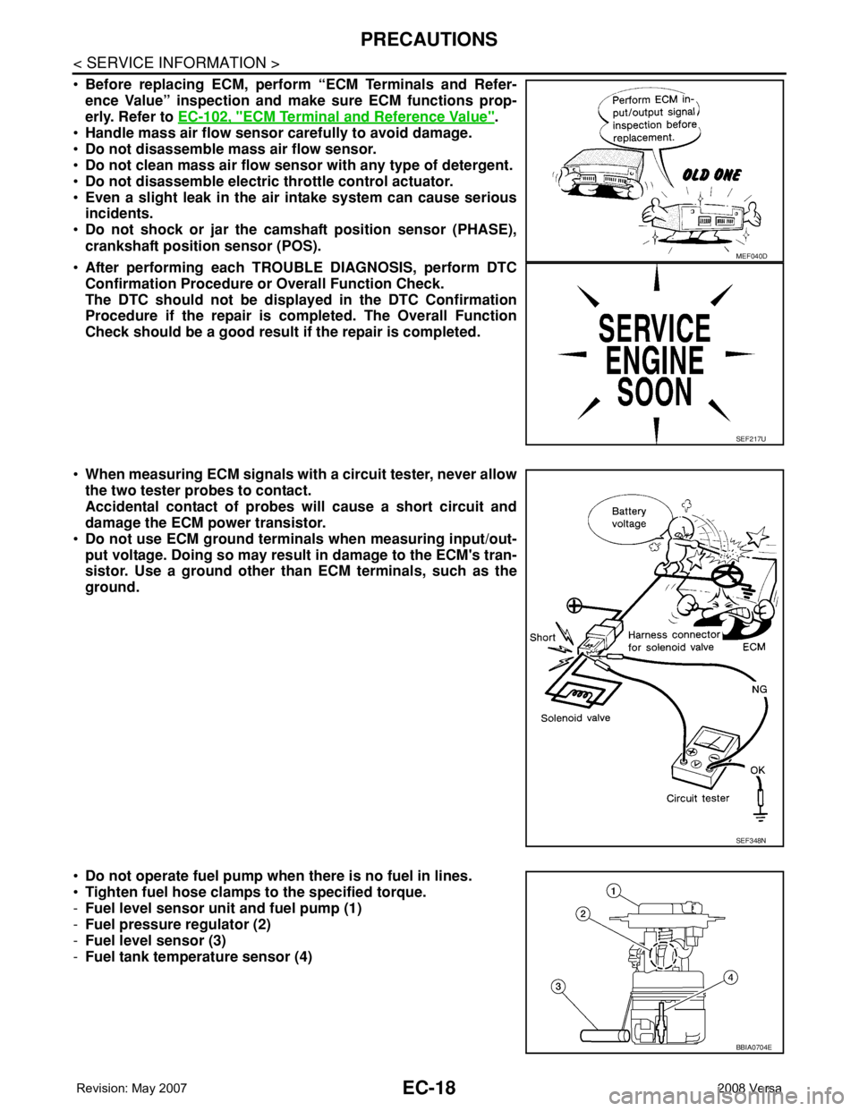
•When measuring ECM signals with a circuit tester, never allow
the two tester probes to contact.
Accidental contact of probes will cause a short circuit and
damage the ECM power transistor.
•Do not use ECM ground terminals when measuring input/out-
put voltage. Doing so may result in damage to the ECM's tran-
sistor. Use a ground other than ECM terminals, such as the
ground.
•Do not operate fuel pump when there is no fuel in lines.
•Tighten fuel hose clamps to the specified torque.
-Fuel level sensor unit and fuel pump (1)
-Fuel pressure regulator (2)
-Fuel level sensor (3)
-Fuel tank temperature sensor (4)
MEF040D
SEF217U
SEF348N
BBIA0704E