2008 NISSAN TIIDA ASSEMBLE
[x] Cancel search: ASSEMBLEPage 2513 of 2771
STEERING WHEEL
PS-7
< SERVICE INFORMATION >
C
D
E
F
H
I
J
K
L
MA
B
PS
N
O
P
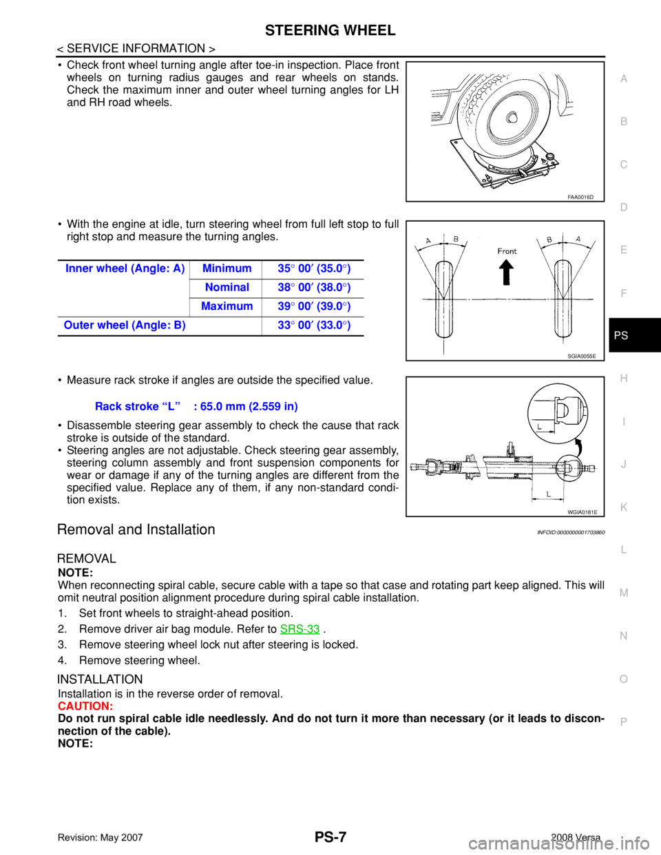
• Check front wheel turning angle after toe-in inspection. Place front
wheels on turning radius gauges and rear wheels on stands.
Check the maximum inner and outer wheel turning angles for LH
and RH road wheels.
• With the engine at idle, turn steering wheel from full left stop to full
right stop and measure the turning angles.
• Measure rack stroke if angles are outside the specified value.
• Disassemble steering gear assembly to check the cause that rack
stroke is outside of the standard.
• Steering angles are not adjustable. Check steering gear assembly,
steering column assembly and front suspension components for
wear or damage if any of the turning angles are different from the
specified value. Replace any of them, if any non-standard condi-
tion exists.
Removal and InstallationINFOID:0000000001703860
REMOVAL
NOTE:
When reconnecting spiral cable, secure cable with a tape so that case and rotating part keep aligned. This will
omit neutral position alignment procedure during spiral cable installation.
1. Set front wheels to straight-ahead position.
2. Remove driver air bag module. Refer to SRS-33
.
3. Remove steering wheel lock nut after steering is locked.
4. Remove steering wheel.
INSTALLATION
Installation is in the reverse order of removal.
CAUTION:
Do not run spiral cable idle needlessly. And do not turn it more than necessary (or it leads to discon-
nection of the cable).
NOTE:
FAA0016D
Inner wheel (Angle: A) Minimum 35° 00′ (35.0°)
Nominal 38° 00′ (38.0°)
Maximum 39° 00′ (39.0°)
Outer wheel (Angle: B) 33° 00′ (33.0°)
SGIA0055E
Rack stroke “L” : 65.0 mm (2.559 in)
WGIA0181E
Page 2515 of 2771
STEERING COLUMN
PS-9
< SERVICE INFORMATION >
C
D
E
F
H
I
J
K
L
MA
B
PS
N
O
P
STEERING COLUMN
Removal and InstallationINFOID:0000000001703861
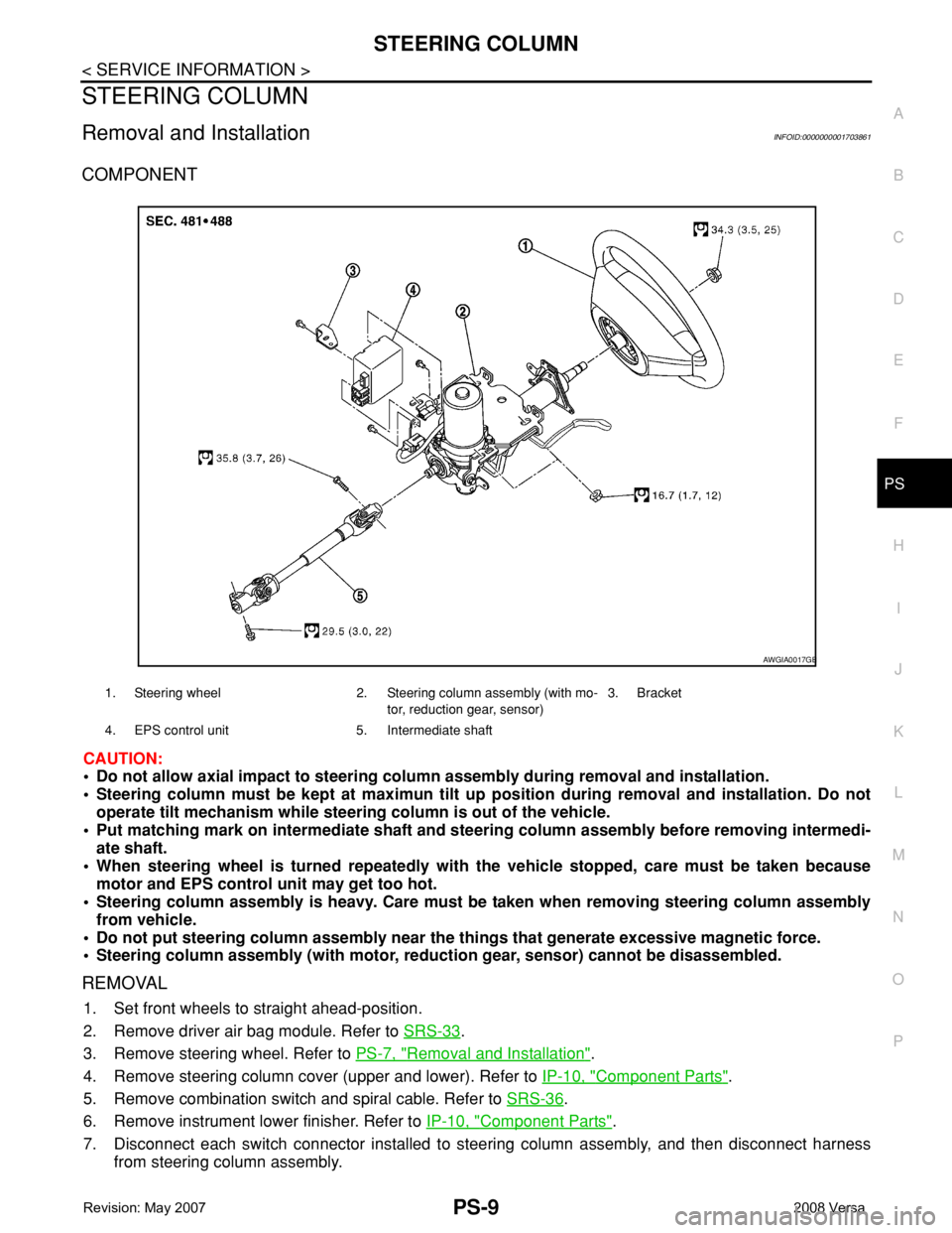
COMPONENT
CAUTION:
• Do not allow axial impact to steering column assembly during removal and installation.
• Steering column must be kept at maximun tilt up position during removal and installation. Do not
operate tilt mechanism while steering column is out of the vehicle.
• Put matching mark on intermediate shaft and steering column assembly before removing intermedi-
ate shaft.
• When steering wheel is turned repeatedly with the vehicle stopped, care must be taken because
motor and EPS control unit may get too hot.
• Steering column assembly is heavy. Care must be taken when removing steering column assembly
from vehicle.
• Do not put steering column assembly near the things that generate excessive magnetic force.
• Steering column assembly (with motor, reduction gear, sensor) cannot be disassembled.
REMOVAL
1. Set front wheels to straight ahead-position.
2. Remove driver air bag module. Refer to SRS-33
.
3. Remove steering wheel. Refer to PS-7, "
Removal and Installation".
4. Remove steering column cover (upper and lower). Refer to IP-10, "
Component Parts".
5. Remove combination switch and spiral cable. Refer to SRS-36
.
6. Remove instrument lower finisher. Refer to IP-10, "
Component Parts".
7. Disconnect each switch connector installed to steering column assembly, and then disconnect harness
from steering column assembly.
1. Steering wheel 2. Steering column assembly (with mo-
tor, reduction gear, sensor)3. Bracket
4. EPS control unit 5. Intermediate shaft
AWGIA0017GB
Page 2573 of 2771
SB-2
< PRECAUTION >
PRECAUTIONS
PRECAUTION
PRECAUTIONS
Precaution for Supplemental Restraint System (SRS) "AIR BAG" and "SEAT BELT
PRE-TENSIONER"
INFOID:0000000001703897
The Supplemental Restraint System such as “AIR BAG” and “SEAT BELT PRE-TENSIONER”, used along
with a front seat belt, helps to reduce the risk or severity of injury to the driver and front passenger for certain
types of collision. This system includes seat belt switch inputs and dual stage front air bag modules. The SRS
system uses the seat belt switches to determine the front air bag deployment, and may only deploy one front
air bag, depending on the severity of a collision and whether the front occupants are belted or unbelted.Infor-
mation necessary to service the system safely is included in the SR and SB section of this Service Manual.
WARNING:
• To avoid rendering the SRS inoperative, which could increase the risk of personal injury or death in
the event of a collision which would result in air bag inflation, all maintenance must be performed by
an authorized NISSAN/INFINITI dealer.
• Improper maintenance, including incorrect removal and installation of the SRS, can lead to personal
injury caused by unintentional activation of the system. For removal of Spiral Cable and Air Bag
Module, see the SRS section.
• Do not use electrical test equipment on any circuit related to the SRS unless instructed to in this
Service Manual. SRS wiring harnesses can be identified by yellow and/or orange harnesses or har-
ness connectors.
Precaution for Seat Belt ServiceINFOID:0000000001703898
CAUTION:
• Before removing the front seat belt pre-tensioner assembly, turn the ignition switch off, disconnect
the both battery cables and wait at least 3 minutes.
• After replacing or reinstalling front seat belt pre-tensioner assembly, or reconnecting front seat belt
pre-tensioner connector, check the system function. Refer to SRS-18, "
SRS Operation Check".
• Do not disassemble buckle or seat belt assembly.
• Do not reuse seat belt anchor bolts after removal. Replace with new ones.
• Replace anchor bolts if they are deformed or worn out.
• Never oil tongue and buckle.
• If any component of seat belt assembly is questionable, do not repair. Replace the whole seat belt
assembly.
• If webbing is cut, frayed, or damaged, replace seat belt assembly.
• When replacing seat belt assembly, use a genuine NISSAN seat belt assembly.
AFTER A COLLISION
WARNING:
• Inspect all seat belt assemblies including retractors and attaching hardware after any collision.
• NISSAN recommends that all seat belt assemblies in use during a collision be replaced unless the
collision was minor and the belts show no damage and continue to operate properly. Failure to do so
could result in serious personal injury in an accident. Seat belt assemblies not in use during a colli-
sion should also be replaced if either damage or improper operation is noted. Seat belt pre-tensioner
should be replaced even if the seat belts are not in use during a frontal collision in which the air bags
are deployed.
Replace any seat belt assembly (including anchor bolts) if:
• The seat belt was in use at the time of a collision (except for minor collisions and the belts, retractors and
buckles show no damage and continue to operate properly).
• The seat belt was damaged in an accident. (i.e. torn webbing, bent retractor or guide).
• The seat belt attaching point was damaged in an accident. Inspect the seat belt attaching area for damage
or distortion and repair as necessary before installing a new seat belt assembly.
• Anchor bolts are deformed or worn out.
• The seat belt pre-tensioner should be replaced even if the seat belts are not in use during the collision in
which the air bags are deployed.
Page 2578 of 2771
SEAT BELTS
SB-7
< ON-VEHICLE REPAIR >
C
D
E
F
G
I
J
K
L
MA
B
SB
N
O
P
5. Remove the outer retractor anchor bolt, then remove outer seat belt retractor.
INSTALLATION OF OUTER SEAT BELT RETRACTOR - HATCHBACK
Installation is in the reverse order of removal.
REMOVAL OF OUTER SEAT BELT RETRACTOR - SEDAN
1. Remove rear seat cushion, refer to SE-14.
2. Remove outer seat belt anchor bolt.
3. Release the seat belt escutcheon, then remove from belt.
4. Remove rear parcel shelf finisher, refer to XXX.
5. Remove outer seat belt retractor bolt, then remove outer seat belt retractor.
INSTALLATION OF OUTER SEAT BELT RETRACTOR - SEDAN
Installation is in the reverse order of removal.
REMOVAL OF CENTER SEAT BELT RETRACTOR - HATCHBACK
1. Remove and disassemble the rear seat cushion, refer to SE-14.
2. Remove the center seat belt retractor.
INSTALLATION OF CENTER SEAT BELT RETRACTOR - HATCHBACK
Installation is in the reverse order of removal.
REMOVAL OF CENTER SEAT BELT RETRACTOR - SEDAN
1. Lift front edge of rear seat cushion and slide forward.
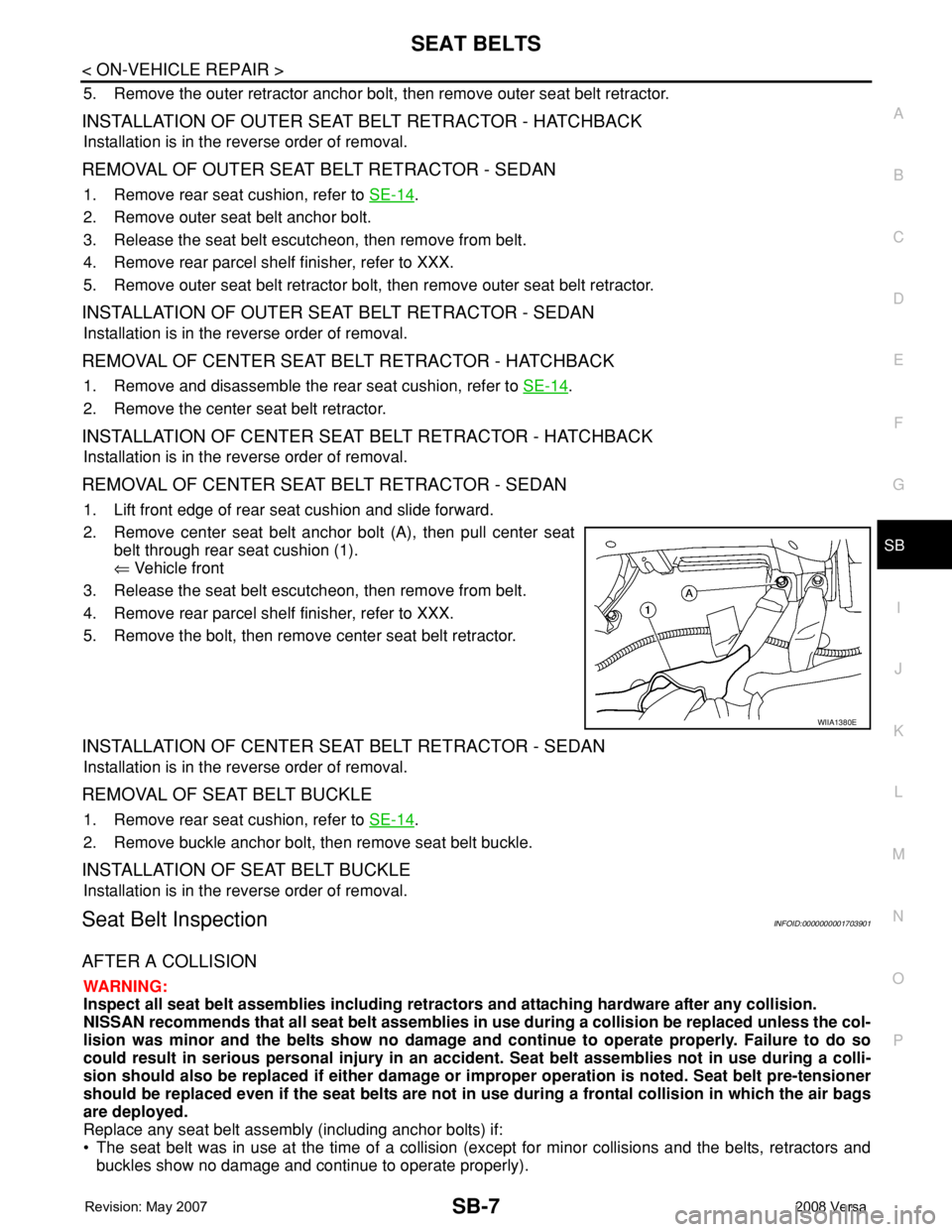
2. Remove center seat belt anchor bolt (A), then pull center seat
belt through rear seat cushion (1).
⇐ Vehicle front
3. Release the seat belt escutcheon, then remove from belt.
4. Remove rear parcel shelf finisher, refer to XXX.
5. Remove the bolt, then remove center seat belt retractor.
INSTALLATION OF CENTER SEAT BELT RETRACTOR - SEDAN
Installation is in the reverse order of removal.
REMOVAL OF SEAT BELT BUCKLE
1. Remove rear seat cushion, refer to SE-14.
2. Remove buckle anchor bolt, then remove seat belt buckle.
INSTALLATION OF SEAT BELT BUCKLE
Installation is in the reverse order of removal.
Seat Belt InspectionINFOID:0000000001703901
AFTER A COLLISION
WARNING:
Inspect all seat belt assemblies including retractors and attaching hardware after any collision.
NISSAN recommends that all seat belt assemblies in use during a collision be replaced unless the col-
lision was minor and the belts show no damage and continue to operate properly. Failure to do so
could result in serious personal injury in an accident. Seat belt assemblies not in use during a colli-
sion should also be replaced if either damage or improper operation is noted. Seat belt pre-tensioner
should be replaced even if the seat belts are not in use during a frontal collision in which the air bags
are deployed.
Replace any seat belt assembly (including anchor bolts) if:
• The seat belt was in use at the time of a collision (except for minor collisions and the belts, retractors and
buckles show no damage and continue to operate properly).
WIIA1380E
Page 2620 of 2771
SE-12
< SERVICE INFORMATION >
FRONT SEAT
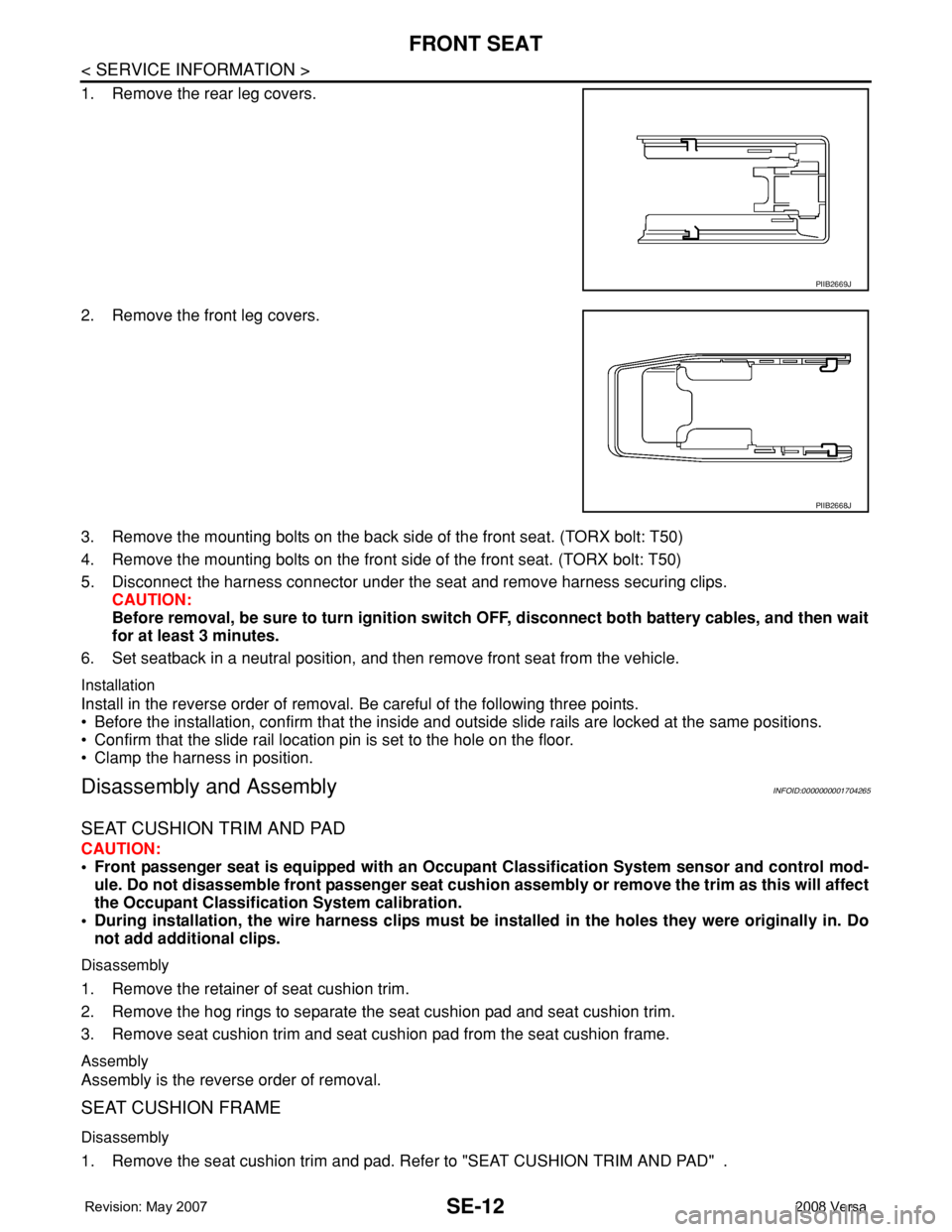
1. Remove the rear leg covers.
2. Remove the front leg covers.
3. Remove the mounting bolts on the back side of the front seat. (TORX bolt: T50)
4. Remove the mounting bolts on the front side of the front seat. (TORX bolt: T50)
5. Disconnect the harness connector under the seat and remove harness securing clips.
CAUTION:
Before removal, be sure to turn ignition switch OFF, disconnect both battery cables, and then wait
for at least 3 minutes.
6. Set seatback in a neutral position, and then remove front seat from the vehicle.
Installation
Install in the reverse order of removal. Be careful of the following three points.
• Before the installation, confirm that the inside and outside slide rails are locked at the same positions.
• Confirm that the slide rail location pin is set to the hole on the floor.
• Clamp the harness in position.
Disassembly and AssemblyINFOID:0000000001704265
SEAT CUSHION TRIM AND PAD
CAUTION:
• Front passenger seat is equipped with an Occupant Classification System sensor and control mod-
ule. Do not disassemble front passenger seat cushion assembly or remove the trim as this will affect
the Occupant Classification System calibration.
• During installation, the wire harness clips must be installed in the holes they were originally in. Do
not add additional clips.
Disassembly
1. Remove the retainer of seat cushion trim.
2. Remove the hog rings to separate the seat cushion pad and seat cushion trim.
3. Remove seat cushion trim and seat cushion pad from the seat cushion frame.
Assembly
Assembly is the reverse order of removal.
SEAT CUSHION FRAME
Disassembly
1. Remove the seat cushion trim and pad. Refer to "SEAT CUSHION TRIM AND PAD" .
PIIB2669J
PIIB2668J
Page 2667 of 2771
DRIVER AIR BAG MODULE
SRS-33
< ON-VEHICLE REPAIR >
C
D
E
F
G
I
J
K
L
MA
B
SRS
N
O
P
ON-VEHICLE REPAIR
DRIVER AIR BAG MODULE
Removal and InstallationINFOID:0000000001703926
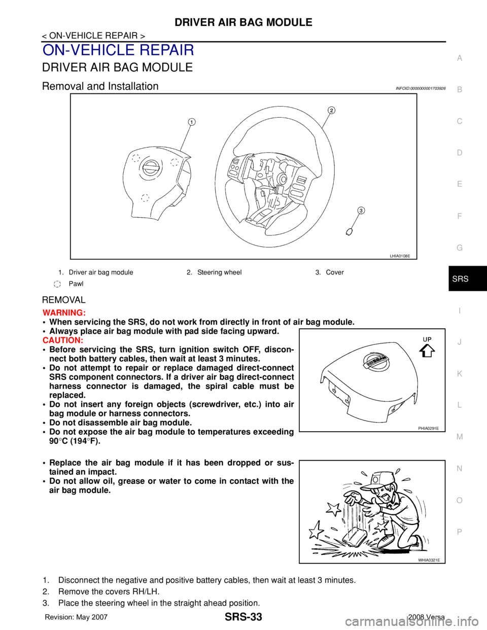
REMOVAL
WARNING:
• When servicing the SRS, do not work from directly in front of air bag module.
• Always place air bag module with pad side facing upward.
CAUTION:
• Before servicing the SRS, turn ignition switch OFF, discon-
nect both battery cables, then wait at least 3 minutes.
• Do not attempt to repair or replace damaged direct-connect
SRS component connectors. If a driver air bag direct-connect
harness connector is damaged, the spiral cable must be
replaced.
• Do not insert any foreign objects (screwdriver, etc.) into air
bag module or harness connectors.
• Do not disassemble air bag module.
• Do not expose the air bag module to temperatures exceeding
90°C (194°F).
• Replace the air bag module if it has been dropped or sus-
tained an impact.
• Do not allow oil, grease or water to come in contact with the
air bag module.
1. Disconnect the negative and positive battery cables, then wait at least 3 minutes.
2. Remove the covers RH/LH.
3. Place the steering wheel in the straight ahead position.
LHIA0108E
1. Driver air bag module 2. Steering wheel 3. Cover
Pawl
PHIA0291E
WHIA0321E
Page 2670 of 2771
SRS-36
< ON-VEHICLE REPAIR >
SPIRAL CABLE
SPIRAL CABLE
Removal and InstallationINFOID:0000000001703927
REMOVAL
WARNING:
When servicing the SRS, do not work from directly in front of air bag module.
CAUTION:
• Before servicing the SRS, turn ignition switch OFF, disconnect both battery cables and wait at least
3 minutes.
• Do not tap or bump the steering wheel.
• Do not disassemble the spiral cable.
• Do not allow oil, grease or water to come in contact with the spiral cable.
• Replace the spiral cable if it has been dropped or sustained an impact.
• With the steering linkage disconnected, the spiral cable may snap by turning the steering wheel
beyond the limited number of turns. The spiral cable can be turned counterclockwise about 2.5 turns
from the neutral position.
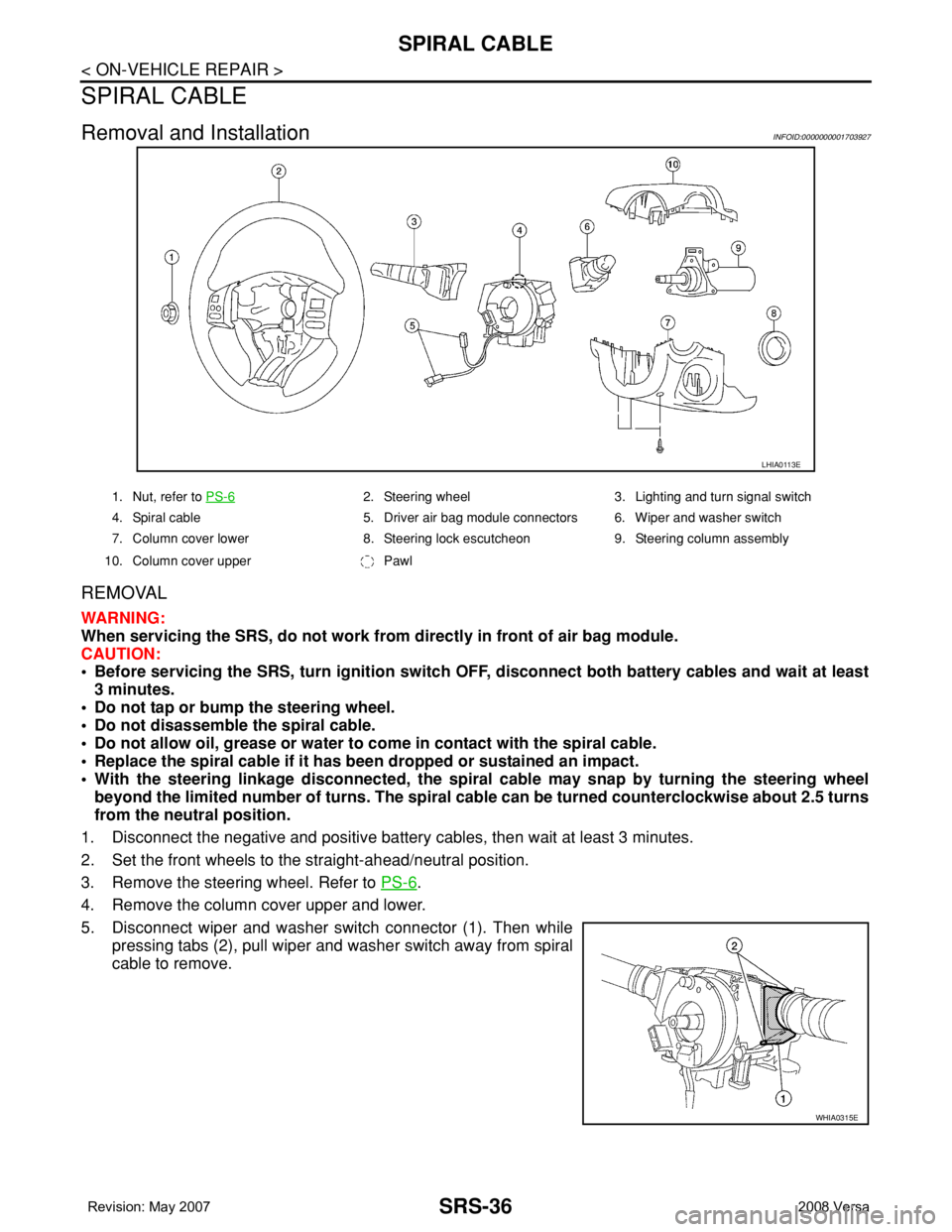
1. Disconnect the negative and positive battery cables, then wait at least 3 minutes.
2. Set the front wheels to the straight-ahead/neutral position.
3. Remove the steering wheel. Refer to PS-6
.
4. Remove the column cover upper and lower.
5. Disconnect wiper and washer switch connector (1). Then while
pressing tabs (2), pull wiper and washer switch away from spiral
cable to remove.
LHIA0113E
1. Nut, refer to PS-62. Steering wheel 3. Lighting and turn signal switch
4. Spiral cable 5. Driver air bag module connectors 6. Wiper and washer switch
7. Column cover lower 8. Steering lock escutcheon 9. Steering column assembly
10. Column cover upper Pawl
WHIA0315E
Page 2672 of 2771
SRS-38
< ON-VEHICLE REPAIR >
FRONT PASSENGER AIR BAG MODULE
FRONT PASSENGER AIR BAG MODULE
Removal and InstallationINFOID:0000000001703928
REMOVAL
WARNING:
• When servicing the SRS, do not work from directly in front of air bag module.
• Always place front passenger air bag module with pad side facing upward.
CAUTION:
• Before servicing SRS, turn the ignition switch OFF, disconnect both battery cables and wait at least
3 minutes.
• Do not use old bolts after removal; replace with new bolts.
• Do not insert any foreign objects (screwdriver, etc.) into air bag module or harness connectors.
• Do not disassemble air bag module.
• Do not expose the front passenger air bag module to temperatures exceeding 90°C (194°F).
• Replace the front passenger air bag module if it has been
dropped or sustained an impact.
• Do not allow oil, grease or water to come in contact with the
front passenger air bag module.
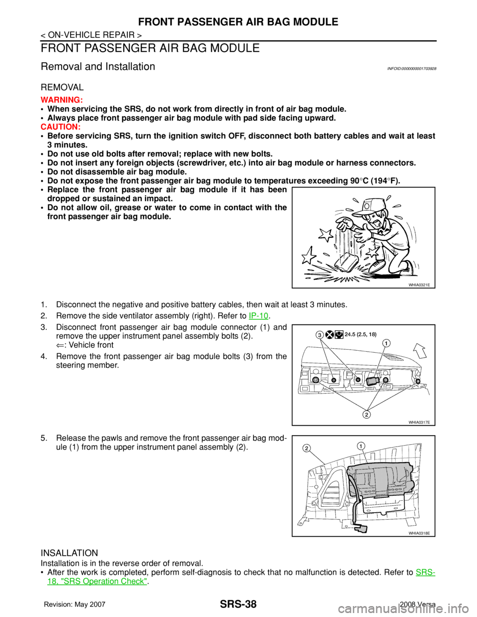
1. Disconnect the negative and positive battery cables, then wait at least 3 minutes.
2. Remove the side ventilator assembly (right). Refer to IP-10
.
3. Disconnect front passenger air bag module connector (1) and
remove the upper instrument panel assembly bolts (2).
⇐: Vehicle front
4. Remove the front passenger air bag module bolts (3) from the
steering member.
5. Release the pawls and remove the front passenger air bag mod-
ule (1) from the upper instrument panel assembly (2).
INSALLATION
Installation is in the reverse order of removal.
• After the work is completed, perform self-diagnosis to check that no malfunction is detected. Refer to SRS-
18, "SRS Operation Check".
WHIA0321E
WHIA0317E
WHIA0318E