2008 NISSAN TIIDA Water temperature gauge
[x] Cancel search: Water temperature gaugePage 826 of 2771
ENGINE COOLANT
CO-9
< SERVICE INFORMATION >
C
D
E
F
G
H
I
J
K
L
MA
CO
N
P O
1. Install reservoir tank if removed. Refer to CO-11.
2. Install radiator drain plug.
•If water drain plug on cylinder block is removed, close and tighten it. Refer to EM-76
.
CAUTION:
Be sure to clean radiator drain plug and install with new O-ring. Refer to CO-11, "
Component".
3. Make sure that each hose clamp has been firmly tightened.
4. Remove air duct assembly. Refer to EM-16
.
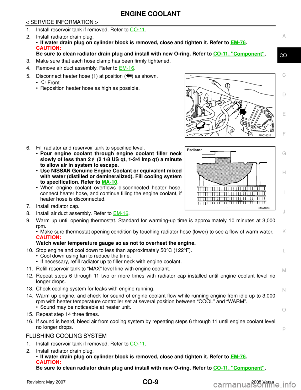
5. Disconnect heater hose (1) at position ( ) as shown.
• Front
• Reposition heater hose as high as possible.
6. Fill radiator and reservoir tank to specified level.
•Pour engine coolant through engine coolant filler neck
slowly of less than 2 (2 1/8 US qt, 1-3/4 lmp qt) a minute
to allow air in system to escape.
•Use NISSAN Genuine Engine Coolant or equivalent mixed
with water (distilled or demineralized). Fill cooling system
to specification. Refer to MA-10
.
• When engine coolant overflows disconnected heater hose,
connect heater hose, and continue filling the engine coolant, if
heater hose is disconnected.
7. Install radiator cap.
8. Install air duct assembly. Refer to EM-16
.
9. Warm up until opening thermostat. Standard for warming-up time is approximately 10 minutes at 3,000
rpm.
• Make sure thermostat opening condition by touching radiator hose (lower) to see a flow of warm water.
CAUTION:
Watch water temperature gauge so as not to overheat the engine.
10. Stop engine and cool down to less than approximately 50°C (122°F).
• Cool down using fan to reduce the time.
• If necessary, refill radiator up to filler neck with engine coolant.
11. Refill reservoir tank to “MAX” level line with engine coolant.
12. Repeat steps 6 through 11 two or more times with radiator cap installed until engine coolant level no
longer drops.
13. Check cooling system for leaks with engine running.
14. Warm up engine, and check for sound of engine coolant flow while running engine from idle up to 3,000
rpm with heater temperature controller set at several position between “COOL” and “WARM”.
• Sound may be noticeable at heater unit.
15. Repeat step 14 three times.
16. If sound is heard, bleed air from cooling system by repeating steps 6 through 11 until engine coolant level
no longer drops.
FLUSHING COOLING SYSTEM
1. Install reservoir tank if removed. Refer to CO-11.
2. Install radiator drain plug.
•If water drain plug on cylinder block is removed, close and tighten it. Refer to EM-76
.
CAUTION:
Be sure to clean radiator drain plug and install with new O-ring. Refer to CO-11, "
Component".
PBIC3802E
SMA182B
Page 1032 of 2771
COMBINATION METERS
DI-11
< SERVICE INFORMATION >
C
D
E
F
G
H
I
J
L
MA
B
DI
N
O
P
Self-Diagnosis Mode of Combination MeterINFOID:0000000001704497
SELF-DIAGNOSIS MODE FUNCTION
• Self-diagnosis can check for continuity between meter control circuit and each meter (speedometer, tachom-
eter and fuel gauge).
• Self-diagnosis can check for odo/trip meter and A/T indicator (with A/T) or CVT indicator (with CVT) seg-
ment, low-fuel level warning lamp, low water temperature indicator lamp, and high water temperature warn-
ing lamp.
OPERATION PROCEDURE
1. Turn the ignition switch ON, and switch the odo/trip meter to “trip A” or “trip B”.
NOTE:
13 B Illumination control switch (-) — — Refer to LT- 1 0 5 , "System Description" .
17 GWasher fluid level switch
(Canada models)ONWasher fluid level low 0
Washer fluid level normal Battery voltage
21
BGround — — 0 22
23
24 V Fuel level sensor ground (-) ON — 0
26 BVehicle speed sensor ground
(without ABS or CVT)ON — 0
27 G Battery power supply OFF — Battery voltage
28 SB Ignition switch ON or START ON — Battery voltage
29 GR Seat belt buckle switch RH ONUnfastened (ON) 0
Fastened (OFF) Battery voltage
30 G Stop lamp switch ONBrake pedal depressed Battery voltage
Brake pedal released 0
31 V A/T N-range input (with A/T) ONTransmission gear selector lever
in N positionBattery voltage
Transmission gear selector lever
other than N position0
32 W A/T P-range input (with A/T) ONTransmission gear selector lever
in P positionBattery voltage
Transmission gear selector lever
other than P position0
33 Y A/T PN output (with A/T) ONTransmission gear selector lever
in P or N position0
Transmission gear selector lever
other than P or N positionBattery voltage
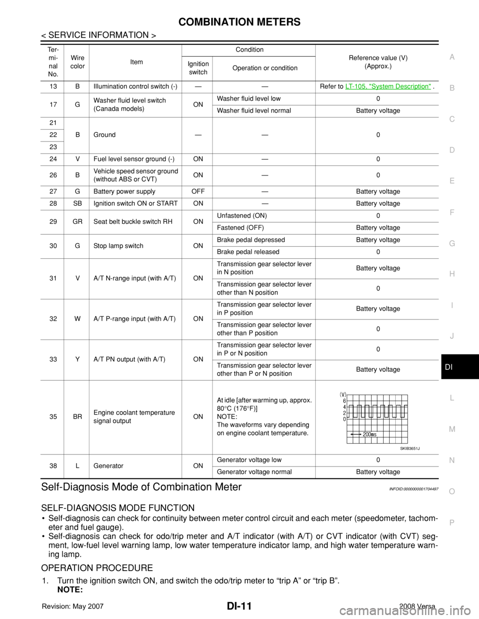
35 BREngine coolant temperature
signal outputONAt idle [after warming up, approx.
80°C (176°F)]
NOTE:
The waveforms vary depending
on engine coolant temperature.
38 L Generator ONGenerator voltage low 0
Generator voltage normal Battery voltage Te r -
mi-
nal
No.Wire
colorItemCondition
Reference value (V)
(Approx.) Ignition
switchOperation or condition
SKIB3651J
Page 1498 of 2771
EC-424
< SERVICE INFORMATION >
DTC P1217 ENGINE OVER TEMPERATURE
OK >> GO TO 6.
NG >> Replace cooling fan motor.
6.CHECK INTERMITTENT INCIDENT
Perform EC-136
.
OK or NG
OK >> Replace IPDM E/R. Refer to PG-26, "Removal and Installation of IPDM E/R".
NG >> Repair or replace harness or connector.
Main 13 Causes of OverheatingINFOID:0000000001702935
*1: Turn the ignition switch ON.
*2: Engine running at 3,000 rpm for 10 minutes.
*3: Drive at 90 km/h (55 MPH) for 30 minutes and then let idle for 10 minutes.
*4: After 60 minutes of cool down time.
For more information, refer to CO-5
.
Component InspectionINFOID:0000000001702936
COOLING FAN MOTOR
Model with A/C
Engine Step Inspection item Equipment Standard Reference page
OFF 1 • Blocked radiator
• Blocked condenser
• Blocked radiator grille
• Blocked bumper• Visual No blocking —
2 • Coolant mixture • Coolant tester 50 - 50% coolant mixture See MA-11, "
Anti-freeze
Coolant Mixture Ratio".
3 • Coolant level • Visual Coolant up to MAX level in
reservoir tank and radiator
filler neckSee CO-8, "
Inspection".
4 • Radiator cap • Pressure tester 59 - 98 kPa
(0.6 - 1.0 kg/cm
2, 9 - 14
psi) (Limit)See CO-13, "
Checking
Radiator Cap".
ON*
25 • Coolant leaks • Visual No leaks See CO-8, "Inspection".
ON*
26 • Thermostat • Touch the upper and
lower radiator hosesBoth hoses should be hot See CO-17, and CO-11
ON*17 • Cooling fan • CONSULT-II Operating See trouble diagnosis for
DTC P1217 (EC-417, "
Di-
agnosis Procedure").
OFF 8 • Combustion gas leak • Color checker chemical
tester 4 Gas analyzerNegative —
ON*
39 • Coolant temperature
gauge• Visual Gauge less than 3/4 when
driving—
• Coolant overflow to res-
ervoir tank• Visual No overflow during driving
and idlingSee CO-8, "
Changing En-
gine Coolant".
OFF*
410 • Coolant return from res-
ervoir tank to radiator• Visual Should be initial level in
reservoir tankSee CO-8, "Inspection".
OFF 11 • Water control valve• Remove and inspect
the valveWithin the specified valueSee CO-19, "
Removal
and Installation"
OFF 12 • Cylinder head • Straight gauge feeler
gauge0.1 mm (0.004 in) Maxi-
mum distortion (warping)See EM-62.
13 • Cylinder block and pis-
tons• Visual No scuffing on cylinder
walls or pistonSee EM-76
.
Page 2273 of 2771
ENGINE MAINTENANCE
MA-13
< SERVICE INFORMATION >
C
D
E
F
G
H
I
J
K
MA
B
MA
N
O
P
2. Remove reservoir tank as necessary, and drain engine coolant and clean reservoir tank before installing.
Refer to CO-11
.
3. Check drained engine coolant for contaminants such as rust, corrosion or discoloration.
If contaminated, flush the engine cooling system. Refer to "FLUSHING COOLING SYSTEM" .
REFILLING ENGINE COOLANT
1. Install reservoir tank if removed. Refer to CO-11 .
2. Install radiator drain plug.
•If water drain plug on cylinder block is removed, close and tighten it. Refer to EM-76
.
CAUTION:
Be sure to clean radiator drain plug and install with new O-ring. Refer to CO-11, "
Component" .
3. Make sure that each hose clamp has been firmly tightened.
4. Remove air duct assembly. Refer to EM-16
.
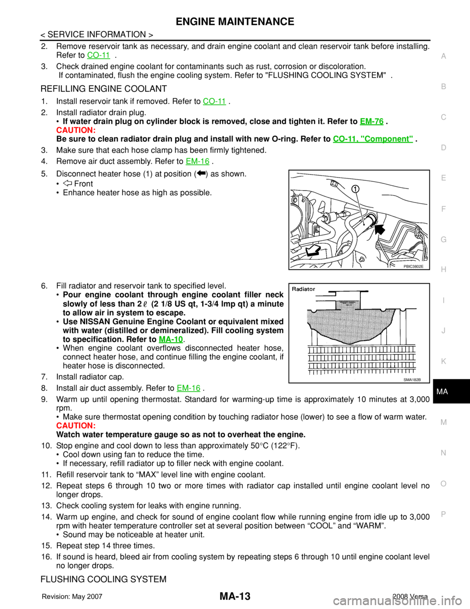
5. Disconnect heater hose (1) at position ( ) as shown.
• Front
• Enhance heater hose as high as possible.
6. Fill radiator and reservoir tank to specified level.
•Pour engine coolant through engine coolant filler neck
slowly of less than 2 (2 1/8 US qt, 1-3/4 lmp qt) a minute
to allow air in system to escape.
•Use NISSAN Genuine Engine Coolant or equivalent mixed
with water (distilled or demineralized). Fill cooling system
to specification. Refer to MA-10
.
• When engine coolant overflows disconnected heater hose,
connect heater hose, and continue filling the engine coolant, if
heater hose is disconnected.
7. Install radiator cap.
8. Install air duct assembly. Refer to EM-16
.
9. Warm up until opening thermostat. Standard for warming-up time is approximately 10 minutes at 3,000
rpm.
• Make sure thermostat opening condition by touching radiator hose (lower) to see a flow of warm water.
CAUTION:
Watch water temperature gauge so as not to overheat the engine.
10. Stop engine and cool down to less than approximately 50°C (122°F).
• Cool down using fan to reduce the time.
• If necessary, refill radiator up to filler neck with engine coolant.
11. Refill reservoir tank to “MAX” level line with engine coolant.
12. Repeat steps 6 through 10 two or more times with radiator cap installed until engine coolant level no
longer drops.
13. Check cooling system for leaks with engine running.
14. Warm up engine, and check for sound of engine coolant flow while running engine from idle up to 3,000
rpm with heater temperature controller set at several position between “COOL” and “WARM”.
• Sound may be noticeable at heater unit.
15. Repeat step 14 three times.
16. If sound is heard, bleed air from cooling system by repeating steps 6 through 10 until engine coolant level
no longer drops.
FLUSHING COOLING SYSTEM
PBIC3802E
SMA182B
Page 2388 of 2771
MTC-50
< SERVICE INFORMATION >
TROUBLE DIAGNOSIS
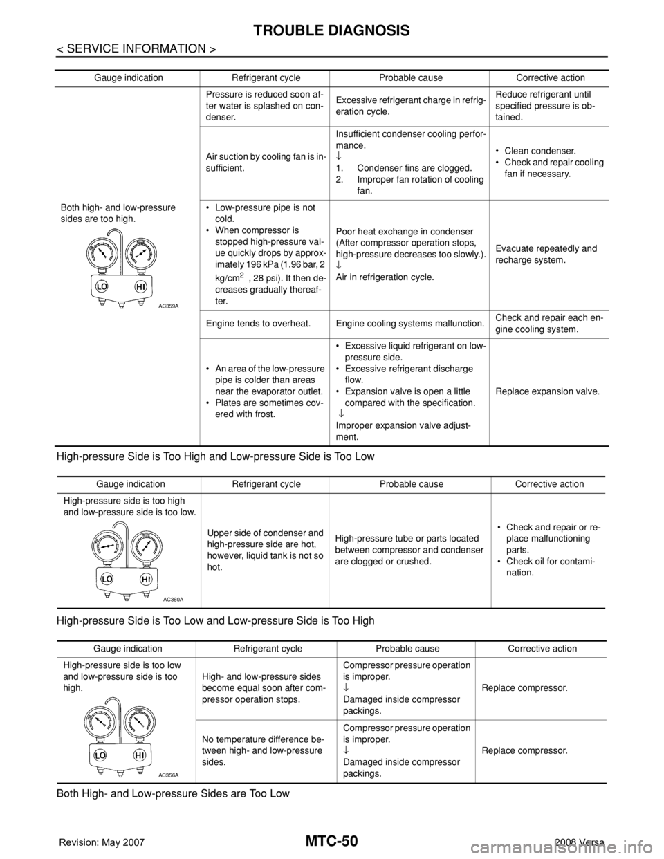
High-pressure Side is Too High and Low-pressure Side is Too Low
High-pressure Side is Too Low and Low-pressure Side is Too High
Both High- and Low-pressure Sides are Too Low
Gauge indication Refrigerant cycle Probable cause Corrective action
Both high- and low-pressure
sides are too high.Pressure is reduced soon af-
ter water is splashed on con-
denser.Excessive refrigerant charge in refrig-
eration cycle.Reduce refrigerant until
specified pressure is ob-
tained.
Air suction by cooling fan is in-
sufficient.Insufficient condenser cooling perfor-
mance.
↓
1. Condenser fins are clogged.
2. Improper fan rotation of cooling
fan.• Clean condenser.
• Check and repair cooling
fan if necessary.
• Low-pressure pipe is not
cold.
• When compressor is
stopped high-pressure val-
ue quickly drops by approx-
imately 196 kPa (1.96 bar, 2
kg/cm
2 , 28 psi). It then de-
creases gradually thereaf-
ter.Poor heat exchange in condenser
(After compressor operation stops,
high-pressure decreases too slowly.).
↓
Air in refrigeration cycle.Evacuate repeatedly and
recharge system.
Engine tends to overheat. Engine cooling systems malfunction.Check and repair each en-
gine cooling system.
• An area of the low-pressure
pipe is colder than areas
near the evaporator outlet.
• Plates are sometimes cov-
ered with frost.• Excessive liquid refrigerant on low-
pressure side.
• Excessive refrigerant discharge
flow.
• Expansion valve is open a little
compared with the specification.
↓
Improper expansion valve adjust-
ment.Replace expansion valve.
AC359A
Gauge indication Refrigerant cycle Probable cause Corrective action
High-pressure side is too high
and low-pressure side is too low.
Upper side of condenser and
high-pressure side are hot,
however, liquid tank is not so
hot.High-pressure tube or parts located
between compressor and condenser
are clogged or crushed.• Check and repair or re-
place malfunctioning
parts.
• Check oil for contami-
nation.
AC360A
Gauge indication Refrigerant cycle Probable cause Corrective action
High-pressure side is too low
and low-pressure side is too
high.High- and low-pressure sides
become equal soon after com-
pressor operation stops.Compressor pressure operation
is improper.
↓
Damaged inside compressor
packings.Replace compressor.
No temperature difference be-
tween high- and low-pressure
sides.Compressor pressure operation
is improper.
↓
Damaged inside compressor
packings.Replace compressor.
AC356A
Page 2389 of 2771
TROUBLE DIAGNOSIS
MTC-51
< SERVICE INFORMATION >
C
D
E
F
G
H
I
K
L
MA
B
MTC
N
O
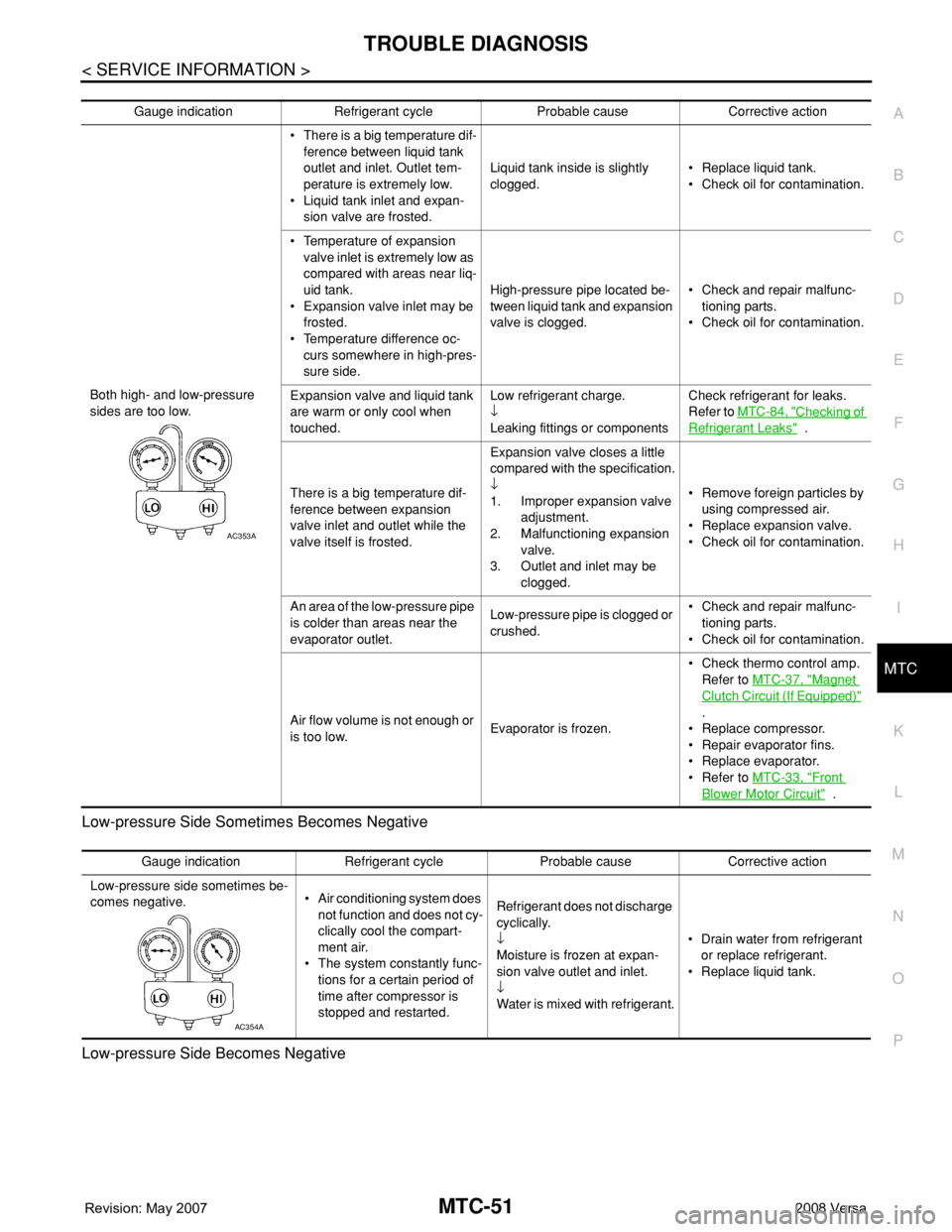
P Low-pressure Side Sometimes Becomes Negative
Low-pressure Side Becomes Negative
Gauge indication Refrigerant cycle Probable cause Corrective action
Both high- and low-pressure
sides are too low.• There is a big temperature dif-
ference between liquid tank
outlet and inlet. Outlet tem-
perature is extremely low.
• Liquid tank inlet and expan-
sion valve are frosted.Liquid tank inside is slightly
clogged.• Replace liquid tank.
• Check oil for contamination.
• Temperature of expansion
valve inlet is extremely low as
compared with areas near liq-
uid tank.
• Expansion valve inlet may be
frosted.
• Temperature difference oc-
curs somewhere in high-pres-
sure side.High-pressure pipe located be-
tween liquid tank and expansion
valve is clogged.• Check and repair malfunc-
tioning parts.
• Check oil for contamination.
Expansion valve and liquid tank
are warm or only cool when
touched.Low refrigerant charge.
↓
Leaking fittings or componentsCheck refrigerant for leaks.
Refer to MTC-84, "
Checking of
Refrigerant Leaks" .
There is a big temperature dif-
ference between expansion
valve inlet and outlet while the
valve itself is frosted.Expansion valve closes a little
compared with the specification.
↓
1. Improper expansion valve
adjustment.
2. Malfunctioning expansion
valve.
3. Outlet and inlet may be
clogged.• Remove foreign particles by
using compressed air.
• Replace expansion valve.
• Check oil for contamination.
An area of the low-pressure pipe
is colder than areas near the
evaporator outlet.Low-pressure pipe is clogged or
crushed.• Check and repair malfunc-
tioning parts.
• Check oil for contamination.
Air flow volume is not enough or
is too low.Evaporator is frozen.• Check thermo control amp.
Refer to MTC-37, "
Magnet
Clutch Circuit (If Equipped)"
.
• Replace compressor.
• Repair evaporator fins.
• Replace evaporator.
• Refer to MTC-33, "
Front
Blower Motor Circuit" .
AC353A
Gauge indication Refrigerant cycle Probable cause Corrective action
Low-pressure side sometimes be-
comes negative.• Air conditioning system does
not function and does not cy-
clically cool the compart-
ment air.
• The system constantly func-
tions for a certain period of
time after compressor is
stopped and restarted.Refrigerant does not discharge
cyclically.
↓
Moisture is frozen at expan-
sion valve outlet and inlet.
↓
Water is mixed with refrigerant.• Drain water from refrigerant
or replace refrigerant.
• Replace liquid tank.
AC354A
Page 2390 of 2771
MTC-52
< SERVICE INFORMATION >
TROUBLE DIAGNOSIS
Insufficient Heating
INFOID:0000000001704307
SYMPTOM: Insufficient heating
INSPECTION FLOW
1.CONFIRM SYMPTOM BY PERFORMING OPERATIONAL CHECK - TEMPERATURE DECREASE
1. Turn temperature control dial clockwise to maximum heat position.
2. Check for hot air at discharge air outlets.
Can the symptom be duplicated?
YES >> GO TO 3.
NO >> GO TO 2.
2.CHECK FOR ANY SYMPTOMS
Perform a complete operational check for any symptoms. Refer to MTC-30, "
Operational Check" .
Does another symptom exist?
YES >> Refer to MTC-22, "How to Perform Trouble Diagnosis for Quick and Accurate Repair" .
NO >> System OK.
3.CHECK FOR SERVICE BULLETINS
Check for any service bulletins.
>> GO TO 4.
4.CHECK COOLANT SYSTEM
1. Check engine coolant level. Refer to CO-8
.
2. Check hoses for leaks or kinks.
3. Check Radiator cap. Refer to CO-13, "
Checking Radiator Cap" .
OK or NG
OK >> GO TO 5.
NG >> Repair/replace as necessary.
5.CHECK AIR MIX DOOR CABLE
Check air mix door cable operation. Refer to MTC-64, "
Air Mix Door Cable Adjustment" .
OK or NG
YES >> GO TO 6.
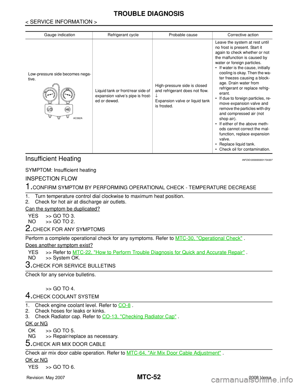
Gauge indication Refrigerant cycle Probable cause Corrective action
Low-pressure side becomes nega-
tive.
Liquid tank or front/rear side of
expansion valve’s pipe is frost-
ed or dewed.High-pressure side is closed
and refrigerant does not flow.
↓
Expansion valve or liquid tank
is frosted.Leave the system at rest until
no frost is present. Start it
again to check whether or not
the malfunction is caused by
water or foreign particles.
• If water is the cause, initially
cooling is okay. Then the wa-
ter freezes causing a block-
age. Drain water from
refrigerant or replace refrig-
erant.
• If due to foreign particles, re-
move expansion valve and
remove the particles with dry
and compressed air (not
shop air).
• If either of the above meth-
ods cannot correct the mal-
function, replace expansion
valve.
• Replace liquid tank.
• Check oil for contamination.
AC362A
Page 2425 of 2771
REFRIGERANT LINES
MTC-87
< SERVICE INFORMATION >
C
D
E
F
G
H
I
K
L
MA
B
MTC
N
O
P
Check all around the service valves. Ensure service valve caps are secured on the service valves (to
prevent leaks).
NOTE:
After removing A/C manifold gauge set from service valves, wipe any residue from valves to prevent any
false readings by leak detector.
• Cooling unit (Evaporator)
With engine OFF, turn blower fan on “High” for at least 15 seconds to dissipate any refrigerant trace in
the cooling unit. Wait a minimum of 10 minutes accumulation time (refer to the manufacturer’s recom-
mended procedure for actual wait time) before inserting the leak detector probe into the drain hose.
Keep the probe inserted for at least 10 seconds. Use caution not to contaminate the probe tip with water
or dirt that may be in the drain hose.
5. If a leak detector detects a leak, verify at least once by blowing compressed air into area of suspected
leak, then repeat check as outlined above.
6. Do not stop when one leak is found. Continue to check for additional leaks at all system components.
If no leaks are found, perform steps 7-10.
7. Start engine.
8. Set the heater A/C control as follows;
a. A/C switch: ON
b. Mode control dial position: VENT (Ventilation)
c. Intake door lever position: Recirculation
d. Max. cold temperature
e. Fan speed: High
9. Run engine at 1,500 rpm for at least 2 minutes.
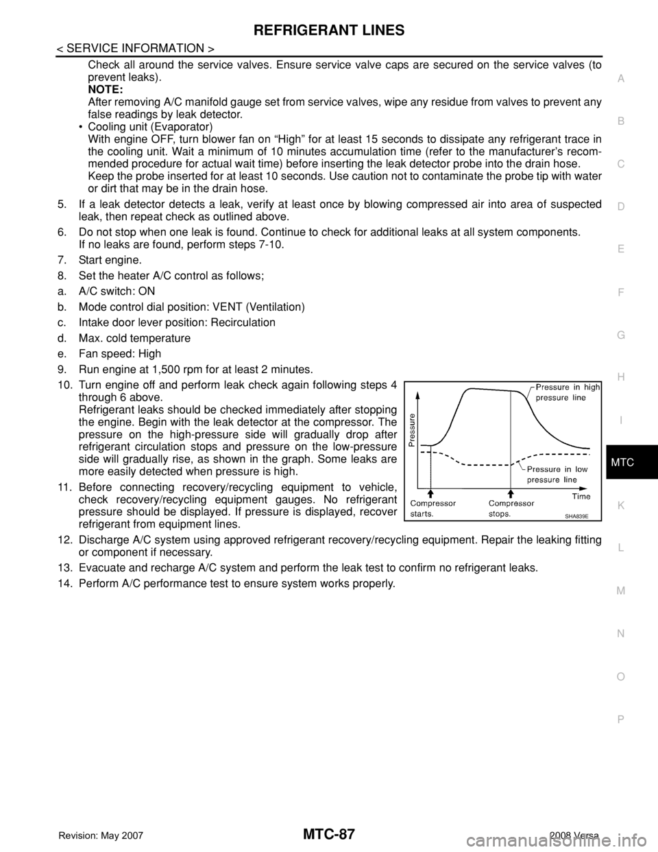
10. Turn engine off and perform leak check again following steps 4
through 6 above.
Refrigerant leaks should be checked immediately after stopping
the engine. Begin with the leak detector at the compressor. The
pressure on the high-pressure side will gradually drop after
refrigerant circulation stops and pressure on the low-pressure
side will gradually rise, as shown in the graph. Some leaks are
more easily detected when pressure is high.
11. Before connecting recovery/recycling equipment to vehicle,
check recovery/recycling equipment gauges. No refrigerant
pressure should be displayed. If pressure is displayed, recover
refrigerant from equipment lines.
12. Discharge A/C system using approved refrigerant recovery/recycling equipment. Repair the leaking fitting
or component if necessary.
13. Evacuate and recharge A/C system and perform the leak test to confirm no refrigerant leaks.
14. Perform A/C performance test to ensure system works properly.
SHA839E