2008 NISSAN TIIDA PN switch
[x] Cancel search: PN switchPage 2590 of 2771

SC-8
< SERVICE INFORMATION >
STARTING SYSTEM
STARTING SYSTEM
System DescriptionINFOID:0000000001704348
M/T Models
Power is supplied at all times
• to starter motor terminal B, and
• through 40A fusible link (letter h , located in the fuse and fusible link box)
• to ignition switch terminal B.
With the ignition switch in the START position, power is supplied
• from ignition switch terminal ST
• to IPDM E/R terminal 21.
With the ignition switch in the ON or START position, power is supplied
• through 10A fuse (No. 49, located in the IPDM E/R)
• to the clutch interlock switch terminal 1.
With the clutch pedal depressed, power is supplied
• through the clutch interlock switch terminal 2
• to IPDM E/R terminal 35.
Ground is supplied at all times
• to IPDM E/R terminals 39 and 59
• through body grounds E15 and E24.
If the IPDM E/R receives a starter relay request ON signal from the BCM over the CAN communication lines,
the IPDM E/R grounds the starter relay and power is supplied
• through terminal 19 of the IPDM E/R
• to terminal S of the starter motor.
The starter motor magnetic switch energizes closing the circuit between the battery and the starter motor. The
starter motor is case ground through the cylinder block. With power and ground supplied, the starter motor
operates.
A/T Models
Power is supplied at all times
• to starter motor terminal B, and
• through 40A fusible link (letter h , located in the fuse and fusible link box)
• to ignition switch terminal B.
With the ignition switch in the START position, power is supplied
• from ignition switch terminal ST
• to IPDM E/R terminal 21.
With the ignition switch in the ON or START position, power is supplied
• through 10A fuse (No. 54, located in the IPDM E/R)
• to park/neutral position (PNP) switch terminal 1.
With the selector lever in the P or N position, power is supplied
• through PNP switch terminal 2
• to IPDM E/R terminal 35.
Ground is supplied at all times
• to IPDM E/R terminals 39 and 59
• through body grounds E15 and E24.
If the IPDM E/R receives a starter relay request ON signal from the BCM over the CAN communication lines,
the IPDM E/R grounds the starter relay and power is supplied
• through terminal 19 of the IPDM E/R
• to terminal S of the starter motor.
The starter motor magnetic switch energizes closing the circuit between the battery and the starter motor. The
starter motor is case ground through the cylinder block. With power and ground supplied, the starter motor
operates.
CVT Models
Power is supplied at all times
• to starter motor terminal B, and
• through 40A fusible link (letter h , located in the fuse and fusible link box)
• to ignition switch terminal B.
With the ignition switch in the START position, power is supplied
• from ignition switch terminal ST
Page 2591 of 2771

STARTING SYSTEM
SC-9
< SERVICE INFORMATION >
C
D
E
F
G
H
I
J
L
MA
B
SC
N
O
P
• to IPDM E/R terminal 21.
With the selector lever in the P or N position, power is supplied
• from the transmission control module (TCM) terminal 24
• to IPDM E/R terminal 35.
Ground is supplied at all times
• to IPDM E/R terminals 39 and 59
• through body grounds E15 and E24.
If the IPDM E/R receives a starter relay request ON signal from the BCM over the CAN network, the IPDM E/
R grounds the starter relay and power is supplied
• through terminal 19 of the IPDM E/R
• to terminal S of the starter motor.
The starter motor magnetic switch energizes closing the circuit between the battery and the starter motor. The
starter motor is case ground through the cylinder block. With power and ground supplied, the starter motor
operates.
Page 2598 of 2771
SC-16
< SERVICE INFORMATION >
STARTING SYSTEM
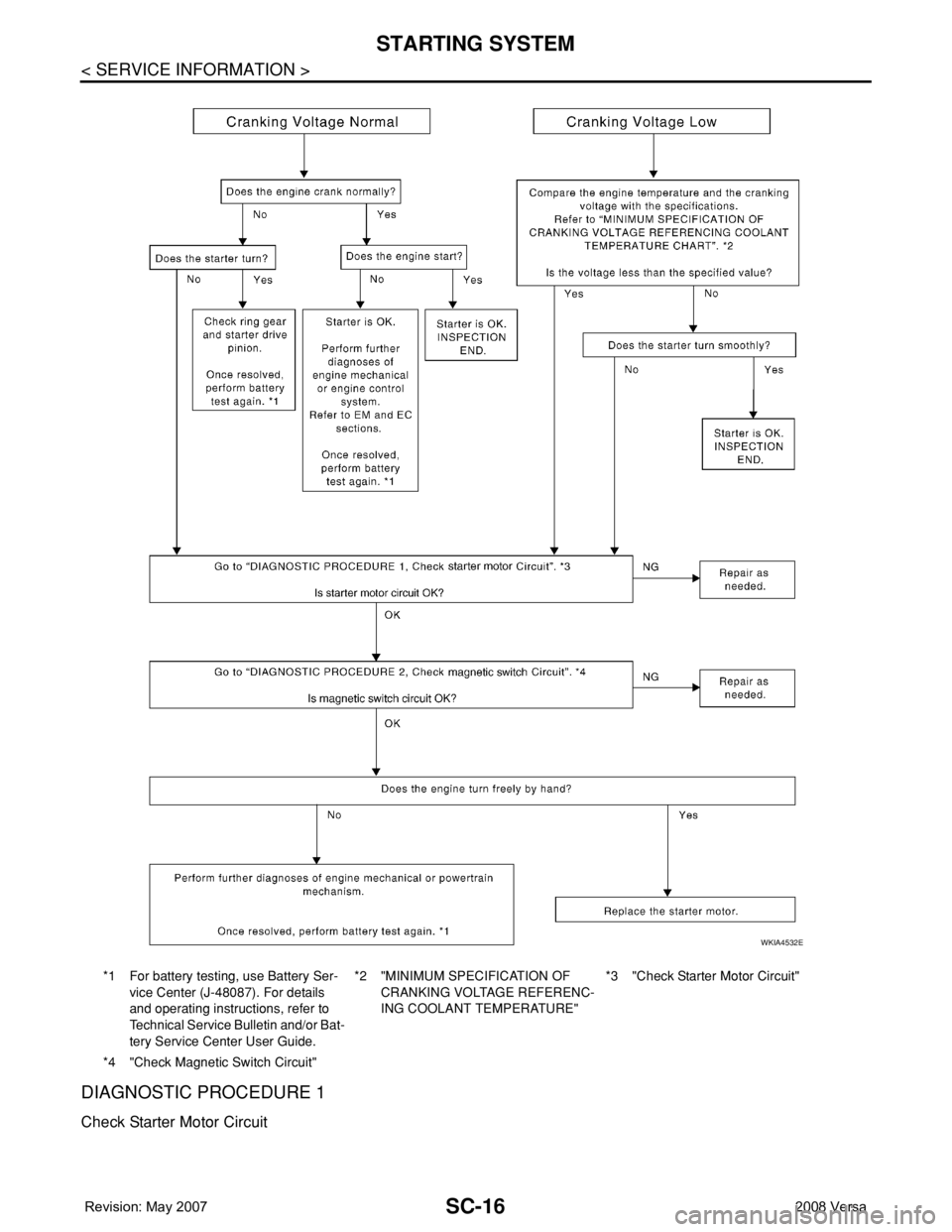
DIAGNOSTIC PROCEDURE 1
Check Starter Motor Circuit
*1 For battery testing, use Battery Ser-
vice Center (J-48087). For details
and operating instructions, refer to
Technical Service Bulletin and/or Bat-
tery Service Center User Guide.*2 "MINIMUM SPECIFICATION OF
CRANKING VOLTAGE REFERENC-
ING COOLANT TEMPERATURE"*3 "Check Starter Motor Circuit"
*4 "Check Magnetic Switch Circuit"
WKIA4532E
Page 2599 of 2771
STARTING SYSTEM
SC-17
< SERVICE INFORMATION >
C
D
E
F
G
H
I
J
L
MA
B
SC
N
O
P
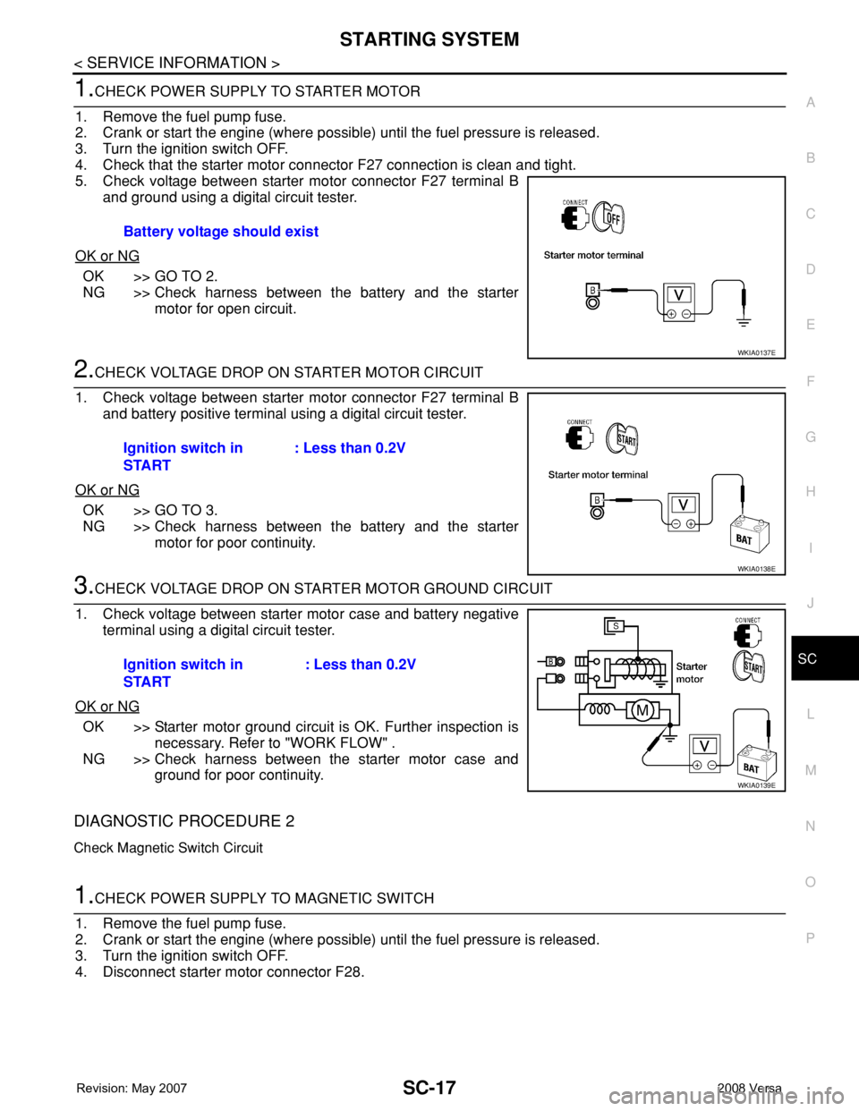
1.CHECK POWER SUPPLY TO STARTER MOTOR
1. Remove the fuel pump fuse.
2. Crank or start the engine (where possible) until the fuel pressure is released.
3. Turn the ignition switch OFF.
4. Check that the starter motor connector F27 connection is clean and tight.
5. Check voltage between starter motor connector F27 terminal B
and ground using a digital circuit tester.
OK or NG
OK >> GO TO 2.
NG >> Check harness between the battery and the starter
motor for open circuit.
2.CHECK VOLTAGE DROP ON STARTER MOTOR CIRCUIT
1. Check voltage between starter motor connector F27 terminal B
and battery positive terminal using a digital circuit tester.
OK or NG
OK >> GO TO 3.
NG >> Check harness between the battery and the starter
motor for poor continuity.
3.CHECK VOLTAGE DROP ON STARTER MOTOR GROUND CIRCUIT
1. Check voltage between starter motor case and battery negative
terminal using a digital circuit tester.
OK or NG
OK >> Starter motor ground circuit is OK. Further inspection is
necessary. Refer to "WORK FLOW" .
NG >> Check harness between the starter motor case and
ground for poor continuity.
DIAGNOSTIC PROCEDURE 2
Check Magnetic Switch Circuit
1.CHECK POWER SUPPLY TO MAGNETIC SWITCH
1. Remove the fuel pump fuse.
2. Crank or start the engine (where possible) until the fuel pressure is released.
3. Turn the ignition switch OFF.
4. Disconnect starter motor connector F28.Battery voltage should exist
WKIA0137E
Ignition switch in
START: Less than 0.2V
WKIA0138E
Ignition switch in
START: Less than 0.2V
WKIA0139E
Page 2600 of 2771
SC-18
< SERVICE INFORMATION >
STARTING SYSTEM
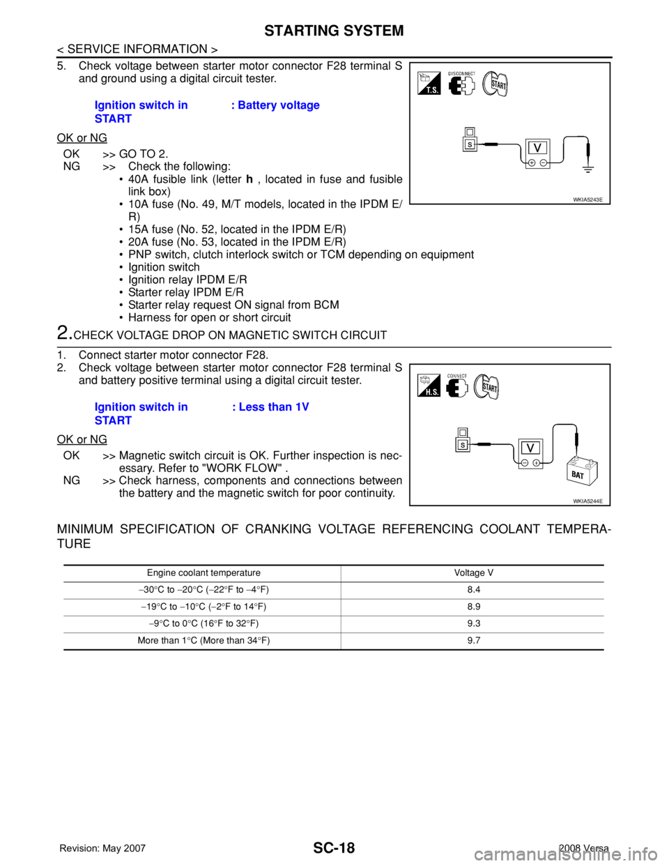
5. Check voltage between starter motor connector F28 terminal S
and ground using a digital circuit tester.
OK or NG
OK >> GO TO 2.
NG >> Check the following:
• 40A fusible link (letter h , located in fuse and fusible
link box)
• 10A fuse (No. 49, M/T models, located in the IPDM E/
R)
• 15A fuse (No. 52, located in the IPDM E/R)
• 20A fuse (No. 53, located in the IPDM E/R)
• PNP switch, clutch interlock switch or TCM depending on equipment
• Ignition switch
• Ignition relay IPDM E/R
• Starter relay IPDM E/R
• Starter relay request ON signal from BCM
• Harness for open or short circuit
2.CHECK VOLTAGE DROP ON MAGNETIC SWITCH CIRCUIT
1. Connect starter motor connector F28.
2. Check voltage between starter motor connector F28 terminal S
and battery positive terminal using a digital circuit tester.
OK or NG
OK >> Magnetic switch circuit is OK. Further inspection is nec-
essary. Refer to "WORK FLOW" .
NG >> Check harness, components and connections between
the battery and the magnetic switch for poor continuity.
MINIMUM SPECIFICATION OF CRANKING VOLTAGE REFERENCING COOLANT TEMPERA-
TURE
Ignition switch in
START: Battery voltage
WKIA5243E
Ignition switch in
START: Less than 1V
WKIA5244E
Engine coolant temperature Voltage V
−30°C to −20°C (−22°F to −4°F) 8.4
−19°C to −10°C (−2°F to 14°F) 8.9
−9°C to 0°C (16°F to 32°F) 9.3
More than 1°C (More than 34°F) 9.7
Page 2602 of 2771

SC-20
< SERVICE INFORMATION >
CHARGING SYSTEM
CHARGING SYSTEM
System DescriptionINFOID:0000000001704352
The generator provides DC voltage to operate the vehicle's electrical system and to keep the battery charged.
The voltage output is controlled by the IC regulator.
Power is supplied at all times to generator terminal 3 through
• 10A fuse (No. 29, located in the fuse and fusible link box).
Power is supplied through terminal 1 to charge the battery and operate the vehicle's electrical system. Output
voltage is monitored at terminal 3 by the IC regulator. The charging circuit is protected by the 120A fusible link
[letter a , located in the fusible link box (battery)].
Ground is supplied
• to generator terminal 5
• through body ground F5, and
• through the generator case to the cylinder block
With the ignition switch in the ON or START position, power is supplied
• through 10A fuse [No. 3, located in the fuse block (J/B)]
• to combination meter terminal 28 for the charge warning lamp.
The IC regulator controls ground to terminal 38 of the combination meter through terminal 2 of the generator.
When the ignition is turned on and power becomes available at terminal 2, this "wakes up" the regulator. The
regulator monitors charge output and grounds terminal 2 or leaves it open depending on charge output. With
power and ground supplied, the charge warning lamp will illuminate. When the generator is providing sufficient
voltage, the ground is opened and the charge warning lamp will go off.
If the charge warning lamp illuminates with the engine running, a malfunction is indicated.
Page 2605 of 2771
CHARGING SYSTEM
SC-23
< SERVICE INFORMATION >
C
D
E
F
G
H
I
J
L
MA
B
SC
N
O
P
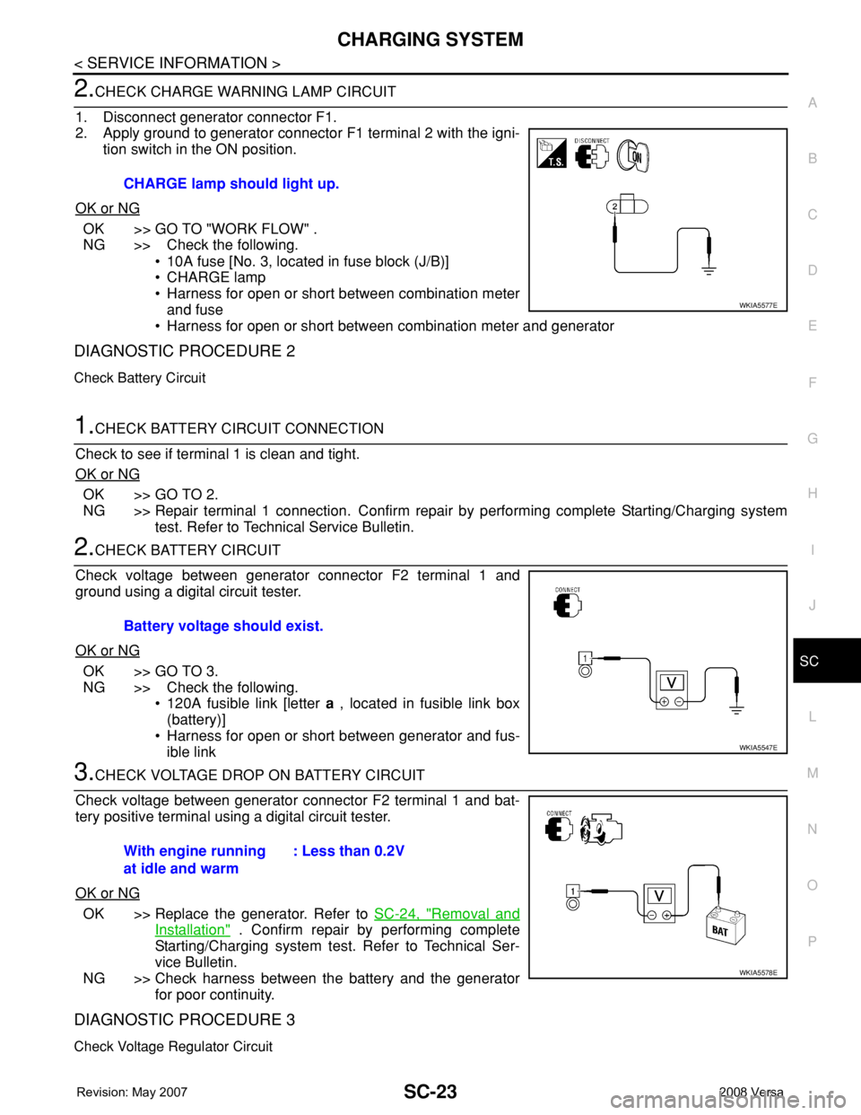
2.CHECK CHARGE WARNING LAMP CIRCUIT
1. Disconnect generator connector F1.
2. Apply ground to generator connector F1 terminal 2 with the igni-
tion switch in the ON position.
OK or NG
OK >> GO TO "WORK FLOW" .
NG >> Check the following.
• 10A fuse [No. 3, located in fuse block (J/B)]
• CHARGE lamp
• Harness for open or short between combination meter
and fuse
• Harness for open or short between combination meter and generator
DIAGNOSTIC PROCEDURE 2
Check Battery Circuit
1.CHECK BATTERY CIRCUIT CONNECTION
Check to see if terminal 1 is clean and tight.
OK or NG
OK >> GO TO 2.
NG >> Repair terminal 1 connection. Confirm repair by performing complete Starting/Charging system
test. Refer to Technical Service Bulletin.
2.CHECK BATTERY CIRCUIT
Check voltage between generator connector F2 terminal 1 and
ground using a digital circuit tester.
OK or NG
OK >> GO TO 3.
NG >> Check the following.
• 120A fusible link [letter a , located in fusible link box
(battery)]
• Harness for open or short between generator and fus-
ible link
3.CHECK VOLTAGE DROP ON BATTERY CIRCUIT
Check voltage between generator connector F2 terminal 1 and bat-
tery positive terminal using a digital circuit tester.
OK or NG
OK >> Replace the generator. Refer to SC-24, "Removal and
Installation" . Confirm repair by performing complete
Starting/Charging system test. Refer to Technical Ser-
vice Bulletin.
NG >> Check harness between the battery and the generator
for poor continuity.
DIAGNOSTIC PROCEDURE 3
Check Voltage Regulator Circuit
CHARGE lamp should light up.
WKIA5577E
Battery voltage should exist.
WKIA5547E
With engine running
at idle and warm: Less than 0.2V
WKIA5578E
Page 2620 of 2771
SE-12
< SERVICE INFORMATION >
FRONT SEAT
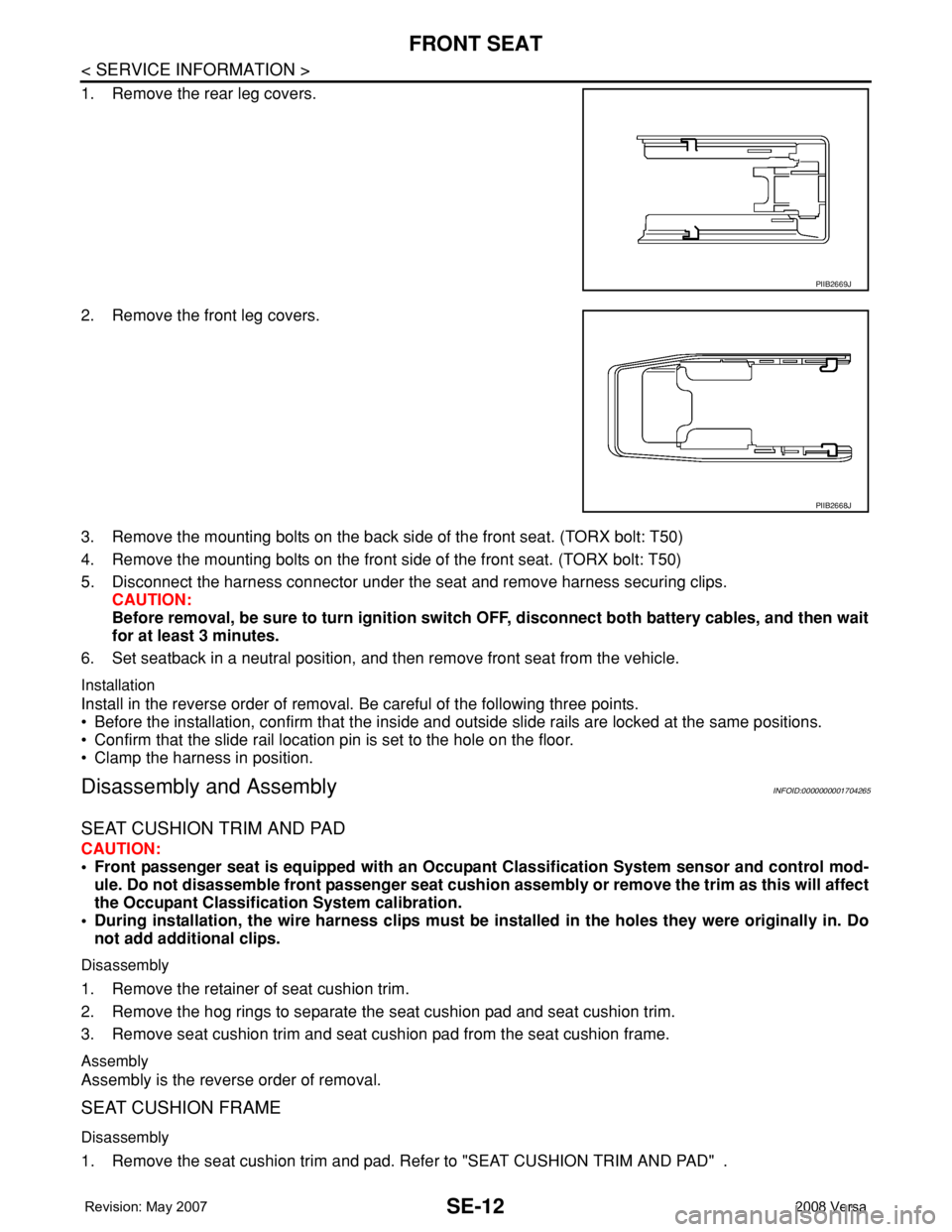
1. Remove the rear leg covers.
2. Remove the front leg covers.
3. Remove the mounting bolts on the back side of the front seat. (TORX bolt: T50)
4. Remove the mounting bolts on the front side of the front seat. (TORX bolt: T50)
5. Disconnect the harness connector under the seat and remove harness securing clips.
CAUTION:
Before removal, be sure to turn ignition switch OFF, disconnect both battery cables, and then wait
for at least 3 minutes.
6. Set seatback in a neutral position, and then remove front seat from the vehicle.
Installation
Install in the reverse order of removal. Be careful of the following three points.
• Before the installation, confirm that the inside and outside slide rails are locked at the same positions.
• Confirm that the slide rail location pin is set to the hole on the floor.
• Clamp the harness in position.
Disassembly and AssemblyINFOID:0000000001704265
SEAT CUSHION TRIM AND PAD
CAUTION:
• Front passenger seat is equipped with an Occupant Classification System sensor and control mod-
ule. Do not disassemble front passenger seat cushion assembly or remove the trim as this will affect
the Occupant Classification System calibration.
• During installation, the wire harness clips must be installed in the holes they were originally in. Do
not add additional clips.
Disassembly
1. Remove the retainer of seat cushion trim.
2. Remove the hog rings to separate the seat cushion pad and seat cushion trim.
3. Remove seat cushion trim and seat cushion pad from the seat cushion frame.
Assembly
Assembly is the reverse order of removal.
SEAT CUSHION FRAME
Disassembly
1. Remove the seat cushion trim and pad. Refer to "SEAT CUSHION TRIM AND PAD" .
PIIB2669J
PIIB2668J