2008 NISSAN TIIDA PN switch
[x] Cancel search: PN switchPage 2531 of 2771

RF-1
BODY
C
D
E
F
G
H
J
K
L
M
SECTION RF
A
B
RF
N
O
P
CONTENTS
ROOF
PRECAUTION ...............................................2
PRECAUTIONS ...................................................2
Precaution for Supplemental Restraint System
(SRS) "AIR BAG" and "SEAT BELT PRE-TEN-
SIONER" ...................................................................
2
Precaution .................................................................2
PREPARATION ............................................3
PREPARATION ...................................................3
Commercial Service Tool ..........................................3
SYMPTOM DIAGNOSIS ...............................4
SQUEAK AND RATTLE TROUBLE DIAG-
NOSES ................................................................
4
Work Flow .................................................................4
Generic Squeak and Rattle Troubleshooting ............6
Diagnostic Worksheet ...............................................8
FUNCTION DIAGNOSIS ..............................10
TROUBLE DIAGNOSIS .....................................10
Component Parts and Harness Connector Loca-
tion ..........................................................................
10
System Description ..................................................10
CAN Communication System Description ...............12
Wiring Diagram - SROOF - ......................................13
Terminal and Reference Value for BCM ..................14
Terminal and Reference Value for Sunroof Motor
Assembly .................................................................
15
Work Flow ................................................................15
CONSULT-III Function (BCM) .................................15
Work Support ...........................................................16
Active Test ...............................................................16
Data Monitor ............................................................16
Trouble Diagnosis Chart by Symptom .....................16
BCM Power Supply and Ground Circuit Inspection
....
16
Sunroof Switch System Inspection ..........................16
Sunroof Motor Assembly Power Supply and
Ground Circuit Inspection ........................................
18
Door Switch Check ..................................................19
ON-VEHICLE REPAIR .................................21
SUNROOF .........................................................21
Removal and Installation .........................................21
Fitting Adjustment ....................................................26
Inspection ................................................................27
Page 2532 of 2771
RF-2
< PRECAUTION >
PRECAUTIONS
PRECAUTION
PRECAUTIONS
Precaution for Supplemental Restraint System (SRS) "AIR BAG" and "SEAT BELT
PRE-TENSIONER"
INFOID:0000000001704185
The Supplemental Restraint System such as “AIR BAG” and “SEAT BELT PRE-TENSIONER”, used along
with a front seat belt, helps to reduce the risk or severity of injury to the driver and front passenger for certain
types of collision. This system includes seat belt switch inputs and dual stage front air bag modules. The SRS
system uses the seat belt switches to determine the front air bag deployment, and may only deploy one front
air bag, depending on the severity of a collision and whether the front occupants are belted or unbelted.
Information necessary to service the system safely is included in the SR and SB section of this Service Man-
ual.
WARNING:
• To avoid rendering the SRS inoperative, which could increase the risk of personal injury or death in
the event of a collision which would result in air bag inflation, all maintenance must be performed by
an authorized NISSAN/INFINITI dealer.
• Improper maintenance, including incorrect removal and installation of the SRS, can lead to personal
injury caused by unintentional activation of the system. For removal of Spiral Cable and Air Bag
Module, see the SR section.
• Do not use electrical test equipment on any circuit related to the SRS unless instructed to in this
Service Manual. SRS wiring harnesses can be identified by yellow and/or orange harnesses or har-
ness connectors.
PrecautionINFOID:0000000001704186
• Disconnect both battery cables in advance.
• Do not tamper with or force air bag lid open, as this may adversely affect air bag performance.
• Be careful not to scratch pad and other parts.
• When removing or disassembling any part, be careful not to damage or deform it. Protect parts which may
get in the way with cloth.
• When removing parts with a screwdriver or other tool, protect parts by wrapping them with vinyl or tape.
• Keep removed parts protected with cloth.
• If a clip is deformed or damaged, replace it.
• If an unreusable part is removed, replace it with a new one.
• Tighten bolts and nuts firmly to the specified torque.
• After re-assembly has been completed, make sure each part functions correctly.
• Remove stains in the following way.
Water-soluble stains:
Dip a soft cloth in warm water, and then squeeze it tightly. After wiping the stain, wipe with a soft dry cloth.
Oil stain:
Dissolve a synthetic detergent in warm water (density of 2 to 3% or less), dip the cloth, then clean off the stain
with the cloth. Next, dip the cloth in fresh water and squeeze it tightly. Then clean off the detergent completely.
Then wipe the area with a soft dry cloth.
• Do not use any organic solvent, such as thinner or benzine.
Page 2540 of 2771
RF-10
< FUNCTION DIAGNOSIS >
TROUBLE DIAGNOSIS
FUNCTION DIAGNOSIS
TROUBLE DIAGNOSIS
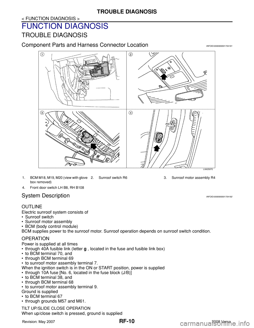
Component Parts and Harness Connector LocationINFOID:0000000001704191
System DescriptionINFOID:0000000001704192
OUTLINE
Electric sunroof system consists of
• Sunroof switch
• Sunroof motor assembly
• BCM (body control module)
BCM supplies power to the sunroof motor. Sunroof operation depends on sunroof switch condition.
OPERATION
Power is supplied at all times
• through 40A fusible link (letter g , located in the fuse and fusible link box)
• to BCM terminal 70, and
• through BCM terminal 69
• to sunroof motor assembly terminal 7.
When the ignition switch is in the ON or START position, power is supplied
• through 10A fuse [No. 6, located in the fuse block (J/B)]
• to BCM terminal 38, and
• through BCM terminal 68
• to sunroof motor assembly terminal 9.
Ground is supplied
• to BCM terminal 67
• through grounds M57 and M61.
TILT UP/SLIDE CLOSE OPERATION
When up/close switch is pressed, ground is supplied
LIIA2597E
1. BCM M18, M19, M20 (view with glove
box removed)2. Sunroof switch R6 3. Sunroof motor assembly R4
4. Front door switch LH B8, RH B108
Page 2541 of 2771
TROUBLE DIAGNOSIS
RF-11
< FUNCTION DIAGNOSIS >
C
D
E
F
G
H
J
K
L
MA
B
RF
N
O
P
• to sunroof motor assembly terminal 1
• through sunroof switch terminal 3
• through sunroof switch terminal 2
• through grounds M57 and M61.
Then the sunroof will tilt up/slide closed.
TILT DOWN/SLIDE OPEN OPERATION
When down/open switch is pressed, ground is supplied
• to sunroof motor assembly terminal 5
• through sunroof switch terminal 1
• through sunroof switch terminal 2
• through grounds M57 and M61.
Then the sunroof will tilt down/slide open.
AUTO OPERATION
The power sunroof AUTO feature makes it possible to slide open and slide closed or tilt up and tilt down the
sunroof without holding the sunroof switch in the UP/CLOSE or DOWN/OPEN position.
RETAINED POWER OPERATION
When the ignition switch is turned to OFF position from ON position, power is supplied for 45 seconds
• through BCM terminal 68
• to sunroof motor assembly terminal 9.
When power is supplied, the sunroof can be operated.
The retained power operation is canceled when the front door LH or RH is opened.
RAP signal period can be changed by CONSULT-III. Refer to RF-16, "
Work Support" .
ANTI-PINCH FUNCTION
The CPU (central processing unit) of sunroof motor assembly monitors the sunroof motor operation and the
sunroof position (fully-closed or other) by the signals from sunroof motor.
When sunroof motor detects an interruption during the following slide close and tilt down operation, sunroof
switch controls the motor for open and the sunroof will operate until it reaches full up position (during tilt down
operation) or 125 mm (4.92 in) or more in an open direction (during slide close operation).
• close operation and tilt down when ignition switch is in the ON position.
• close operation and tilt down during retained power operation.
INITIALIZATION FAILURE CONDITIONS
Initialization and teaching of system should be conducted if the following conditions exist:
• sunroof will only move in the UP/CLOSE direction, having a step by step motion
• sunroof does not have any auto operation.
INITIALIZATION PROCEDURE
If the sunroof does not close or open automatically, use the following procedure to return sunroof operation to
normal.
1. Press the switch to the UP/CLOSE position to tilt the sunroof up fully. When the sunroof reaches the full tilt
up position it will back up a few millimeters and stop.
2. Release the UP/CLOSE switch.
3. Within 5 seconds of releasing the UP/CLOSE switch, press and hold the UP/CLOSE switch again. The
sunroof will move to the full open position and back to the closed position.
NOTE:
If the UP/CLOSE switch is released anytime during this teaching process, all learned profile data will be dis-
carded and the procedure will have to be started over.
4. Release the UP/CLOSE switch. Do not disconnect power for at least two seconds. The sunroof is now ini-
tialized and taught.
Initializing procedure is complete. Confirm proper operation of the sunroof (slide open, slide closed, tilt up, tilt
down).
RE-TEACHING CONDITIONS
Re-teaching of system should be conducted if any of the following conditions exist:
• the sunroof is manually operated using the sunroof wrench with the battery discharged or disconnected.
• the sunroof is manually operated using the sunroof wrench with the key switch in the OFF position and
retained power timed out (after approximately 45 seconds or with a front door open).
• the sunroof motor assembly is replaced with a new one.
• the sunroof motor is removed from the sunroof assembly and operated before it is reinstalled.
Page 2542 of 2771
RF-12
< FUNCTION DIAGNOSIS >
TROUBLE DIAGNOSIS
• the sunroof motor is removed from the sunroof assembly and the glass panel position is changed.
RE-TEACHING PROCEDURE
1. Using the UP/CLOSE switch, move the sunroof toward the tilt position until it stops.
2. Release the UP/CLOSE switch.
3. Press the UP/CLOSE switch again and continuously hold. The sunroof will begin to move in about 10 sec-
onds.
4. Continue to hold the UP/CLOSE switch while the sunroof moves in a jogging motion to the full tilt position.
When the sunroof reaches the full tilt position, it will back up a few millimeters and stop.
5. Release the UP/CLOSE switch.
6. Within 5 seconds of releasing the UP/CLOSE switch, press and hold the UP/CLOSE switch again. The
sunroof will move to the full open position and back to the closed position.
NOTE:
If the UP/CLOSE switch is released anytime during this teaching process, all learned profile data will be dis-
carded and the procedure will have to be started over.
7. Release the UP/CLOSE switch. Do not disconnect power for at least two seconds. The sunroof is now re-
taught.
CAN Communication System DescriptionINFOID:0000000001704193
Refer to LAN-6 .
Page 2545 of 2771
TROUBLE DIAGNOSIS
RF-15
< FUNCTION DIAGNOSIS >
C
D
E
F
G
H
J
K
L
MA
B
RF
N
O
P
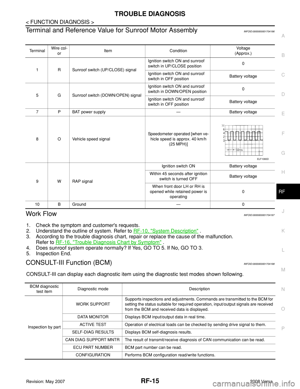
Terminal and Reference Value for Sunroof Motor AssemblyINFOID:0000000001704196
Work FlowINFOID:0000000001704197
1. Check the symptom and customer's requests.
2. Understand the outline of system. Refer to RF-10, "
System Description" .
3. According to the trouble diagnosis chart, repair or replace the cause of the malfunction.
Refer to RF-16, "
Trouble Diagnosis Chart by Symptom" .
4. Does sunroof system operate normally? If Yes, GO TO 5. If No, GO TO 3.
5. Inspection End.
CONSULT-III Function (BCM)INFOID:0000000001704198
CONSULT-III can display each diagnostic item using the diagnostic test modes shown following.
Te r m i n a lWire col-
orItem ConditionVoltag e
(Approx.)
1 R Sunroof switch (UP/CLOSE) signalIgnition switch ON and sunroof
switch in UP/CLOSE position0
Ignition switch ON and sunroof
switch in OFF positionBattery voltage
5 G Sunroof switch (DOWN/OPEN) signalIgnition switch ON and sunroof
switch in DOWN/OPEN position0
Ignition switch ON and sunroof
switch in OFF positionBattery voltage
7PBAT power supply — Battery voltage
8 O Vehicle speed signalSpeedometer operated [when ve-
hicle speed is approx. 40 km/h
(25 MPH)]
9 W RAP signalIgnition switch ON Battery voltage
Within 45 seconds after ignition
switch is turned OFFBattery voltage
When front door LH or RH is
opened while retained power is
operating0
10 B Ground — 0
ELF1080D
BCM diagnostic
test itemDiagnostic mode Description
Inspection by partWORK SUPPORTSupports inspections and adjustments. Commands are transmitted to the BCM for
setting the status suitable for required operation, input/output signals are received
from the BCM and received data is displayed.
DATA MONITOR Displays BCM input/output data in real time.
ACTIVE TEST Operation of electrical loads can be checked by sending drive signal to them.
SELF-DIAG RESULTS Displays BCM self-diagnosis results.
CAN DIAG SUPPORT MNTR The result of transmit/receive diagnosis of CAN communication can be read.
ECU PART NUMBER BCM part number can be read.
CONFIGURATION Performs BCM configuration read/write functions.
Page 2546 of 2771
RF-16
< FUNCTION DIAGNOSIS >
TROUBLE DIAGNOSIS
Work Support
INFOID:0000000001704199
Active TestINFOID:0000000001704200
Data MonitorINFOID:0000000001704201
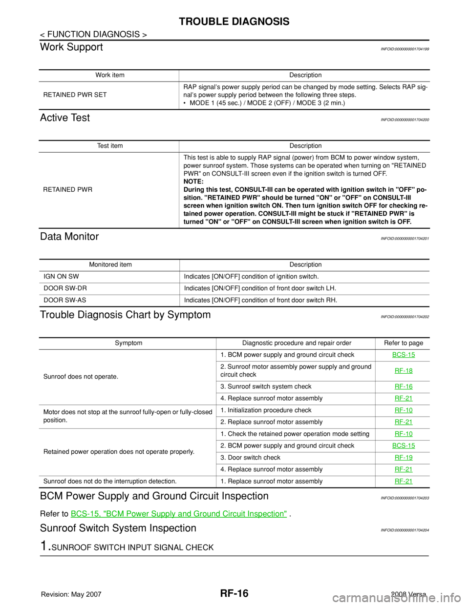
Trouble Diagnosis Chart by SymptomINFOID:0000000001704202
BCM Power Supply and Ground Circuit InspectionINFOID:0000000001704203
Refer to BCS-15, "BCM Power Supply and Ground Circuit Inspection" .
Sunroof Switch System InspectionINFOID:0000000001704204
1.SUNROOF SWITCH INPUT SIGNAL CHECK
Work item Description
RETAINED PWR SETRAP signal’s power supply period can be changed by mode setting. Selects RAP sig-
nal’s power supply period between the following three steps.
• MODE 1 (45 sec.) / MODE 2 (OFF) / MODE 3 (2 min.)
Test item Description
RETAINED PWRThis test is able to supply RAP signal (power) from BCM to power window system,
power sunroof system. Those systems can be operated when turning on "RETAINED
PWR" on CONSULT-III screen even if the ignition switch is turned OFF.
NOTE:
During this test, CONSULT-III can be operated with ignition switch in "OFF" po-
sition. "RETAINED PWR" should be turned "ON" or "OFF" on CONSULT-III
screen when ignition switch ON. Then turn ignition switch OFF for checking re-
tained power operation. CONSULT-III might be stuck if "RETAINED PWR" is
turned "ON" or "OFF" on CONSULT-III screen when ignition switch is OFF.
Monitored item Description
IGN ON SW Indicates [ON/OFF] condition of ignition switch.
DOOR SW-DR Indicates [ON/OFF] condition of front door switch LH.
DOOR SW-AS Indicates [ON/OFF] condition of front door switch RH.
Symptom Diagnostic procedure and repair order Refer to page
Sunroof does not operate.1. BCM power supply and ground circuit checkBCS-15
2. Sunroof motor assembly power supply and ground
circuit checkRF-18
3. Sunroof switch system checkRF-16
4. Replace sunroof motor assemblyRF-21
Motor does not stop at the sunroof fully-open or fully-closed
position.1. Initialization procedure checkRF-10
2. Replace sunroof motor assemblyRF-21
Retained power operation does not operate properly.1. Check the retained power operation mode settingRF-102. BCM power supply and ground circuit checkBCS-15
3. Door switch checkRF-19
4. Replace sunroof motor assemblyRF-21
Sunroof does not do the interruption detection. 1. Replace sunroof motor assemblyRF-21
Page 2547 of 2771
TROUBLE DIAGNOSIS
RF-17
< FUNCTION DIAGNOSIS >
C
D
E
F
G
H
J
K
L
MA
B
RF
N
O
P
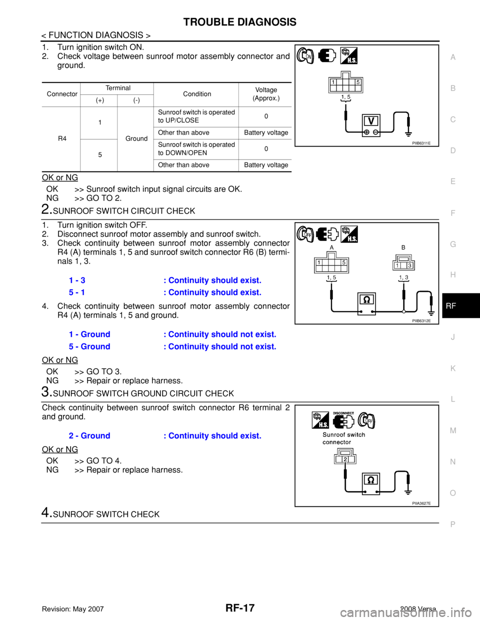
1. Turn ignition switch ON.
2. Check voltage between sunroof motor assembly connector and
ground.
OK or NG
OK >> Sunroof switch input signal circuits are OK.
NG >> GO TO 2.
2.SUNROOF SWITCH CIRCUIT CHECK
1. Turn ignition switch OFF.
2. Disconnect sunroof motor assembly and sunroof switch.
3. Check continuity between sunroof motor assembly connector
R4 (A) terminals 1, 5 and sunroof switch connector R6 (B) termi-
nals 1, 3.
4. Check continuity between sunroof motor assembly connector
R4 (A) terminals 1, 5 and ground.
OK or NG
OK >> GO TO 3.
NG >> Repair or replace harness.
3.SUNROOF SWITCH GROUND CIRCUIT CHECK
Check continuity between sunroof switch connector R6 terminal 2
and ground.
OK or NG
OK >> GO TO 4.
NG >> Repair or replace harness.
4.SUNROOF SWITCH CHECK
ConnectorTe r m i n a l
ConditionVo l ta g e
(Approx.)
(+) (-)
R41
GroundSunroof switch is operated
to UP/CLOSE0
Other than above Battery voltage
5Sunroof switch is operated
to DOWN/OPEN0
Other than above Battery voltage
PIIB6311E
1 - 3 : Continuity should exist.
5 - 1 : Continuity should exist.
1 - Ground : Continuity should not exist.
5 - Ground : Continuity should not exist.
PIIB6312E
2 - Ground : Continuity should exist.
PIIA3627E