Page 218 of 2771

AT-206
< SERVICE INFORMATION >
SHIFT CONTROL SYSTEM
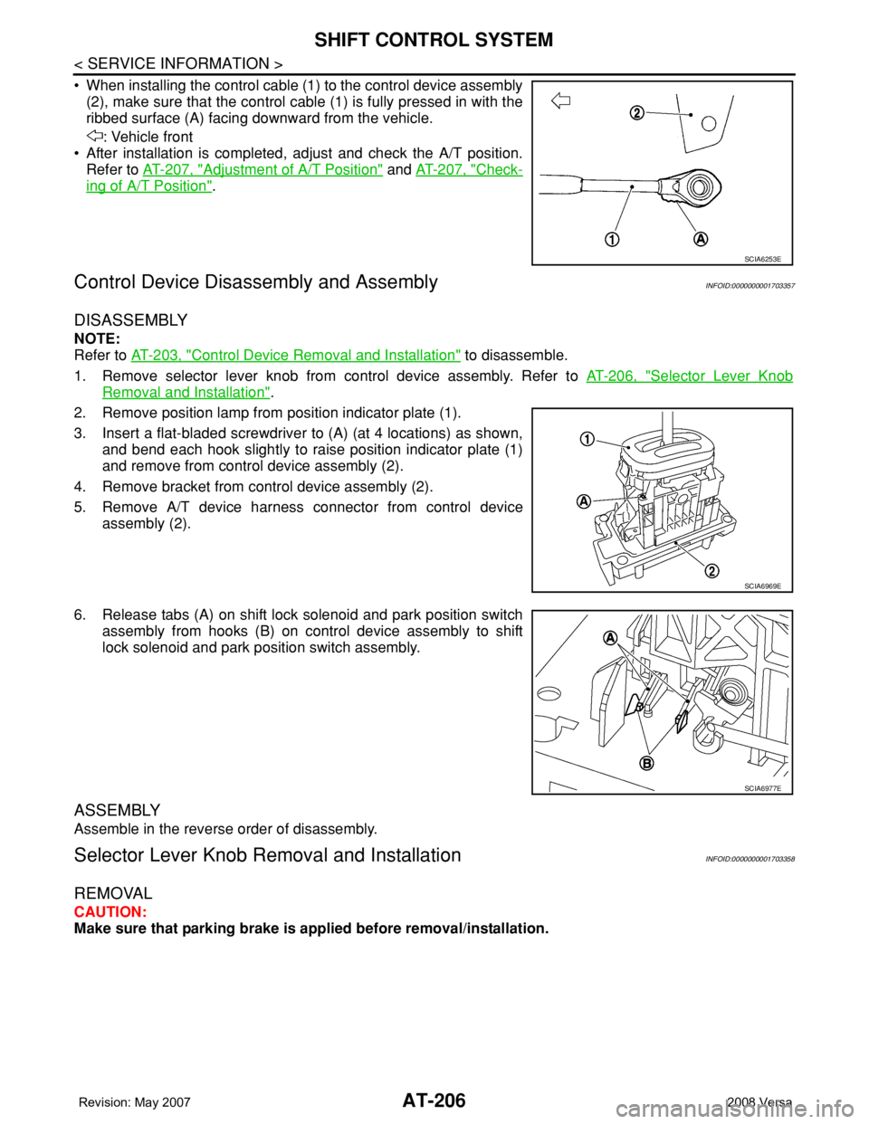
• When installing the control cable (1) to the control device assembly
(2), make sure that the control cable (1) is fully pressed in with the
ribbed surface (A) facing downward from the vehicle.
: Vehicle front
• After installation is completed, adjust and check the A/T position.
Refer to AT-207, "
Adjustment of A/T Position" and AT-207, "Check-
ing of A/T Position".
Control Device Disassembly and AssemblyINFOID:0000000001703357
DISASSEMBLY
NOTE:
Refer to AT-203, "
Control Device Removal and Installation" to disassemble.
1. Remove selector lever knob from control device assembly. Refer to AT-206, "
Selector Lever Knob
Removal and Installation".
2. Remove position lamp from position indicator plate (1).
3. Insert a flat-bladed screwdriver to (A) (at 4 locations) as shown,
and bend each hook slightly to raise position indicator plate (1)
and remove from control device assembly (2).
4. Remove bracket from control device assembly (2).
5. Remove A/T device harness connector from control device
assembly (2).
6. Release tabs (A) on shift lock solenoid and park position switch
assembly from hooks (B) on control device assembly to shift
lock solenoid and park position switch assembly.
ASSEMBLY
Assemble in the reverse order of disassembly.
Selector Lever Knob Removal and InstallationINFOID:0000000001703358
REMOVAL
CAUTION:
Make sure that parking brake is applied before removal/installation.
SCIA6253E
SCIA6969E
SCIA6977E
Page 219 of 2771

SHIFT CONTROL SYSTEM
AT-207
< SERVICE INFORMATION >
D
E
F
G
H
I
J
K
L
MA
B
AT
N
O
P
1. Place the selector lever knob (1) in “N” position.
2. Slide knob cover (2) downward.
3. Pull out lock pin (3) from selector lever knob (1).
4. Remove selector lever knob (1) and knob cover (2) as a set from
selector lever.
CAUTION:
Do not push selector button.
INSTALLATION
1. Insert lock pin (1) to selector lever knob (2).
2. Install knob cover (3) to selector lever knob (2).
3. Place the selector lever in “N” position.
4. Install selector lever knob over selector lever until a click is felt.
CAUTION:
• Do not tilt selector lever knob when installing. Install it
straight, and do not tap or apply any shock to install it.
• Do not push selector button.
Adjustment of A/T PositionINFOID:0000000001703359
Move selector lever from “P” position to “1” position. You should be able to feel the detents in each position. If
the detents cannot be felt or if the position indicator is improperly aligned, the control cable needs adjustment.
CAUTION:
Make sure that parking brake is applied before adjustment.
1. Remove the air duct assembly. Refer to EM-16
.
2. Remove the control cable nut (A) and control cable (1) and
place the manual lever (2) in the "P' position.
3. Place selector lever in “P” position.
4. Hold control cable (1) at the end and pull it with a force of 9.8 N
(approximately 1 kg, 2.2 lb). Release the control cable and tem-
porarily tighten control cable nut (A).
5. Tighten control cable nut (A) to the specified torque.
CAUTION:
Secure manual lever when tightening nut.
6. Move selector lever from “P” to “1” position again. Make sure that selector lever moves smoothly.
7. Check A/T position. Refer to AT-207, "
Checking of A/T Position".
8. Install air duct assembly. Refer to EM-16
.
Checking of A/T PositionINFOID:0000000001703360
1. Place selector lever in “P” position, and turn ignition switch ON (Do not start engine).
2. Make sure selector lever can be shifted to other than “P” position when brake pedal is depressed. Also
make sure selector lever can be shifted from “P” position only when brake pedal is depressed.
3. Move selector lever and check for excessive effort, sticking, noise or rattle.
4. Confirm selector lever stops at each position with the feel of engagement when it is moved through all the
positions. Check whether or not the actual position selector lever is in matches the position shown by the
shift position indicator and the transaxle.
SCIA6971E
SCIA6972E
Control cable nut : Refer to AT-203, "Control De-
vice Removal and Installation".WCIA0635E
Page 221 of 2771
A/T SHIFT LOCK SYSTEM
AT-209
< SERVICE INFORMATION >
D
E
F
G
H
I
J
K
L
MA
B
AT
N
O
P
A/T SHIFT LOCK SYSTEM
DescriptionINFOID:0000000001703361
• The mechanical key interlock mechanism also operates as a shift lock:
With the ignition switch turned to ON, selector lever cannot be shifted from “P” position to any other position
unless brake pedal is depressed.
With the key removed, selector lever cannot be shifted from “P” position to any other position.
The key cannot be removed unless selector lever is placed in “P” position.
• The shift lock and key interlock mechanisms are controlled by the ON-OFF operation of the shift lock sole-
noid and by the operation of the rotator and slider located inside key cylinder, respectively.
Shift Lock System Parts LocationINFOID:0000000001703362
1. Key interlock cable 2. Key cylinder 3. Stop lamp switch
4. Brake pedal 5. Shift lock release button 6. Key interlock cable
7. Shift lock solenoid 8. Park position switch
BCIA0038E
Page 222 of 2771
AT-210
< SERVICE INFORMATION >
A/T SHIFT LOCK SYSTEM
Wiring Diagram - AT - SHIFT
INFOID:0000000001703363
Diagnosis ProcedureINFOID:0000000001703364
SYMPTOM 1:
•Selector lever cannot be moved from “P” position with ignition switch in ON position and brake
pedal depressed.
BCWA0666E
Page 223 of 2771

A/T SHIFT LOCK SYSTEM
AT-211
< SERVICE INFORMATION >
D
E
F
G
H
I
J
K
L
MA
B
AT
N
O
P
•Selector lever can be moved from “P” position with ignition key in ON position and brake pedal
released.
•Selector lever can be moved from “P” position when ignition switch is removed from key cylinder.
SYMPTOM 2:
•Ignition key cannot be removed when selector lever is set to “P” position.
•Ignition key can be removed when selector lever is set to any position except “P” position.
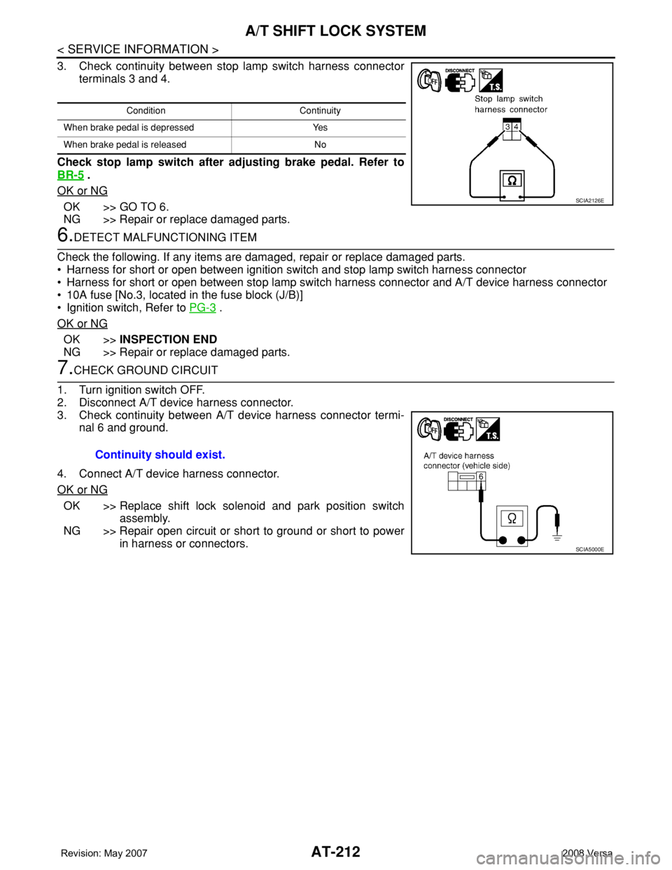
1.CHECK KEY INTERLOCK CABLE
Check key interlock cable for damage.
OK or NG
OK >> GO TO 2.
NG >> Repair key interlock cable. Refer to AT-213, "
Removal and Installation" .
2.CHECK A/T POSITION
Check A/T position. Refer to AT-207, "
Checking of A/T Position" .
OK or NG
OK >> GO TO 3.
NG >> Adjust control cable. Refer to AT-207, "
Adjustment of A/T Position" .
3.CHECK SHIFT LOCK SOLENOID AND PARK POSITION SWITCH
1. Turn ignition switch ON. (Do not start engine.)
2. Selector lever is set in “P” position.
3. Check operation sound.
OK or NG
OK >>INSPECTION END
NG >> GO TO 4.
4.CHECK POWER SOURCE
1. Turn ignition switch ON. (Do not start engine.)
2. Check voltage between A/T device harness connector terminal
5 and ground.
OK or NG
OK >> GO TO 7.
NG >> GO TO 5.
5.CHECK STOP LAMP SWITCH
1. Turn ignition switch OFF.
2. Disconnect stop lamp switch harness connector.
Condition Brake pedal Operation sound
When ignition switch is turned to ON position and selector lever is set in
“P” position.Depressed Yes
Released No
Voltage:
Brake pedal depressed: Battery voltage
Brake pedal released: 0V
SCIA7171E
Page 224 of 2771

AT-212
< SERVICE INFORMATION >
A/T SHIFT LOCK SYSTEM
3. Check continuity between stop lamp switch harness connector
terminals 3 and 4.
Check stop lamp switch after adjusting brake pedal. Refer to
BR-5
.
OK or NG
OK >> GO TO 6.
NG >> Repair or replace damaged parts.
6.DETECT MALFUNCTIONING ITEM
Check the following. If any items are damaged, repair or replace damaged parts.
• Harness for short or open between ignition switch and stop lamp switch harness connector
• Harness for short or open between stop lamp switch harness connector and A/T device harness connector
• 10A fuse [No.3, located in the fuse block (J/B)]
• Ignition switch, Refer to PG-3
.
OK or NG
OK >>INSPECTION END
NG >> Repair or replace damaged parts.
7.CHECK GROUND CIRCUIT
1. Turn ignition switch OFF.
2. Disconnect A/T device harness connector.
3. Check continuity between A/T device harness connector termi-
nal 6 and ground.
4. Connect A/T device harness connector.
OK or NG
OK >> Replace shift lock solenoid and park position switch
assembly.
NG >> Repair open circuit or short to ground or short to power
in harness or connectors.
Condition Continuity
When brake pedal is depressed Yes
When brake pedal is released No
SCIA2126E
Continuity should exist.
SCIA5000E
Page 226 of 2771

AT-214
< SERVICE INFORMATION >
KEY INTERLOCK CABLE
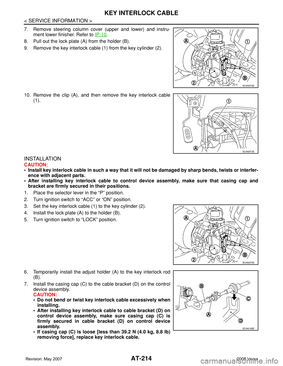
7. Remove steering column cover (upper and lower) and instru-
ment lower finisher. Refer to IP-10
.
8. Pull out the lock plate (A) from the holder (B).
9. Remove the key interlock cable (1) from the key cylinder (2).
10. Remove the clip (A), and then remove the key interlock cable
(1).
INSTALLATION
CAUTION:
• Install key interlock cable in such a way that it will not be damaged by sharp bends, twists or interfer-
ence with adjacent parts.
• After installing key interlock cable to control device assembly, make sure that casing cap and
bracket are firmly secured in their positions.
1. Place the selector lever in the “P” position.
2. Turn ignition switch to “ACC” or “ON” position.
3. Set the key interlock cable (1) to the key cylinder (2).
4. Install the lock plate (A) to the holder (B).
5. Turn ignition switch to “LOCK” position.
6. Temporarily install the adjust holder (A) to the key interlock rod
(B).
7. Install the casing cap (C) to the cable bracket (D) on the control
device assembly.
CAUTION:
• Do not bend or twist key interlock cable excessively when
installing.
• After installing key interlock cable to cable bracket (D) on
control device assembly, make sure casing cap (C) is
firmly secured in cable bracket (D) on control device
assembly.
• If casing cap (C) is loose [less than 39.2 N (4.0 kg, 8.8 lb)
removing force], replace key interlock cable.
SCIA6976E
SCIA6973E
SCIA6976E
SCIA6188E
Page 231 of 2771

ON-VEHICLE SERVICE
AT-219
< SERVICE INFORMATION >
D
E
F
G
H
I
J
K
L
MA
B
AT
N
O
P
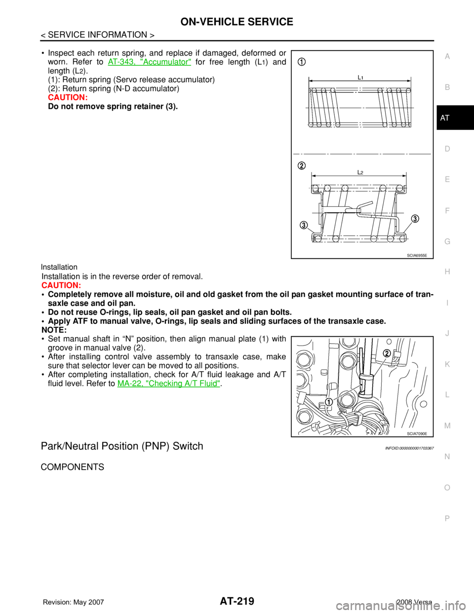
• Inspect each return spring, and replace if damaged, deformed or
worn. Refer to AT-343, "
Accumulator" for free length (L1) and
length (L
2).
(1): Return spring (Servo release accumulator)
(2): Return spring (N-D accumulator)
CAUTION:
Do not remove spring retainer (3).
Installation
Installation is in the reverse order of removal.
CAUTION:
• Completely remove all moisture, oil and old gasket from the oil pan gasket mounting surface of tran-
saxle case and oil pan.
• Do not reuse O-rings, lip seals, oil pan gasket and oil pan bolts.
• Apply ATF to manual valve, O-rings, lip seals and sliding surfaces of the transaxle case.
NOTE:
• Set manual shaft in “N” position, then align manual plate (1) with
groove in manual valve (2).
• After installing control valve assembly to transaxle case, make
sure that selector lever can be moved to all positions.
• After completing installation, check for A/T fluid leakage and A/T
fluid level. Refer to MA-22, "
Checking A/T Fluid".
Park/Neutral Position (PNP) SwitchINFOID:0000000001703367
COMPONENTS
SCIA6955E
SCIA7090E