2008 NISSAN TIIDA PN switch
[x] Cancel search: PN switchPage 232 of 2771
AT-220
< SERVICE INFORMATION >
ON-VEHICLE SERVICE
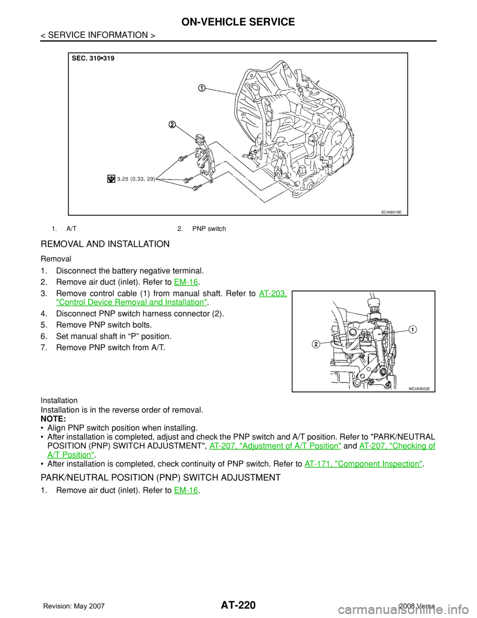
REMOVAL AND INSTALLATION
Removal
1. Disconnect the battery negative terminal.
2. Remove air duct (inlet). Refer to EM-16
.
3. Remove control cable (1) from manual shaft. Refer to AT-203,
"Control Device Removal and Installation".
4. Disconnect PNP switch harness connector (2).
5. Remove PNP switch bolts.
6. Set manual shaft in “P” position.
7. Remove PNP switch from A/T.
Installation
Installation is in the reverse order of removal.
NOTE:
• Align PNP switch position when installing.
• After installation is completed, adjust and check the PNP switch and A/T position. Refer to "PARK/NEUTRAL
POSITION (PNP) SWITCH ADJUSTMENT", AT-207, "
Adjustment of A/T Position" and AT-207, "Checking of
A/T Position".
• After installation is completed, check continuity of PNP switch. Refer to AT-171, "
Component Inspection".
PARK/NEUTRAL POSITION (PNP) SWITCH ADJUSTMENT
1. Remove air duct (inlet). Refer to EM-16.
1. A/T 2. PNP switch
SCIA8018E
WCIA0653E
Page 233 of 2771
ON-VEHICLE SERVICE
AT-221
< SERVICE INFORMATION >
D
E
F
G
H
I
J
K
L
MA
B
AT
N
O
P
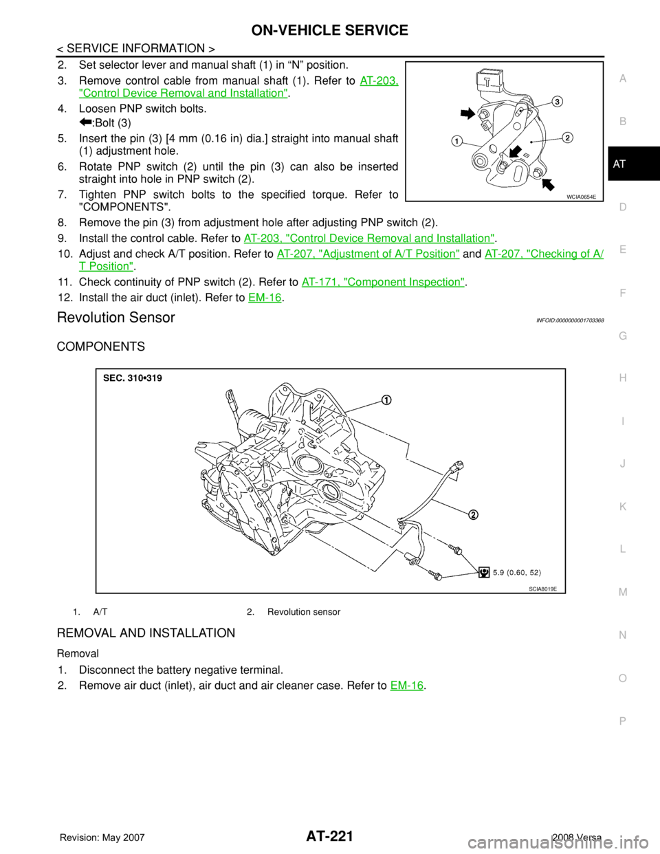
2. Set selector lever and manual shaft (1) in “N” position.
3. Remove control cable from manual shaft (1). Refer to AT-203,
"Control Device Removal and Installation".
4. Loosen PNP switch bolts.
:Bolt (3)
5. Insert the pin (3) [4 mm (0.16 in) dia.] straight into manual shaft
(1) adjustment hole.
6. Rotate PNP switch (2) until the pin (3) can also be inserted
straight into hole in PNP switch (2).
7. Tighten PNP switch bolts to the specified torque. Refer to
"COMPONENTS".
8. Remove the pin (3) from adjustment hole after adjusting PNP switch (2).
9. Install the control cable. Refer to AT-203, "
Control Device Removal and Installation".
10. Adjust and check A/T position. Refer to AT-207, "
Adjustment of A/T Position" and AT-207, "Checking of A/
T Position".
11. Check continuity of PNP switch (2). Refer to AT-171, "
Component Inspection".
12. Install the air duct (inlet). Refer to EM-16
.
Revolution SensorINFOID:0000000001703368
COMPONENTS
REMOVAL AND INSTALLATION
Removal
1. Disconnect the battery negative terminal.
2. Remove air duct (inlet), air duct and air cleaner case. Refer to EM-16
.
WCIA0654E
1. A/T 2. Revolution sensor
SCIA8019E
Page 239 of 2771
TRANSAXLE ASSEMBLY
AT-227
< SERVICE INFORMATION >
D
E
F
G
H
I
J
K
L
MA
B
AT
N
O
P
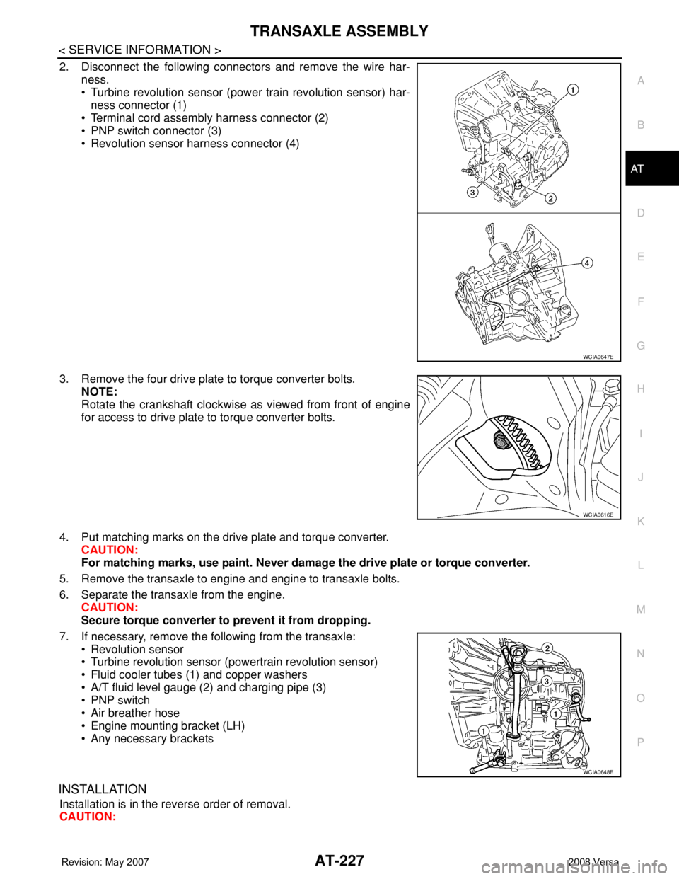
2. Disconnect the following connectors and remove the wire har-
ness.
• Turbine revolution sensor (power train revolution sensor) har-
ness connector (1)
• Terminal cord assembly harness connector (2)
• PNP switch connector (3)
• Revolution sensor harness connector (4)
3. Remove the four drive plate to torque converter bolts.
NOTE:
Rotate the crankshaft clockwise as viewed from front of engine
for access to drive plate to torque converter bolts.
4. Put matching marks on the drive plate and torque converter.
CAUTION:
For matching marks, use paint. Never damage the drive plate or torque converter.
5. Remove the transaxle to engine and engine to transaxle bolts.
6. Separate the transaxle from the engine.
CAUTION:
Secure torque converter to prevent it from dropping.
7. If necessary, remove the following from the transaxle:
• Revolution sensor
• Turbine revolution sensor (powertrain revolution sensor)
• Fluid cooler tubes (1) and copper washers
• A/T fluid level gauge (2) and charging pipe (3)
• PNP switch
• Air breather hose
• Engine mounting bracket (LH)
• Any necessary brackets
INSTALLATION
Installation is in the reverse order of removal.
CAUTION:
WCIA0647E
WCIA0616E
WCIA0648E
Page 248 of 2771
AT-236
< SERVICE INFORMATION >
OVERHAUL
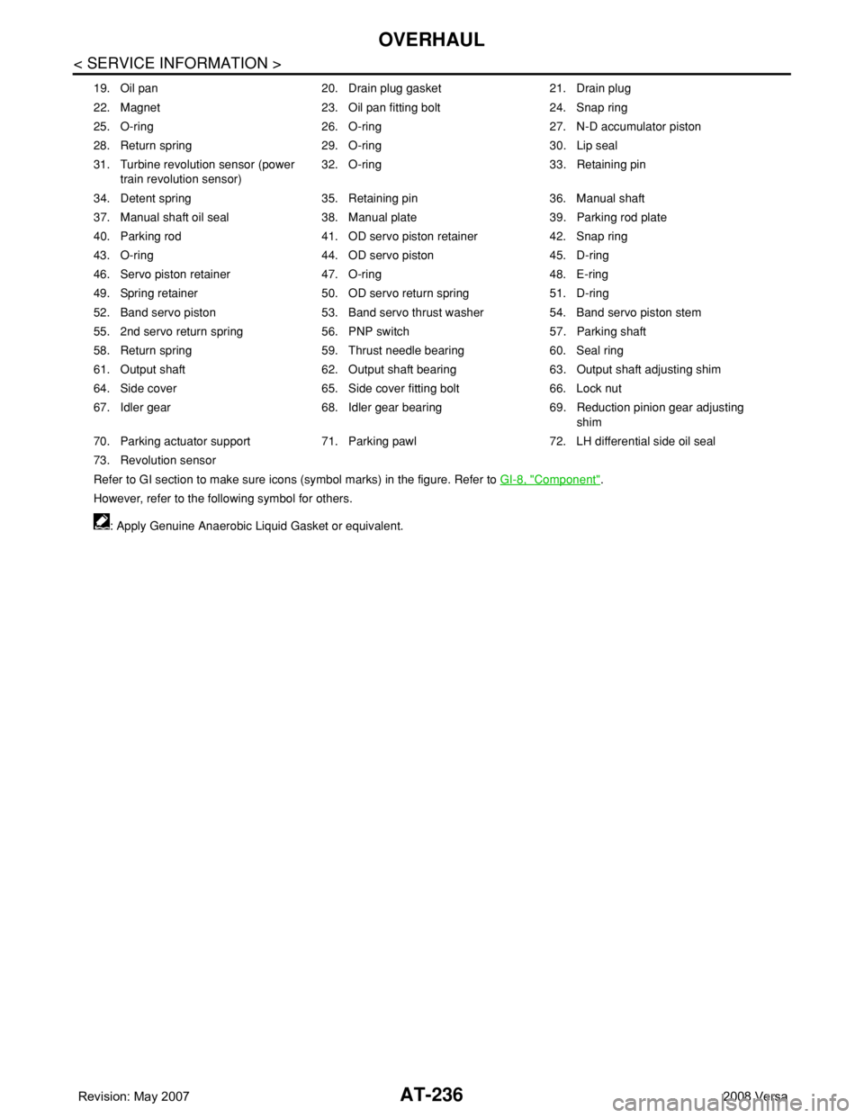
19. Oil pan 20. Drain plug gasket 21. Drain plug
22. Magnet 23. Oil pan fitting bolt 24. Snap ring
25. O-ring 26. O-ring 27. N-D accumulator piston
28. Return spring 29. O-ring 30. Lip seal
31. Turbine revolution sensor (power
train revolution sensor)32. O-ring 33. Retaining pin
34. Detent spring 35. Retaining pin 36. Manual shaft
37. Manual shaft oil seal 38. Manual plate 39. Parking rod plate
40. Parking rod 41. OD servo piston retainer 42. Snap ring
43. O-ring 44. OD servo piston 45. D-ring
46. Servo piston retainer 47. O-ring 48. E-ring
49. Spring retainer 50. OD servo return spring 51. D-ring
52. Band servo piston 53. Band servo thrust washer 54. Band servo piston stem
55. 2nd servo return spring 56. PNP switch 57. Parking shaft
58. Return spring 59. Thrust needle bearing 60. Seal ring
61. Output shaft 62. Output shaft bearing 63. Output shaft adjusting shim
64. Side cover 65. Side cover fitting bolt 66. Lock nut
67. Idler gear 68. Idler gear bearing 69. Reduction pinion gear adjusting
shim
70. Parking actuator support 71. Parking pawl 72. LH differential side oil seal
73. Revolution sensor
Refer to GI section to make sure icons (symbol marks) in the figure. Refer to GI-8, "
Component".
However, refer to the following symbol for others.
: Apply Genuine Anaerobic Liquid Gasket or equivalent.
Page 254 of 2771
AT-242
< SERVICE INFORMATION >
DISASSEMBLY
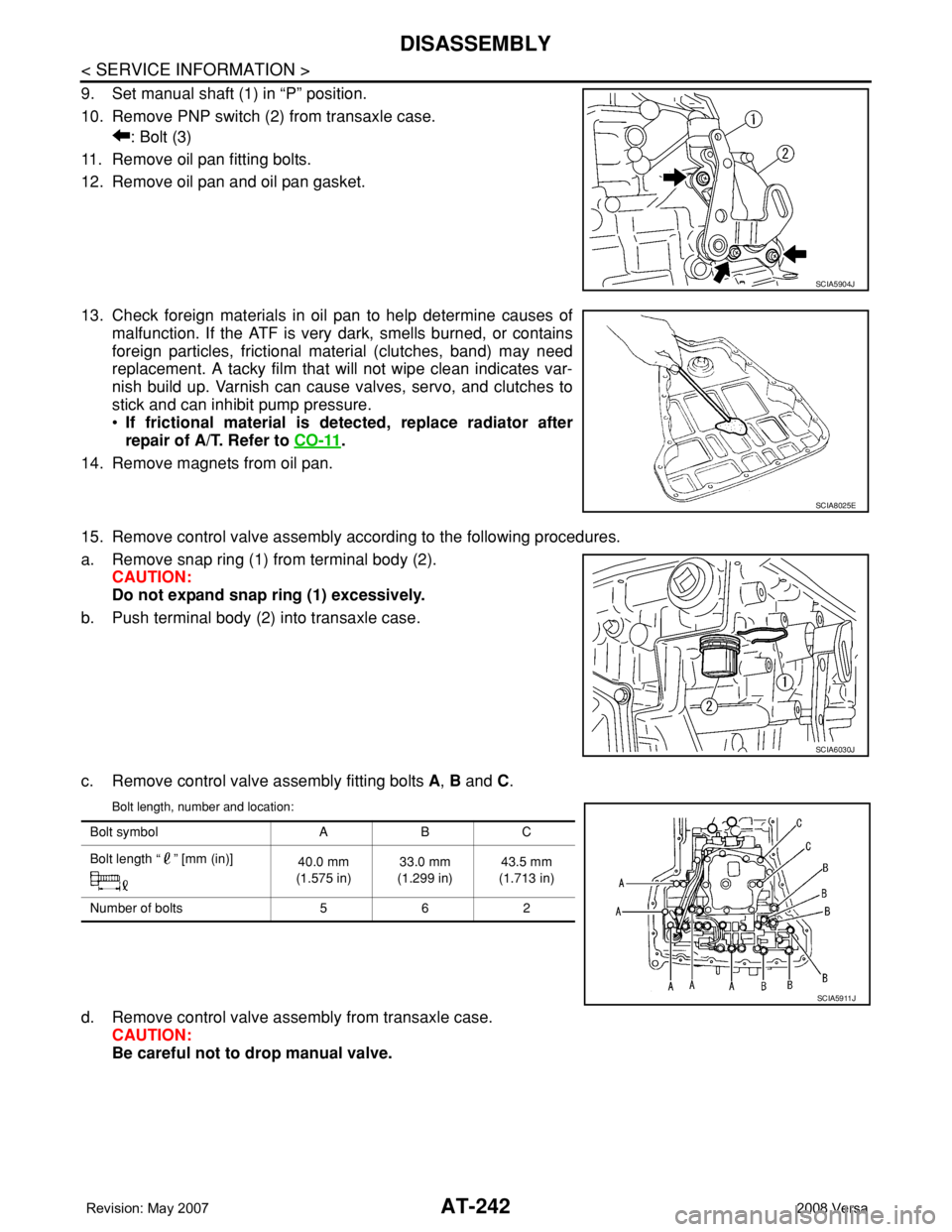
9. Set manual shaft (1) in “P” position.
10. Remove PNP switch (2) from transaxle case.
: Bolt (3)
11. Remove oil pan fitting bolts.
12. Remove oil pan and oil pan gasket.
13. Check foreign materials in oil pan to help determine causes of
malfunction. If the ATF is very dark, smells burned, or contains
foreign particles, frictional material (clutches, band) may need
replacement. A tacky film that will not wipe clean indicates var-
nish build up. Varnish can cause valves, servo, and clutches to
stick and can inhibit pump pressure.
•If frictional material is detected, replace radiator after
repair of A/T. Refer to CO-11
.
14. Remove magnets from oil pan.
15. Remove control valve assembly according to the following procedures.
a. Remove snap ring (1) from terminal body (2).
CAUTION:
Do not expand snap ring (1) excessively.
b. Push terminal body (2) into transaxle case.
c. Remove control valve assembly fitting bolts A, B and C.
Bolt length, number and location:
d. Remove control valve assembly from transaxle case.
CAUTION:
Be careful not to drop manual valve.
SCIA5904J
SCIA8025E
SCIA6030J
Bolt symbol A B C
Bolt length “ ” [mm (in)]
40.0 mm
(1.575 in)33.0 mm
(1.299 in)43.5 mm
(1.713 in)
Number of bolts 5 6 2
SCIA5911J
Page 351 of 2771
ASSEMBLY
AT-339
< SERVICE INFORMATION >
D
E
F
G
H
I
J
K
L
MA
B
AT
N
O
P
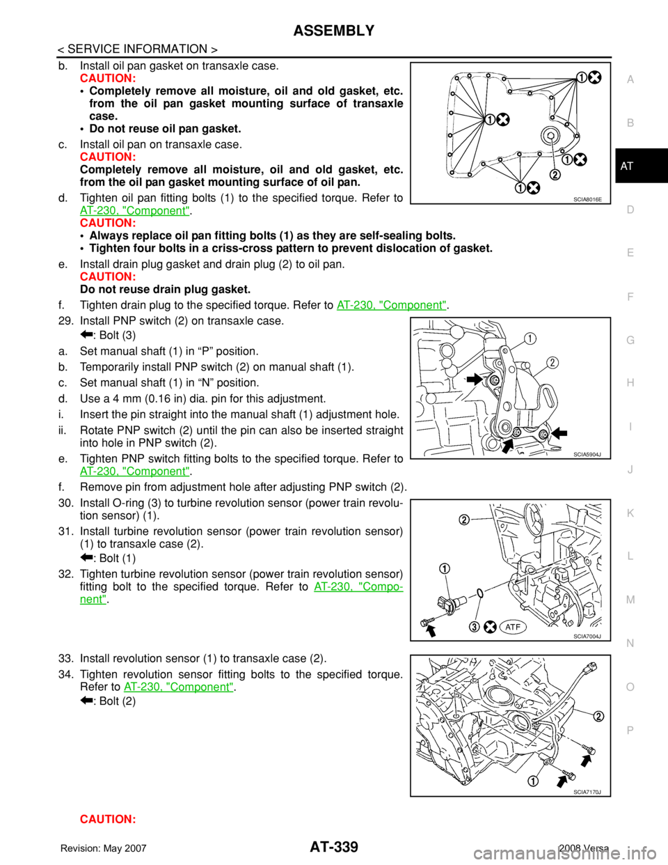
b. Install oil pan gasket on transaxle case.
CAUTION:
• Completely remove all moisture, oil and old gasket, etc.
from the oil pan gasket mounting surface of transaxle
case.
• Do not reuse oil pan gasket.
c. Install oil pan on transaxle case.
CAUTION:
Completely remove all moisture, oil and old gasket, etc.
from the oil pan gasket mounting surface of oil pan.
d. Tighten oil pan fitting bolts (1) to the specified torque. Refer to
AT-230, "
Component".
CAUTION:
• Always replace oil pan fitting bolts (1) as they are self-sealing bolts.
• Tighten four bolts in a criss-cross pattern to prevent dislocation of gasket.
e. Install drain plug gasket and drain plug (2) to oil pan.
CAUTION:
Do not reuse drain plug gasket.
f. Tighten drain plug to the specified torque. Refer to AT-230, "
Component".
29. Install PNP switch (2) on transaxle case.
: Bolt (3)
a. Set manual shaft (1) in “P” position.
b. Temporarily install PNP switch (2) on manual shaft (1).
c. Set manual shaft (1) in “N” position.
d. Use a 4 mm (0.16 in) dia. pin for this adjustment.
i. Insert the pin straight into the manual shaft (1) adjustment hole.
ii. Rotate PNP switch (2) until the pin can also be inserted straight
into hole in PNP switch (2).
e. Tighten PNP switch fitting bolts to the specified torque. Refer to
AT-230, "
Component".
f. Remove pin from adjustment hole after adjusting PNP switch (2).
30. Install O-ring (3) to turbine revolution sensor (power train revolu-
tion sensor) (1).
31. Install turbine revolution sensor (power train revolution sensor)
(1) to transaxle case (2).
: Bolt (1)
32. Tighten turbine revolution sensor (power train revolution sensor)
fitting bolt to the specified torque. Refer to AT-230, "
Compo-
nent".
33. Install revolution sensor (1) to transaxle case (2).
34. Tighten revolution sensor fitting bolts to the specified torque.
Refer to AT-230, "
Component".
: Bolt (2)
CAUTION:
SCIA8016E
SCIA5904J
SCIA7004J
SCIA7170J
Page 360 of 2771

AV-1
ELECTRICAL
C
D
E
F
G
H
I
J
L
M
SECTION AV
A
B
AV
N
O
P
CONTENTS
AUDIO, VISUAL, NAVIGATION & TELEPHONE SYS-
TEM
SERVICE INFORMATION ............................2
PRECAUTIONS ...................................................2
Precaution for Supplemental Restraint System
(SRS) "AIR BAG" and "SEAT BELT PRE-TEN-
SIONER" ...................................................................
2
PREPARATION ...................................................3
Commercial Service Tool ..........................................3
AUDIO .................................................................4
Component Parts Location ........................................4
System Description ...................................................4
Schematic .................................................................6
Wiring Diagram - AUDIO - .........................................8
Audio Unit (Base System) Harness Connector
Terminal Layout ......................................................
15
Terminal and Reference Value for Audio Unit
(Base System) .........................................................
15
Audio Unit (Mid Level and Premium System) Har-
ness Connector Terminal Layout ............................
16
Terminal and Reference Value for Audio Unit (Mid
Level and Premium System) ...................................
16
Subwoofer Harness Connector Terminal Layout
(Premium Audio System) ........................................
19
Terminal and Reference Value for Subwoofer
(Premium Audio System) ........................................
19
Satellite Radio Tuner Harness Connector Termi-
nal Layout ................................................................
19
Terminal and Reference Value for Satellite Radio
Tuner .......................................................................
20
Trouble Diagnosis ...................................................20
Noise Inspection ......................................................21
Power Supply Circuit Inspection .............................22
Satellite Radio Tuner (Factory Installed) Power
and Ground Supply Circuit Inspection .....................
23
Satellite Radio Tuner (Factory Installed) Commu-
nication Circuit Inspection .......................................
24
Satellite Radio Tuner (Factory Installed) Left
Channel Audio Signal Circuit Inspection .................
26
Satellite Radio Tuner (Factory Installed) Right
Channel Audio Signal Circuit Inspection .................
26
Steering Switch Check (With Bluetooth) ..................27
Sound Is Not Heard from Front Door Speaker
(Base System) .........................................................
29
Sound Is Not Heard from Rear Door Speaker
(Base System) .........................................................
30
Sound Is Not Heard from Front Door Speaker or
Tweeter (Mid Level and Premium System) .............
31
Sound Is Not Heard from Rear Door Speaker (Mid
Level and Premium System) ...................................
32
Sound Is Not Heard from Subwoofer (Premium
System) ...................................................................
34
Removal and Installation .........................................36
AUDIO ANTENNA .............................................41
Location of Antenna .................................................41
Removal and Installation of Roof Antenna ..............41
TELEPHONE .....................................................43
Component Parts and Harness Connector Loca-
tion ...........................................................................
43
System Description ..................................................43
Wiring Diagram - H/PHON - ....................................45
Bluetooth Control Unit Harness Connector Termi-
nal Layout ................................................................
47
Terminal and Reference Value for Bluetooth Con-
trol Unit ....................................................................
47
Bluetooth Control Unit Self-Diagnosis Function ......48
Workflow ..................................................................49
Power Supply and Ground Circuit Inspection for
Bluetooth Control Unit .............................................
49
Basic Inspection of Hands-Free Phone ...................50
Steering Wheel Audio Control Switch Does Not
Operate ....................................................................
51
Voice Activated Control Function Does Not Oper-
ate ............................................................................
52
Removal and Installation .........................................54
Page 361 of 2771
AV-2
< SERVICE INFORMATION >
PRECAUTIONS
SERVICE INFORMATION
PRECAUTIONS
Precaution for Supplemental Restraint System (SRS) "AIR BAG" and "SEAT BELT
PRE-TENSIONER"
INFOID:0000000001704647
The Supplemental Restraint System such as “AIR BAG” and “SEAT BELT PRE-TENSIONER”, used along
with a front seat belt, helps to reduce the risk or severity of injury to the driver and front passenger for certain
types of collision. This system includes seat belt switch inputs and dual stage front air bag modules. The SRS
system uses the seat belt switches to determine the front air bag deployment, and may only deploy one front
air bag, depending on the severity of a collision and whether the front occupants are belted or unbelted.
Information necessary to service the system safely is included in the SR and SB section of this Service Man-
ual.
WARNING:
• To avoid rendering the SRS inoperative, which could increase the risk of personal injury or death in
the event of a collision which would result in air bag inflation, all maintenance must be performed by
an authorized NISSAN/INFINITI dealer.
• Improper maintenance, including incorrect removal and installation of the SRS, can lead to personal
injury caused by unintentional activation of the system. For removal of Spiral Cable and Air Bag
Module, see the SR section.
• Do not use electrical test equipment on any circuit related to the SRS unless instructed to in this
Service Manual. SRS wiring harnesses can be identified by yellow and/or orange harnesses or har-
ness connectors.