2008 NISSAN TIIDA Engine Control System
[x] Cancel search: Engine Control SystemPage 1100 of 2771

EC-26
< SERVICE INFORMATION >
ENGINE CONTROL SYSTEM
If the engine speed is above 2,000 rpm under no load [for example, the shift lever position is P or N (A/T,
CVT), Neutral (M/T) and engine speed is over 2,000 rpm] fuel will be cut off after some time. The exact time
when the fuel is cut off varies based on engine speed.
Fuel cut will be operated until the engine speed reaches 1,500 rpm, then fuel cut will be cancelled.
NOTE:
This function is different from deceleration control listed under EC-22, "
Multiport Fuel Injection (MFI) System".
Page 1101 of 2771

AIR CONDITIONING CUT CONTROL
EC-27
< SERVICE INFORMATION >
C
D
E
F
G
H
I
J
K
L
MA
EC
N
P O
AIR CONDITIONING CUT CONTROL
Input/Output Signal ChartINFOID:0000000001702558
*1: This signal is sent to the ECM through CAN communication line.
*2: ECM determines the start signal status by the signals of engine speed and battery voltage.
System DescriptionINFOID:0000000001702559
This system improves engine operation when the air conditioner is used.
Under the following conditions, the air conditioner is turned off.
• When the accelerator pedal is fully depressed.
• When cranking the engine.
• At high engine speeds.
• When the engine coolant temperature becomes excessively high.
• When operating power steering during low engine speed or low vehicle speed.
• When engine speed is excessively low.
• When refrigerant pressure is excessively low or high.
Sensor Input Signal to ECM ECM function Actuator
Air conditioner switch
Air conditioner ON signal*
1
Air conditioner
cut controlAir conditioner relay Accelerator pedal position sensor Accelerator pedal position
Crankshaft position sensor (POS)
Camshaft position sensor (PHASE)Engine speed*
2
Engine coolant temperature sensor Engine coolant temperature
Battery
Battery voltage*
2
Refrigerant pressure sensor Refrigerant pressure
EPS control unit
Power steering operation*
1
Wheel sensor
Vehicle speed*1
Page 1102 of 2771

EC-28
< SERVICE INFORMATION >
AUTOMATIC SPEED CONTROL DEVICE (ASCD)
AUTOMATIC SPEED CONTROL DEVICE (ASCD)
System DescriptionINFOID:0000000001702560
INPUT/OUTPUT SIGNAL CHART
*: This signal is sent to the ECM through CAN communication line.
BASIC ASCD SYSTEM
Refer to Owner's Manual for ASCD operating instructions.
Automatic Speed Control Device (ASCD) allows a driver to keep vehicle at predetermined constant speed
without depressing accelerator pedal. Driver can set vehicle speed in advance between approximately 40 km/
h (25 MPH) and 144 km/h (89 MPH).
ECM controls throttle angle of electric throttle control actuator to regulate engine speed.
Operation status of ASCD is indicated by CRUISE indicator and SET indicator in combination meter. If any
malfunction occurs in ASCD system, it automatically deactivates control.
NOTE:
Always drive vehicle in safe manner according to traffic conditions and obey all traffic laws.
SET OPERATION
Press MAIN switch. (The CRUISE indicator in combination meter illuminates.)
When vehicle speed reaches a desired speed between approximately 40 km/h (25 MPH) and 144 km/h (89
MPH), press SET/COAST switch. (Then SET indicator in combination meter illuminates.)
ACCELERATE OPERATION
If the RESUME/ACCELERATE switch is depressed during cruise control driving, increase the vehicle speed
until the switch is released or vehicle speed reaches maximum speed controlled by the system.
And then ASCD will keep the new set speed.
CANCEL OPERATION
When any of following conditions exist, cruise operation will be canceled.
• CANCEL switch is pressed
• More than two switches at ASCD steering switch are pressed at the same time (Set speed will be cleared)
• Brake pedal is depressed
• Clutch pedal is depressed or gear position is changed to the neutral position (M/T models)
• Selector lever is changed to N, P, R position (A/T and CVT models)
• Vehicle speed decreased to 13 km/h (8 MPH) lower than the set speed
When the ECM detects any of the following conditions, the ECM will cancel the cruise operation and inform
the driver by blinking indicator lamp.
• Engine coolant temperature is slightly higher than the normal operating temperature, CRUISE lamp may
blink slowly.
When the engine coolant temperature decreases to the normal operating temperature, CRUISE lamp will
stop blinking and the cruise operation will be able to work by pressing SET/COAST switch or RESUME/
ACCELERATE switch.
• Malfunction for some self-diagnoses regarding ASCD control: SET lamp will blink quickly.
If MAIN switch is turned to OFF during ASCD is activated, all of ASCD operations will be canceled and vehicle
speed memory will be erased.
COAST OPERATION
When the SET/COAST switch is depressed during cruise control driving, decrease vehicle set speed until the
switch is released. And then ASCD will keep the new set speed.
Sensor Input signal to ECM ECM function Actuator
ASCD brake switch Brake pedal operation
ASCD vehicle speed controlElectric throttle control
actuator Stop lamp switch Brake pedal operation
ASCD clutch switch (M/T models) Clutch pedal operation
ASCD steering switch ASCD steering switch operation
Park/neutral position (PNP) switch Gear position
Combination meter Vehicle speed*
TCM (A/T and CVT models) Powertrain revolution*
Page 1105 of 2771

EVAPORATIVE EMISSION SYSTEM
EC-31
< SERVICE INFORMATION >
C
D
E
F
G
H
I
J
K
L
MA
EC
N
P O
EVAPORATIVE EMISSION SYSTEM
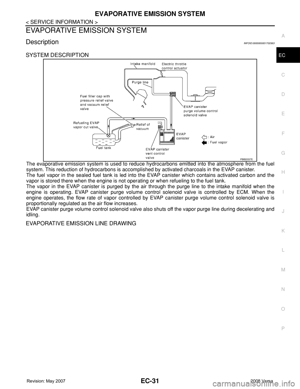
DescriptionINFOID:0000000001702563
SYSTEM DESCRIPTION
The evaporative emission system is used to reduce hydrocarbons emitted into the atmosphere from the fuel
system. This reduction of hydrocarbons is accomplished by activated charcoals in the EVAP canister.
The fuel vapor in the sealed fuel tank is led into the EVAP canister which contains activated carbon and the
vapor is stored there when the engine is not operating or when refueling to the fuel tank.
The vapor in the EVAP canister is purged by the air through the purge line to the intake manifold when the
engine is operating. EVAP canister purge volume control solenoid valve is controlled by ECM. When the
engine operates, the flow rate of vapor controlled by EVAP canister purge volume control solenoid valve is
proportionally regulated as the air flow increases.
EVAP canister purge volume control solenoid valve also shuts off the vapor purge line during decelerating and
idling.
EVAPORATIVE EMISSION LINE DRAWING
PBIB2037E
Page 1109 of 2771

EVAPORATIVE EMISSION SYSTEM
EC-35
< SERVICE INFORMATION >
C
D
E
F
G
H
I
J
K
L
MA
EC
N
P O
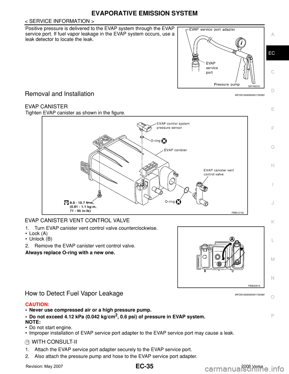
Positive pressure is delivered to the EVAP system through the EVAP
service port. If fuel vapor leakage in the EVAP system occurs, use a
leak detector to locate the leak.
Removal and InstallationINFOID:0000000001702565
EVAP CANISTER
Tighten EVAP canister as shown in the figure.
EVAP CANISTER VENT CONTROL VALVE
1. Turn EVAP canister vent control valve counterclockwise.
• Lock (A)
• Unlock (B)
2. Remove the EVAP canister vent control valve.
Always replace O-ring with a new one.
How to Detect Fuel Vapor LeakageINFOID:0000000001702566
CAUTION:
• Never use compressed air or a high pressure pump.
• Do not exceed 4.12 kPa (0.042 kg/cm
2, 0.6 psi) of pressure in EVAP system.
NOTE:
• Do not start engine.
• Improper installation of EVAP service port adapter to the EVAP service port may cause a leak.
WITH CONSULT-II
1. Attach the EVAP service port adapter securely to the EVAP service port.
2. Also attach the pressure pump and hose to the EVAP service port adapter.
SEF462UC
PBIB1214E
PBIB3091E
Page 1112 of 2771

EC-38
< SERVICE INFORMATION >
ON BOARD REFUELING VAPOR RECOVERY (ORVR)
ON BOARD REFUELING VAPOR RECOVERY (ORVR)
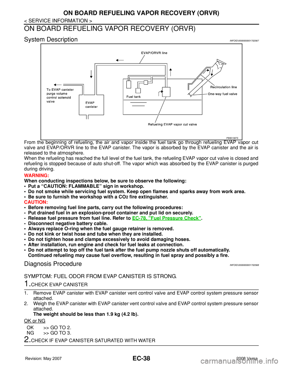
System DescriptionINFOID:0000000001702567
From the beginning of refueling, the air and vapor inside the fuel tank go through refueling EVAP vapor cut
valve and EVAP/ORVR line to the EVAP canister. The vapor is absorbed by the EVAP canister and the air is
released to the atmosphere.
When the refueling has reached the full level of the fuel tank, the refueling EVAP vapor cut valve is closed and
refueling is stopped because of auto shut-off. The vapor which was absorbed by the EVAP canister is purged
during driving.
WARNING:
When conducting inspections below, be sure to observe the following:
• Put a “CAUTION: FLAMMABLE” sign in workshop.
• Do not smoke while servicing fuel system. Keep open flames and sparks away from work area.
• Be sure to furnish the workshop with a CO
2 fire extinguisher.
CAUTION:
• Before removing fuel line parts, carry out the following procedures:
- Put drained fuel in an explosion-proof container and put lid on securely.
- Release fuel pressure from fuel line. Refer to EC-78, "
Fuel Pressure Check".
- Disconnect negative battery cable.
• Always replace O-ring when the fuel gauge retainer is removed.
• Do not kink or twist hose and tube when they are installed.
• Do not tighten hose and clamps excessively to avoid damaging hoses.
• After installation, run engine and check for fuel leaks at connection.
• Do not attempt to top off the fuel tank after the fuel pump nozzle shuts off automatically.
Continued refueling may cause fuel overflow, resulting in fuel spray and possibly a fire.
Diagnosis ProcedureINFOID:0000000001702568
SYMPTOM: FUEL ODOR FROM EVAP CANISTER IS STRONG.
1.CHECK EVAP CANISTER
1. Remove EVAP canister with EVAP canister vent control valve and EVAP control system pressure sensor
attached.
2. Weigh the EVAP canister with EVAP canister vent control valve and EVAP control system pressure sensor
attached.
The weight should be less than 1.9 kg (4.2 lb).
OK or NG
OK >> GO TO 2.
NG >> GO TO 3.
2.CHECK IF EVAP CANISTER SATURATED WITH WATER
PBIB1387E
Page 1120 of 2771

EC-46
< SERVICE INFORMATION >
ON BOARD DIAGNOSTIC (OBD) SYSTEM
ON BOARD DIAGNOSTIC (OBD) SYSTEM
IntroductionINFOID:0000000001702573
The ECM has an on board diagnostic system, which detects malfunctions related to engine sensors or actua-
tors. The ECM also records various emission-related diagnostic information including:
The above information can be checked using procedures listed in the table below.
×: Applicable —: Not applicable
*: When DTC and 1st trip DTC simultaneously appear on the display, they cannot be clearly distinguished from each other.
The malfunction indicator lamp (MIL) on the instrument panel lights up when the same malfunction is detected
in two consecutive trips (Two trip detection logic), or when the ECM enters fail-safe mode.
(Refer to EC-87, "
Fail-Safe Chart".)
Two Trip Detection LogicINFOID:0000000001702574
When a malfunction is detected for the first time, 1st trip DTC and 1st trip Freeze Frame data are stored in the
ECM memory. The MIL will not light up at this stage. <1st trip>
If the same malfunction is detected again during the next drive, the DTC and Freeze Frame data are stored in
the ECM memory, and the MIL lights up. The MIL lights up at the same time when the DTC is stored. <2nd
trip> The “trip” in the “Two Trip Detection Logic” means a driving mode in which self-diagnosis is performed
during vehicle operation. Specific on board diagnostic items will cause the ECM to light up or blink the MIL,
and store DTC and Freeze Frame data, even in the 1st trip, as shown below.
×: Applicable —: Not applicable
When there is an open circuit on MIL circuit, the ECM cannot warn the driver by MIL lighting up when there is
malfunction on engine control system.
Emission-related diagnostic information Diagnostic service
Diagnostic Trouble Code (DTC) Service $03 of SAE J1979
Freeze Frame data Service $02 of SAE J1979
System Readiness Test (SRT) code Service $01 of SAE J1979
1st Trip Diagnostic Trouble Code (1st Trip DTC) Service $07 of SAE J1979
1st Trip Freeze Frame data
Test values and Test limits Service $06 of SAE J1979
Calibration ID Service $09 of SAE J1979
DTC 1st trip DTCFreeze Frame
data1st trip Freeze
Frame dataSRT code SRT status Test value
CONSULT-II××××××—
GST×× ×—×××
ECM××*———×—
ItemsMIL DTC 1st trip DTC
1st trip 2nd trip
1st trip
displaying2nd trip
displaying1st trip
displaying2nd trip
display-
ing BlinkingLighting
upBlinkingLighting
up
Misfire (Possible three way catalyst
damage) — DTC: P0300 - P0304 is
being detected×———— —×—
Misfire (Possible three way catalyst
damage) — DTC: P0300 - P0304 is
being detected——×——×——
One trip detection diagnoses
(Refer to EC-47, "
Emission-related
Diagnostic Information".)—×——×———
Except above — — —×—××—
Page 1121 of 2771

ON BOARD DIAGNOSTIC (OBD) SYSTEM
EC-47
< SERVICE INFORMATION >
C
D
E
F
G
H
I
J
K
L
MA
EC
N
P O
Therefore, when electrical controlled throttle and part of ECM related diagnoses are continuously detected as
NG for 5 trips, ECM warns the driver that engine control system malfunctions and MIL circuit is open by means
of operating fail-safe function.
The fail-safe function also operates when above diagnoses except MIL circuit are detected, and demands the
driver to repair the malfunction.
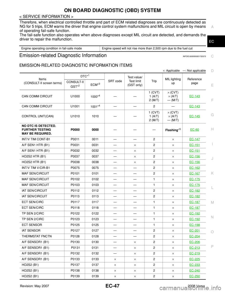
Emission-related Diagnostic InformationINFOID:0000000001702575
EMISSION-RELATED DIAGNOSTIC INFORMATION ITEMS
×: Applicable —: Not applicable
Engine operating condition in fail-safe mode Engine speed will not rise more than 2,500 rpm due to the fuel cut
Items
(CONSULT-II screen terms)DTC*
1
SRT codeTest value/
Test limit
(GST only)TripMIL lighting
upReference
page CONSULT-II
GST*
2ECM*3
CAN COMM CIRCUIT U1000
1000*4——1 (CVT)
1 (A/T)
2 (M/T)× (CVT)
× (A/T)
— (M/T)EC-143
CAN COMM CIRCUIT U1001
1001*4——2—EC-143
CONTROL UNIT(CAN) U1010 1010 — —1 (CVT)
1 (A/T)
2 (M/T)× (CVT)
× (A/T)
— (M/T)EC-145
NO DTC IS DETECTED.
FURTHER TESTING
MAY BE REQUIRED.P0000 0000———
Flashing*5EC-60
INT/V TIM CONT-B1 P0011 0011 — — 2×EC-147
A/F SEN1 HTR (B1) P0031 0031 —×2×EC-151
A/F SEN1 HTR (B1) P0032 0032 —×2×EC-151
HO2S2 HTR (B1) P0037 0037 —×2×EC-156
HO2S2 HTR (B1) P0038 0038 —×2×EC-156
INT/V TIM V/CIR-B1 P0075 0075 — — 2×EC-162
MAF SEN/CIRCUIT P0101 0101 — — 2×EC-167
MAF SEN/CIRCUIT P0102 0102 — — 1×EC-175
MAF SEN/CIRCUIT P0103 0103 — — 1×EC-175
IAT SEN/CIRCUIT P0112 0112 — — 2×EC-182
IAT SEN/CIRCUIT P0113 0113 — — 2×EC-182
ECT SEN/CIRC P0117 0117 — — 1×EC-187
ECT SEN/CIRC P0118 0118 — — 1×EC-187
TP SEN 2/CIRC P0122 0122 — — 1×EC-192
TP SEN 2/CIRC P0123 0123 — — 1×EC-192
ECT SENSOR P0125 0125 — — 1×EC-198
IAT SENSOR P0127 0127 — — 2×EC-201
THERMSTAT FNCTN P0128 0128 — — 2×EC-204
A/F SENSOR1 (B1) P0130 0130 —×2×EC-206
A/F SENSOR1 (B1) P0131 0131 —×2×EC-213
A/F SENSOR1 (B1) P0132 0132 —×2×EC-219
A/F SENSOR1 (B1) P0133 0133××2×EC-225
HO2S2 (B1) P0137 0137××2×EC-233
HO2S2 (B1) P0138 0138××2×EC-240
HO2S2 (B1) P0139 0139××2×EC-250