2008 NISSAN TIIDA Engine Control System
[x] Cancel search: Engine Control SystemPage 1084 of 2771
EC-10
< SERVICE INFORMATION >
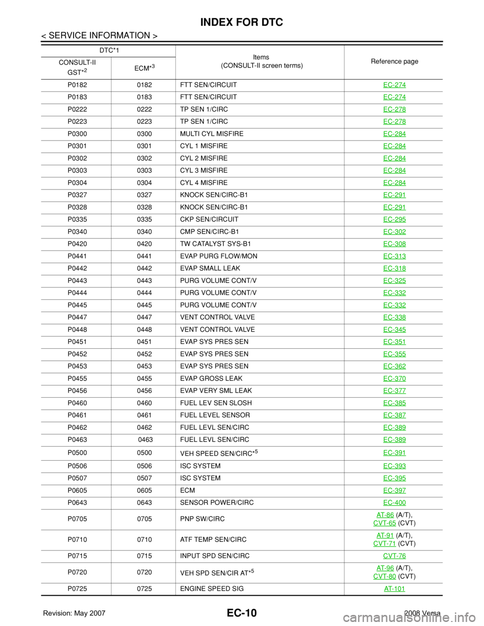
INDEX FOR DTC
P0182 0182 FTT SEN/CIRCUITEC-274
P0183 0183 FTT SEN/CIRCUITEC-274
P0222 0222 TP SEN 1/CIRCEC-278
P0223 0223 TP SEN 1/CIRCEC-278
P0300 0300 MULTI CYL MISFIREEC-284
P0301 0301 CYL 1 MISFIREEC-284
P0302 0302 CYL 2 MISFIREEC-284
P0303 0303 CYL 3 MISFIREEC-284
P0304 0304 CYL 4 MISFIREEC-284
P0327 0327 KNOCK SEN/CIRC-B1EC-291
P0328 0328 KNOCK SEN/CIRC-B1EC-291
P0335 0335 CKP SEN/CIRCUITEC-295
P0340 0340 CMP SEN/CIRC-B1EC-302
P0420 0420 TW CATALYST SYS-B1EC-308
P0441 0441 EVAP PURG FLOW/MONEC-313
P0442 0442 EVAP SMALL LEAKEC-318
P0443 0443 PURG VOLUME CONT/VEC-325
P0444 0444 PURG VOLUME CONT/VEC-332
P0445 0445 PURG VOLUME CONT/VEC-332
P0447 0447 VENT CONTROL VALVEEC-338
P0448 0448 VENT CONTROL VALVEEC-345
P0451 0451 EVAP SYS PRES SENEC-351
P0452 0452 EVAP SYS PRES SENEC-355
P0453 0453 EVAP SYS PRES SENEC-362
P0455 0455 EVAP GROSS LEAKEC-370
P0456 0456 EVAP VERY SML LEAKEC-377
P0460 0460 FUEL LEV SEN SLOSHEC-385
P0461 0461 FUEL LEVEL SENSOREC-387
P0462 0462 FUEL LEVL SEN/CIRCEC-389
P0463 0463 FUEL LEVL SEN/CIRCEC-389
P0500 0500
VEH SPEED SEN/CIRC*5EC-391
P0506 0506 ISC SYSTEMEC-393
P0507 0507 ISC SYSTEMEC-395
P0605 0605 ECMEC-397
P0643 0643 SENSOR POWER/CIRCEC-400
P0705 0705 PNP SW/CIRCAT- 8 6 (A/T),
CVT-65
(CVT)
P0710 0710 ATF TEMP SEN/CIRCAT- 9 1
(A/T),
CVT-71
(CVT)
P0715 0715 INPUT SPD SEN/CIRCCVT-76
P0720 0720
VEH SPD SEN/CIR AT*5AT- 9 6 (A/T),
CVT-80
(CVT)
P0725 0725 ENGINE SPEED SIGAT- 1 0 1
DTC*1
Items
(CONSULT-II screen terms)Reference page
CONSULT-II
GST*
2ECM*3
Page 1090 of 2771
EC-16
< SERVICE INFORMATION >
PRECAUTIONS
PRECAUTIONS
Precaution for Supplemental Restraint System (SRS) "AIR BAG" and "SEAT BELT
PRE-TENSIONER"
INFOID:0000000001702548
The Supplemental Restraint System such as “AIR BAG” and “SEAT BELT PRE-TENSIONER”, used along
with a front seat belt, helps to reduce the risk or severity of injury to the driver and front passenger for certain
types of collision. This system includes seat belt switch inputs and dual stage front air bag modules. The SRS
system uses the seat belt switches to determine the front air bag deployment, and may only deploy one front
air bag, depending on the severity of a collision and whether the front occupants are belted or unbelted.
Information necessary to service the system safely is included in the SRS and SB section of this Service Man-
ual.
WARNING:
• To avoid rendering the SRS inoperative, which could increase the risk of personal injury or death in
the event of a collision which would result in air bag inflation, all maintenance must be performed by
an authorized NISSAN/INFINITI dealer.
• Improper maintenance, including incorrect removal and installation of the SRS, can lead to personal
injury caused by unintentional activation of the system. For removal of Spiral Cable and Air Bag
Module, see the SRS section.
• Do not use electrical test equipment on any circuit related to the SRS unless instructed to in this
Service Manual. SRS wiring harnesses can be identified by yellow and/or orange harnesses or har-
ness connectors.
Precaution for Procedure without Cowl Top CoverINFOID:0000000001702549
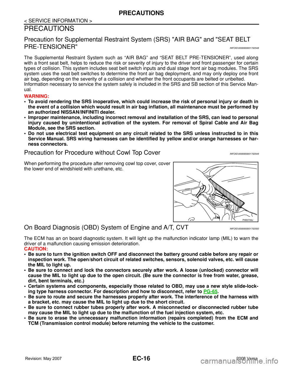
When performing the procedure after removing cowl top cover, cover
the lower end of windshield with urethane, etc.
On Board Diagnosis (OBD) System of Engine and A/T, CVTINFOID:0000000001702550
The ECM has an on board diagnostic system. It will light up the malfunction indicator lamp (MIL) to warn the
driver of a malfunction causing emission deterioration.
CAUTION:
• Be sure to turn the ignition switch OFF and disconnect the battery ground cable before any repair or
inspection work. The open/short circuit of related switches, sensors, solenoid valves, etc. will cause
the MIL to light up.
• Be sure to connect and lock the connectors securely after work. A loose (unlocked) connector will
cause the MIL to light up due to the open circuit. (Be sure the connector is free from water, grease,
dirt, bent terminals, etc.)
• Certain systems and components, especially those related to OBD, may use a new style slide-lock-
ing type harness connector. For description and how to disconnect, refer to PG-65
.
• Be sure to route and secure the harnesses properly after work. The interference of the harness with
a bracket, etc. may cause the MIL to light up due to the short circuit.
• Be sure to connect rubber tubes properly after work. A misconnected or disconnected rubber tube
may cause the MIL to light up due to the malfunction of the fuel injection system, etc.
• Be sure to erase the unnecessary malfunction information (repairs completed) from the ECM and
TCM (Transmission control module) before returning the vehicle to the customer.
PIIB3706J
Page 1091 of 2771
PRECAUTIONS
EC-17
< SERVICE INFORMATION >
C
D
E
F
G
H
I
J
K
L
MA
EC
N
P O
PrecautionINFOID:0000000001702551
•Always use a 12 volt battery as power source.
•Do not attempt to disconnect battery cables while engine is
running.
•Before connecting or disconnecting the ECM harness con-
nector, turn ignition switch OFF and disconnect negative bat-
tery cable. Failure to do so may damage the ECM because
battery voltage is applied to ECM even if ignition switch is
turned OFF.
•Before removing parts, turn ignition switch OFF and then dis-
connect negative battery cable.
•Do not disassemble ECM.
•If battery cable is disconnected, the memory will return to the
initial ECM values.
The ECM will now start to self-control at its initial values.
Engine operation can vary slightly when the cable is discon-
nected. However, this is not an indication of a malfunction. Do
not replace parts because of a slight variation.
•If the battery is disconnected, the following emission-related
diagnostic information will be lost within 24 hours.
-Diagnostic trouble codes
-1st trip diagnostic trouble codes
-Freeze frame data
-1st trip freeze frame data
-System readiness test (SRT) codes
-Test values
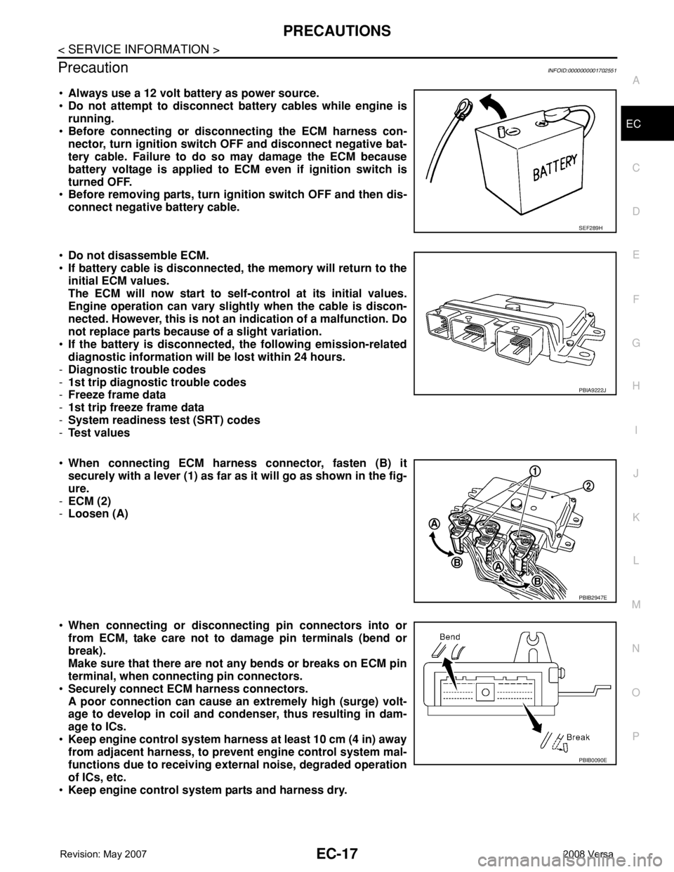
•When connecting ECM harness connector, fasten (B) it
securely with a lever (1) as far as it will go as shown in the fig-
ure.
-ECM (2)
-Loosen (A)
•When connecting or disconnecting pin connectors into or
from ECM, take care not to damage pin terminals (bend or
break).
Make sure that there are not any bends or breaks on ECM pin
terminal, when connecting pin connectors.
•Securely connect ECM harness connectors.
A poor connection can cause an extremely high (surge) volt-
age to develop in coil and condenser, thus resulting in dam-
age to ICs.
•Keep engine control system harness at least 10 cm (4 in) away
from adjacent harness, to prevent engine control system mal-
functions due to receiving external noise, degraded operation
of ICs, etc.
•Keep engine control system parts and harness dry.
SEF289H
PBIA9222J
PBIB2947E
PBIB0090E
Page 1093 of 2771
PRECAUTIONS
EC-19
< SERVICE INFORMATION >
C
D
E
F
G
H
I
J
K
L
MA
EC
N
P O
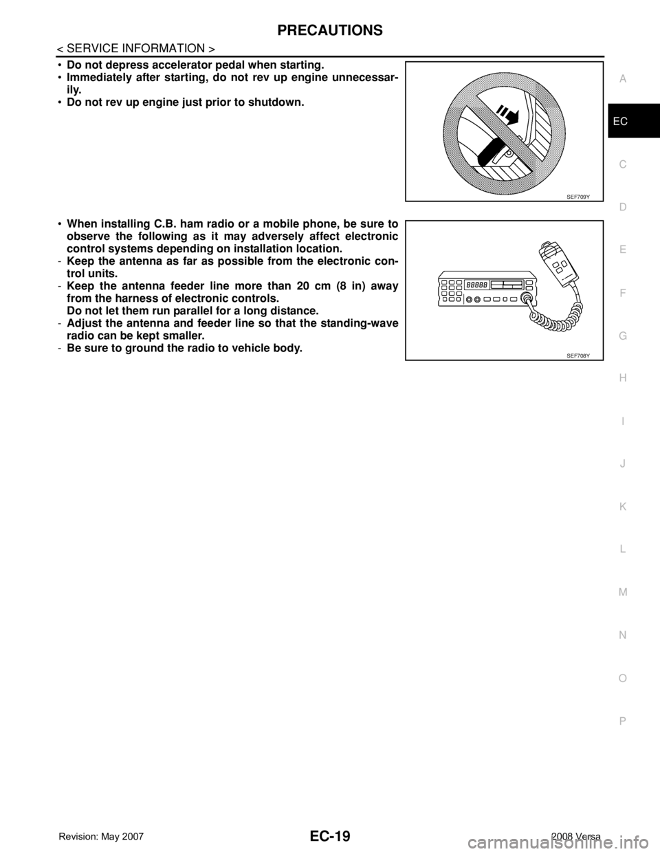
•Do not depress accelerator pedal when starting.
•Immediately after starting, do not rev up engine unnecessar-
ily.
•Do not rev up engine just prior to shutdown.
•When installing C.B. ham radio or a mobile phone, be sure to
observe the following as it may adversely affect electronic
control systems depending on installation location.
-Keep the antenna as far as possible from the electronic con-
trol units.
-Keep the antenna feeder line more than 20 cm (8 in) away
from the harness of electronic controls.
Do not let them run parallel for a long distance.
-Adjust the antenna and feeder line so that the standing-wave
radio can be kept smaller.
-Be sure to ground the radio to vehicle body.
SEF709Y
SEF708Y
Page 1096 of 2771
EC-22
< SERVICE INFORMATION >
ENGINE CONTROL SYSTEM
ENGINE CONTROL SYSTEM
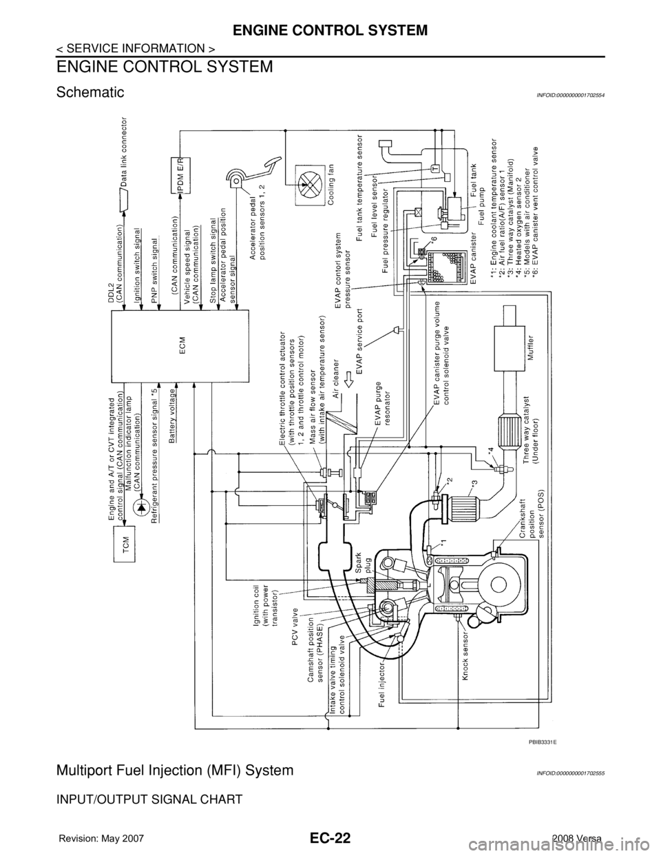
SchematicINFOID:0000000001702554
Multiport Fuel Injection (MFI) SystemINFOID:0000000001702555
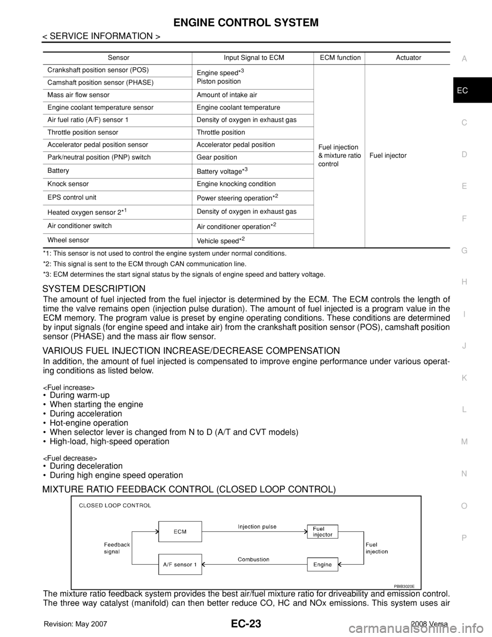
INPUT/OUTPUT SIGNAL CHART
PBIB3331E
Page 1097 of 2771
ENGINE CONTROL SYSTEM
EC-23
< SERVICE INFORMATION >
C
D
E
F
G
H
I
J
K
L
MA
EC
N
P O
*1: This sensor is not used to control the engine system under normal conditions.
*2: This signal is sent to the ECM through CAN communication line.
*3: ECM determines the start signal status by the signals of engine speed and battery voltage.
SYSTEM DESCRIPTION
The amount of fuel injected from the fuel injector is determined by the ECM. The ECM controls the length of
time the valve remains open (injection pulse duration). The amount of fuel injected is a program value in the
ECM memory. The program value is preset by engine operating conditions. These conditions are determined
by input signals (for engine speed and intake air) from the crankshaft position sensor (POS), camshaft position
sensor (PHASE) and the mass air flow sensor.
VARIOUS FUEL INJECTION INCREASE/DECREASE COMPENSATION
In addition, the amount of fuel injected is compensated to improve engine performance under various operat-
ing conditions as listed below.
• When starting the engine
• During acceleration
• Hot-engine operation
• When selector lever is changed from N to D (A/T and CVT models)
• High-load, high-speed operation
• During deceleration
• During high engine speed operation
MIXTURE RATIO FEEDBACK CONTROL (CLOSED LOOP CONTROL)
The mixture ratio feedback system provides the best air/fuel mixture ratio for driveability and emission control.
The three way catalyst (manifold) can then better reduce CO, HC and NOx emissions. This system uses air
Sensor Input Signal to ECM ECM function Actuator
Crankshaft position sensor (POS)
Engine speed*
3
Piston position
Fuel injection
& mixture ratio
controlFuel injector Camshaft position sensor (PHASE)
Mass air flow sensor Amount of intake air
Engine coolant temperature sensor Engine coolant temperature
Air fuel ratio (A/F) sensor 1 Density of oxygen in exhaust gas
Throttle position sensor Throttle position
Accelerator pedal position sensor Accelerator pedal position
Park/neutral position (PNP) switch Gear position
Battery
Battery voltage*
3
Knock sensor Engine knocking condition
EPS control unit
Power steering operation*
2
Heated oxygen sensor 2*1Density of oxygen in exhaust gas
Air conditioner switch
Air conditioner operation*
2
Wheel sensor
Vehicle speed*2
PBIB3020E
Page 1098 of 2771
EC-24
< SERVICE INFORMATION >
ENGINE CONTROL SYSTEM
fuel ratio (A/F) sensor 1 in the exhaust manifold to monitor whether the engine operation is rich or lean. The
ECM adjusts the injection pulse width according to the sensor voltage signal. For more information about air
fuel ratio (A/F) sensor 1, refer to EC-213
. This maintains the mixture ratio within the range of stoichiometric
(ideal air/fuel mixture).
This stage is referred to as the closed loop control condition.
Heated oxygen sensor 2 is located downstream of the three way catalyst (manifold). Even if the switching
characteristics of air fuel ratio (A/F) sensor 1 shift, the air/fuel ratio is controlled to stoichiometric by the signal
from heated oxygen sensor 2.
Open Loop Control
The open loop system condition refers to when the ECM detects any of the following conditions. Feedback
control stops in order to maintain stabilized fuel combustion.
• Deceleration and acceleration
• High-load, high-speed operation
• Malfunction of air fuel ratio (A/F) sensor 1 or its circuit
• Insufficient activation of air fuel ratio (A/F) sensor 1 at low engine coolant temperature
• High engine coolant temperature
• During warm-up
• After shifting from N to D (A/T and CVT models)
• When starting the engine
MIXTURE RATIO SELF-LEARNING CONTROL
The mixture ratio feedback control system monitors the mixture ratio signal transmitted from air fuel ratio (A/F)
sensor 1. This feedback signal is then sent to the ECM. The ECM controls the basic mixture ratio as close to
the theoretical mixture ratio as possible. However, the basic mixture ratio is not necessarily controlled as orig-
inally designed. Both manufacturing differences (i.e., mass air flow sensor hot wire) and characteristic
changes during operation (i.e., fuel injector clogging) directly affect mixture ratio.
Accordingly, the difference between the basic and theoretical mixture ratios is monitored in this system. This is
then computed in terms of “injection pulse duration” to automatically compensate for the difference between
the two ratios.
“Fuel trim” refers to the feedback compensation value compared against the basic injection duration. Fuel trim
includes short term fuel trim and long term fuel trim.
“Short term fuel trim” is the short-term fuel compensation used to maintain the mixture ratio at its theoretical
value. The signal from air fuel ratio (A/F) sensor 1 indicates whether the mixture ratio is RICH or LEAN com-
pared to the theoretical value. The signal then triggers a reduction in fuel volume if the mixture ratio is rich, and
an increase in fuel volume if it is lean.
“Long term fuel trim” is overall fuel compensation carried out long-term to compensate for continual deviation
of the short term fuel trim from the central value. Such deviation will occur due to individual engine differences,
wear over time and changes in the usage environment.
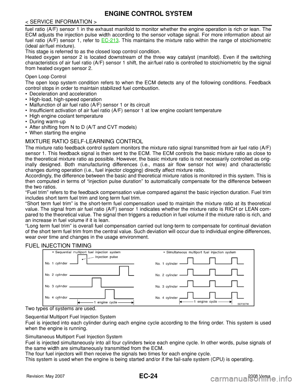
FUEL INJECTION TIMING
Two types of systems are used.
Sequential Multiport Fuel Injection System
Fuel is injected into each cylinder during each engine cycle according to the firing order. This system is used
when the engine is running.
Simultaneous Multiport Fuel Injection System
Fuel is injected simultaneously into all four cylinders twice each engine cycle. In other words, pulse signals of
the same width are simultaneously transmitted from the ECM.
The four fuel injectors will then receive the signals two times for each engine cycle.
This system is used when the engine is being started and/or if the fail-safe system (CPU) is operating.
SEF337W
Page 1099 of 2771

ENGINE CONTROL SYSTEM
EC-25
< SERVICE INFORMATION >
C
D
E
F
G
H
I
J
K
L
MA
EC
N
P O
FUEL SHUT-OFF
Fuel to each cylinder is cut off during deceleration, operation of the engine at excessively high speeds or oper-
ation of the vehicle at excessively high speeds.
Electronic Ignition (EI) SystemINFOID:0000000001702556
INPUT/OUTPUT SIGNAL CHART
*1: This signal is sent to the ECM through CAN communication line.
*2: ECM determines the start signal status by the signals of engine speed and battery voltage.
SYSTEM DESCRIPTION
Firing order: 1 - 3 - 4 - 2
The ignition timing is controlled by the ECM to maintain the best air-fuel ratio for every running condition of the
engine. The ignition timing data is stored in the ECM.
The ECM receives information such as the injection pulse width and camshaft position sensor (PHASE) sig-
nal. Computing this information, ignition signals are transmitted to the power transistor.
During the following conditions, the ignition timing is revised by the ECM according to the other data stored in
the ECM.
• At starting
• During warm-up
•At idle
• At low battery voltage
• During acceleration
The knock sensor retard system is designed only for emergencies. The basic ignition timing is programmed
within the anti-knocking zone, if recommended fuel is used under dry conditions. The retard system does not
operate under normal driving conditions. If engine knocking occurs, the knock sensor monitors the condition.
The signal is transmitted to the ECM. The ECM retards the ignition timing to eliminate the knocking condition.
Fuel Cut Control (at No Load and High Engine Speed)INFOID:0000000001702557
INPUT/OUTPUT SIGNAL CHART
*: This signal is sent to the ECM through CAN communication line.
SYSTEM DESCRIPTION
Sensor Input Signal to ECM ECM function Actuator
Crankshaft position sensor (POS)
Engine speed*
2
Piston position
Ignition timing
controlPower transistor Camshaft position sensor (PHASE)
Mass air flow sensor Amount of intake air
Engine coolant temperature sensor Engine coolant temperature
Throttle position sensor Throttle position
Accelerator pedal position sensor Accelerator pedal position
Battery
Battery voltage*
2
Knock sensor Engine knocking
Park/neutral position (PNP) switch Gear position
Wheel sensor
Vehicle speed*
1
Sensor Input Signal to ECM ECM function Actuator
Park/neutral position (PNP) switch Neutral position
Fuel cut control Fuel injector Accelerator pedal position sensor Accelerator pedal position
Engine coolant temperature sensor Engine coolant temperature
Crankshaft position sensor (POS)
Camshaft position sensor (PHASE)Engine speed
Wheel sensor Vehicle speed*