2008 NISSAN TEANA engine
[x] Cancel search: enginePage 3221 of 5121
CHASSIS MAINTENANCE
MA-33
< ON-VEHICLE MAINTENANCE >
C
D
E
F
G
H
I
J
K
L
MB
MAN
OA
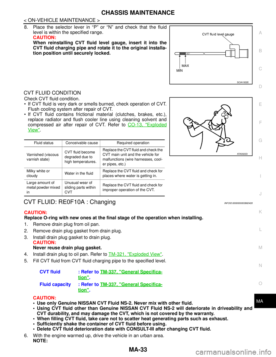
8. Place the selector lever in “P” or “N” and check that the fluid
level is within the specified range.
CAUTION:
When reinstalling CVT fluid level gauge, insert it into the
CVT fluid charging pipe and rotate it to the original installa-
tion position until securely locked.
CVT FLUID CONDITION
Check CVT fluid condition.
If CVT fluid is very dark or smells burned, check operation of CVT.
Flush cooling system after repair of CVT.
If CVT fluid contains frictional material (clutches, brakes, etc.),
replace radiator and flush cooler line using cleaning solvent and
compressed air after repair of CVT. Refer to CO-13, "
Exploded
View".
CVT FLUID: RE0F10A : ChangingINFOID:0000000003862428
CAUTION:
Replace O-ring with new ones at the final stage of the operation when installing.
1. Remove drain plug from oil pan.
2. Remove drain plug gasket from drain plug.
3. Install drain plug gasket to drain plug.
CAUTION:
Never reuse drain plug gasket.
4. Install drain plug to oil pan. Refer to TM-321, "
Exploded View".
5. Fill CVT fluid from CVT fluid charging pipe to the specified level.
CAUTION:
Use only Genuine NISSAN CVT Fluid NS-2. Never mix with other fluid.
Using CVT fluid other than Genuine NISSAN CVT Fluid NS-2 will deteriorate in driveability and
CVT durability, and may damage the CVT, which is not covered by the warranty.
When filling CVT fluid, take care not to scatter heat generating parts such as exhaust.
Sufficiently shake the container of CVT fluid before using.
Delete CVT fluid deterioration date with CONSULT-III after changing CVT fluid.
6. With the engine warmed up, drive the vehicle in an urban area.
NOTE:
SCIA1932E
Fluid status Conceivable cause Required operation
Varnished (viscous
varnish state)CVT fluid become
degraded due to
high temperatures.Replace the CVT fluid and check the
CVT main unit and the vehicle for
malfunctions (wire harnesses, cool-
er pipes, etc.)
Milky white or
cloudyWater in the fluidReplace the CVT fluid and check for
places where water is getting in.
Large amount of
metal powder mixed
inUnusual wear of
sliding parts within
CVTReplace the CVT fluid and check for
improper operation of the CVT.
ATA0022D
CVT fluid : Refer to TM-337, "General Specifica-
tion".
Fluid capacity : Refer to TM-337, "
General Specifica-
tion".
Page 3222 of 5121
MA-34
< ON-VEHICLE MAINTENANCE >
CHASSIS MAINTENANCE
When ambient temperature is 20°C (68°F), it takes about 10 minutes for the CVT fluid to warm up to 50 to
80°C (122 to 176°F).
7. Check CVT fluid level and condition.
8. Repeat steps 1 to 5 if CVT fluid has been contaminated.
CVT FLUID: RE0F09B
CVT FLUID: RE0F09B : InspectionINFOID:0000000003862429
CHECKING CVT FLUID
The fluid level should be checked with the fluid warmed up to 50 to 80°C (122 to 176°F). The fluid level check
procedure is as follows:
1. Check for fluid leakage.
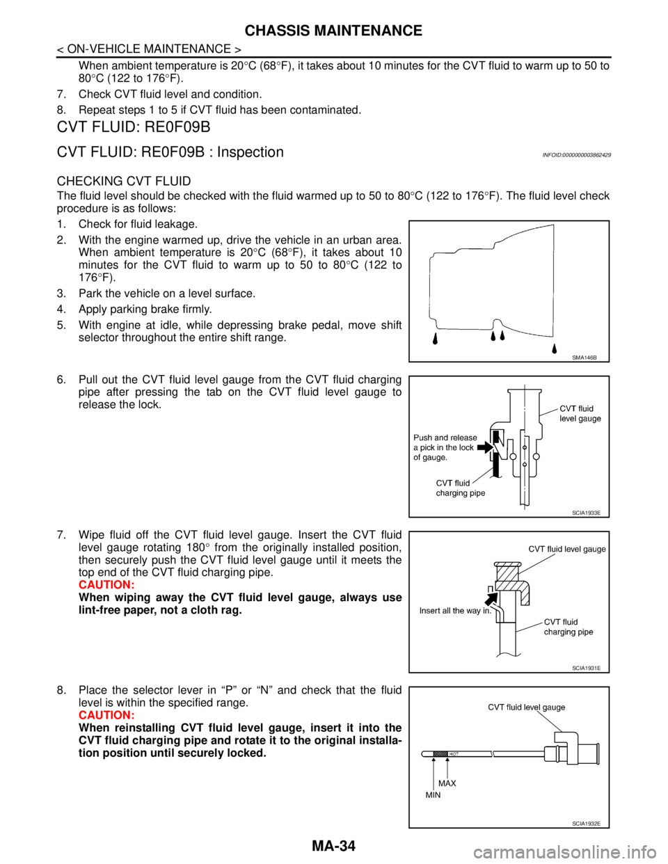
2. With the engine warmed up, drive the vehicle in an urban area.
When ambient temperature is 20°C (68°F), it takes about 10
minutes for the CVT fluid to warm up to 50 to 80°C (122 to
176°F).
3. Park the vehicle on a level surface.
4. Apply parking brake firmly.
5. With engine at idle, while depressing brake pedal, move shift
selector throughout the entire shift range.
6. Pull out the CVT fluid level gauge from the CVT fluid charging
pipe after pressing the tab on the CVT fluid level gauge to
release the lock.
7. Wipe fluid off the CVT fluid level gauge. Insert the CVT fluid
level gauge rotating 180° from the originally installed position,
then securely push the CVT fluid level gauge until it meets the
top end of the CVT fluid charging pipe.
CAUTION:
When wiping away the CVT fluid level gauge, always use
lint-free paper, not a cloth rag.
8. Place the selector lever in “P” or “N” and check that the fluid
level is within the specified range.
CAUTION:
When reinstalling CVT fluid level gauge, insert it into the
CVT fluid charging pipe and rotate it to the original installa-
tion position until securely locked.
SMA146B
SCIA1933E
SCIA1931E
SCIA1932E
Page 3223 of 5121
CHASSIS MAINTENANCE
MA-35
< ON-VEHICLE MAINTENANCE >
C
D
E
F
G
H
I
J
K
L
MB
MAN
OA
CVT FLUID CONDITION
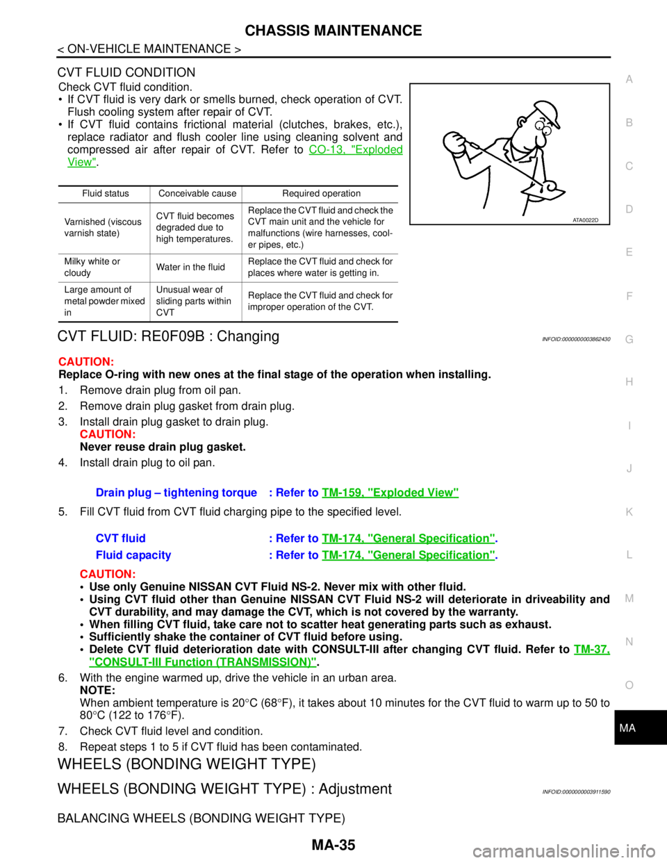
Check CVT fluid condition.
If CVT fluid is very dark or smells burned, check operation of CVT.
Flush cooling system after repair of CVT.
If CVT fluid contains frictional material (clutches, brakes, etc.),
replace radiator and flush cooler line using cleaning solvent and
compressed air after repair of CVT. Refer to CO-13, "
Exploded
View".
CVT FLUID: RE0F09B : ChangingINFOID:0000000003862430
CAUTION:
Replace O-ring with new ones at the final stage of the operation when installing.
1. Remove drain plug from oil pan.
2. Remove drain plug gasket from drain plug.
3. Install drain plug gasket to drain plug.
CAUTION:
Never reuse drain plug gasket.
4. Install drain plug to oil pan.
5. Fill CVT fluid from CVT fluid charging pipe to the specified level.
CAUTION:
Use only Genuine NISSAN CVT Fluid NS-2. Never mix with other fluid.
Using CVT fluid other than Genuine NISSAN CVT Fluid NS-2 will deteriorate in driveability and
CVT durability, and may damage the CVT, which is not covered by the warranty.
When filling CVT fluid, take care not to scatter heat generating parts such as exhaust.
Sufficiently shake the container of CVT fluid before using.
Delete CVT fluid deterioration date with CONSULT-III after changing CVT fluid. Refer to TM-37,
"CONSULT-III Function (TRANSMISSION)".
6. With the engine warmed up, drive the vehicle in an urban area.
NOTE:
When ambient temperature is 20°C (68°F), it takes about 10 minutes for the CVT fluid to warm up to 50 to
80°C (122 to 176°F).
7. Check CVT fluid level and condition.
8. Repeat steps 1 to 5 if CVT fluid has been contaminated.
WHEELS (BONDING WEIGHT TYPE)
WHEELS (BONDING WEIGHT TYPE) : AdjustmentINFOID:0000000003911590
BALANCING WHEELS (BONDING WEIGHT TYPE)
Fluid status Conceivable cause Required operation
Varnished (viscous
varnish state)CVT fluid becomes
degraded due to
high temperatures.Replace the CVT fluid and check the
CVT main unit and the vehicle for
malfunctions (wire harnesses, cool-
er pipes, etc.)
Milky white or
cloudyWater in the fluidReplace the CVT fluid and check for
places where water is getting in.
Large amount of
metal powder mixed
inUnusual wear of
sliding parts within
CVTReplace the CVT fluid and check for
improper operation of the CVT.
ATA0022D
Drain plug – tightening torque : Refer to TM-159, "Exploded View"
CVT fluid : Refer to TM-174, "General Specification".
Fluid capacity : Refer to TM-174, "
General Specification".
Page 3228 of 5121
MA-40
< ON-VEHICLE MAINTENANCE >
CHASSIS MAINTENANCE
POWER STEERING FLUID AND LINES : Inspection
INFOID:0000000003862441
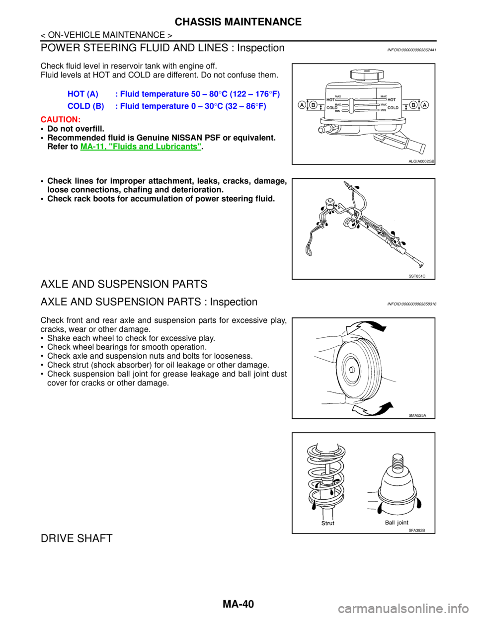
Check fluid level in reservoir tank with engine off.
Fluid levels at HOT and COLD are different. Do not confuse them.
CAUTION:
Do not overfill.
Recommended fluid is Genuine NISSAN PSF or equivalent.
Refer to MA-11, "
Fluids and Lubricants".
Check lines for improper attachment, leaks, cracks, damage,
loose connections, chafing and deterioration.
Check rack boots for accumulation of power steering fluid.
AXLE AND SUSPENSION PARTS
AXLE AND SUSPENSION PARTS : InspectionINFOID:0000000003858316
Check front and rear axle and suspension parts for excessive play,
cracks, wear or other damage.
Shake each wheel to check for excessive play.
Check wheel bearings for smooth operation.
Check axle and suspension nuts and bolts for looseness.
Check strut (shock absorber) for oil leakage or other damage.
Check suspension ball joint for grease leakage and ball joint dust
cover for cracks or other damage.
DRIVE SHAFT
HOT (A) : Fluid temperature 50 – 80°C (122 – 176°F)
COLD (B) : Fluid temperature 0 – 30°C (32 – 86°F)
ALGIA0002GB
SST851C
SMA525A
SFA392B
Page 3230 of 5121
MA-42
< ON-VEHICLE MAINTENANCE >
BODY MAINTENANCE
BODY MAINTENANCE
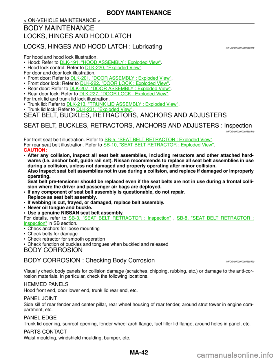
LOCKS, HINGES AND HOOD LATCH
LOCKS, HINGES AND HOOD LATCH : LubricatingINFOID:0000000003858318
For hood and hood lock illustration.
Hood: Refer to DLK-191, "
HOOD ASSEMBLY : Exploded View".
Hood lock control: Refer to DLK-220, "
Exploded View".
For door and door lock illustration.
Front door: Refer to DLK-201, "
DOOR ASSEMBLY : Exploded View".
Front door lock: Refer to DLK-222, "
DOOR LOCK : Exploded View".
Rear door: Refer to DLK-207, "
DOOR ASSEMBLY : Exploded View".
Rear door lock: Refer to DLK-227, "
DOOR LOCK : Exploded View".
For trunk lid and trunk lid lock illustration.
Trunk lid: Refer to DLK-213, "
TRUNK LID ASSEMBLY : Exploded View".
Trunk lid lock: Refer to DLK-231, "
Exploded View".
SEAT BELT, BUCKLES, RETRACTORS, ANCHORS AND ADJUSTERS
SEAT BELT, BUCKLES, RETRACTORS, ANCHORS AND ADJUSTERS : Inspection
INFOID:0000000003858319
For front seat belt illustration. Refer to SB-5, "SEAT BELT RETRACTOR : Exploded View".
For rear seat belt illustration. Refer to SB-10, "
SEAT BELT RETRACTOR : Exploded View".
CAUTION:
After any collision, inspect all seat belt assemblies, including retractors and other attached hard-
wares (I.e. anchor bolt, guide rail set). Nissan recommends to replace all seat belt assemblies in use
during a collision, unless not damaged and properly operating after minor collision.
Also inspect seat belt assemblies not in use during a collision, and replace if damaged or improperly
operating.
Seat belt pre-tensioner should be replaced even if the seat belts are not in use during a frontal colli-
sion where the driver and passenger air bags are deployed.
If any component of seat belt assembly is questionable, do not repair.
Replace as seat belt assembly.
If webbing is cut, frayed, or damaged, replace belt assembly.
Never oil tongue and buckle.
Use a genuine NISSAN seat belt assembly.
For details, refer to SB-3, "
SEAT BELT RETRACTOR : Inspection" , SB-8, "SEAT BELT RETRACTOR :
Inspection" in SB section.
Check anchors for loose mounting
Check belts for damage
Check retractor for smooth operation
Check function of buckles and tongues when buckled and released
BODY CORROSION
BODY CORROSION : Checking Body CorrosionINFOID:0000000003858320
Visually check body panels for collision damage (scratches, chipping, rubbing, etc.) or damage to the anti-cor-
rosion materials. In particular, check the following locations.
HEMMED PANELS
Hood front end, door lower end, trunk lid rear end, etc.
PA N E L J O I N T
Side sill of rear fender and center pillar, rear wheel housing of rear fender, around strut tower in engine com-
partment, etc.
PA N E L E D G E
Trunk lid opening, sunroof opening, fender wheel-arch flange, fuel filler lid flange, around holes in panel, etc.
PARTS CONTACT
Waist moulding, windshield moulding, bumper, etc.
Page 3232 of 5121
MA-44
< SERVICE DATA AND SPECIFICATIONS (SDS)
SERVICE DATA AND SPECIFICATIONS (SDS)
SERVICE DATA AND SPECIFICATIONS (SDS)
SERVICE DATA AND SPECIFICATIONS (SDS)
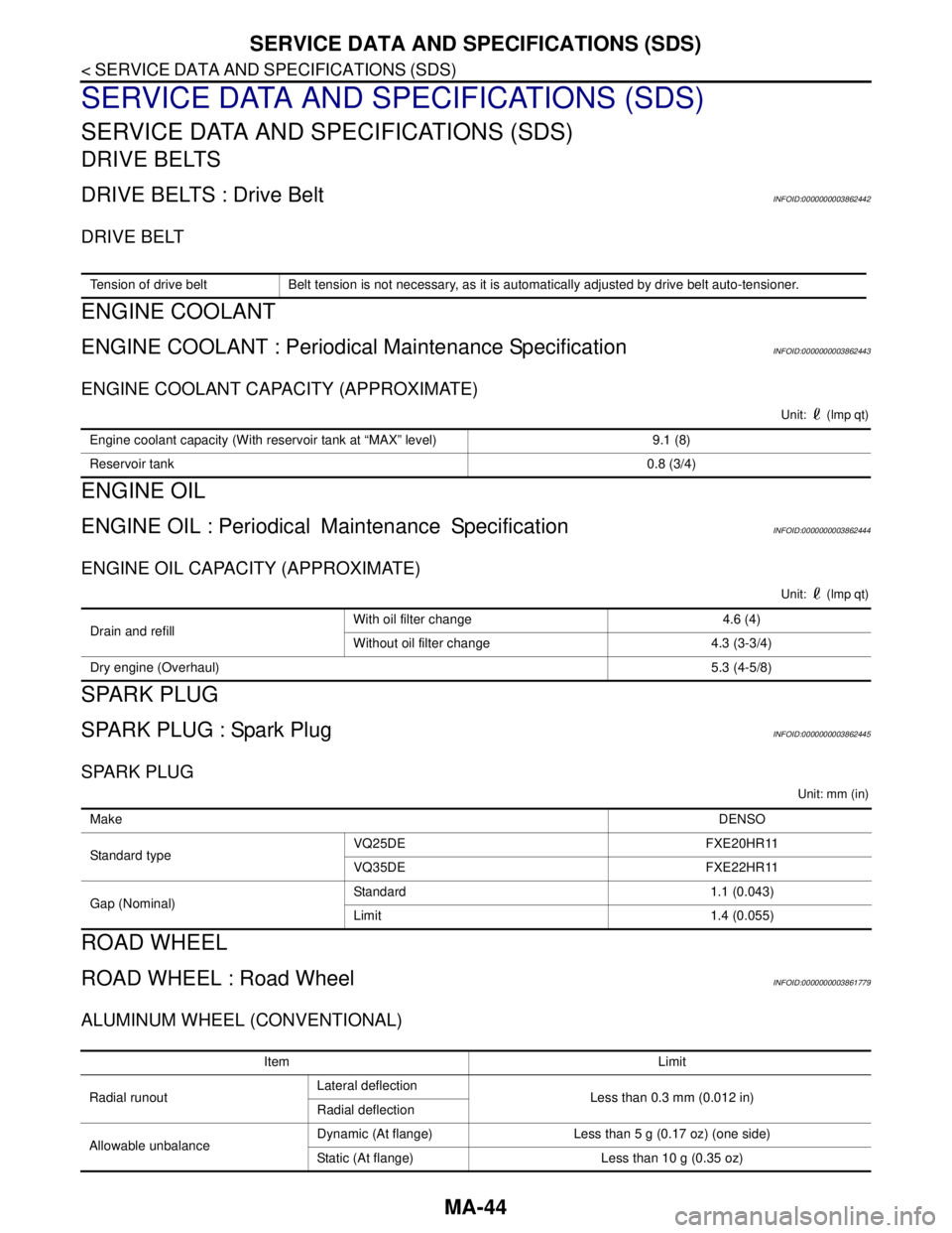
DRIVE BELTS
DRIVE BELTS : Drive BeltINFOID:0000000003862442
DRIVE BELT
ENGINE COOLANT
ENGINE COOLANT : Periodical Maintenance SpecificationINFOID:0000000003862443
ENGINE COOLANT CAPACITY (APPROXIMATE)
Unit: (lmp qt)
ENGINE OIL
ENGINE OIL : PeriodicalMaintenance SpecificationINFOID:0000000003862444
ENGINE OIL CAPACITY (APPROXIMATE)
Unit: (lmp qt)
SPARK PLUG
SPARK PLUG : Spark PlugINFOID:0000000003862445
SPARK PLUG
Unit: mm (in)
ROAD WHEEL
ROAD WHEEL : Road WheelINFOID:0000000003861779
ALUMINUM WHEEL (CONVENTIONAL)
Tension of drive belt Belt tension is not necessary, as it is automatically adjusted by drive belt auto-tensioner.
Engine coolant capacity (With reservoir tank at “MAX” level) 9.1 (8)
Reservoir tank0.8 (3/4)
Drain and refill With oil filter change 4.6 (4)
Without oil filter change 4.3 (3-3/4)
Dry engine (Overhaul)5.3 (4-5/8)
MakeDENSO
Standard typeVQ25DE FXE20HR11
VQ35DE FXE22HR11
Gap (Nominal)Standard 1.1 (0.043)
Limit 1.4 (0.055)
Item Limit
Radial runoutLateral deflection
Less than 0.3 mm (0.012 in)
Radial deflection
Allowable unbalanceDynamic (At flange) Less than 5 g (0.17 oz) (one side)
Static (At flange) Less than 10 g (0.35 oz)
Page 3240 of 5121
SQUEAK AND RATTLE TROUBLE DIAGNOSES
MIR-7
< SYMPTOM DIAGNOSIS >
C
D
E
F
G
H
I
J
K
MA
B
MIR
N
O
P
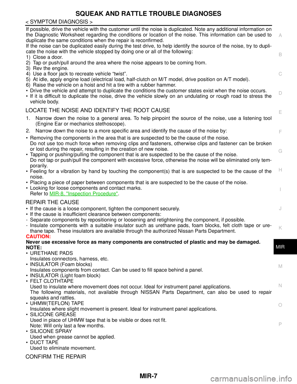
If possible, drive the vehicle with the customer until the noise is duplicated. Note any additional information on
the Diagnostic Worksheet regarding the conditions or location of the noise. This information can be used to
duplicate the same conditions when the repair is reconfirmed.
If the noise can be duplicated easily during the test drive, to help identify the source of the noise, try to dupli-
cate the noise with the vehicle stopped by doing one or all of the following:
1) Close a door.
2) Tap or push/pull around the area where the noise appears to be coming from.
3) Rev the engine.
4) Use a floor jack to recreate vehicle “twist”.
5) At idle, apply engine load (electrical load, half-clutch on M/T model, drive position on A/T model).
6) Raise the vehicle on a hoist and hit a tire with a rubber hammer.
Drive the vehicle and attempt to duplicate the conditions the customer states exist when the noise occurs.
If it is difficult to duplicate the noise, drive the vehicle slowly on an undulating or rough road to stress the
vehicle body.
LOCATE THE NOISE AND IDENTIFY THE ROOT CAUSE
1. Narrow down the noise to a general area. To help pinpoint the source of the noise, use a listening tool
(Engine Ear or mechanics stethoscope).
2. Narrow down the noise to a more specific area and identify the cause of the noise by:
Removing the components in the area that is are suspected to be the cause of the noise.
Do not use too much force when removing clips and fasteners, otherwise clips and fastener can be broken
or lost during the repair, resulting in the creation of new noise.
Tapping or pushing/pulling the component that is are suspected to be the cause of the noise.
Do not tap or push/pull the component with excessive force, otherwise the noise will be eliminated only tem-
porarily.
Feeling for a vibration by hand by touching the component(s) that is are suspected to be the cause of the
noise.
Placing a piece of paper between components that is are suspected to be the cause of the noise.
Looking for loose components and contact marks.
Refer to MIR-8, "
Inspection Procedure".
REPAIR THE CAUSE
If the cause is a loose component, tighten the component securely.
If the cause is insufficient clearance between components:
- Separate components by repositioning or loosening and retightening the component, if possible.
- Insulate components with a suitable insulator such as urethane pads, foam blocks, felt cloth tape or ure-
thane tape. These insulators are available through the authorized Nissan Parts Department.
CAUTION:
Never use excessive force as many components are constructed of plastic and may be damaged.
NOTE:
URETHANE PADS
Insulates connectors, harness, etc.
INSULATOR (Foam blocks)
Insulates components from contact. Can be used to fill space behind a panel.
INSULATOR (Light foam block)
FELT CLOTHTAPE
Used to insulate where movement does not occur. Ideal for instrument panel applications.
The following materials, not available through NISSAN Parts Department, can also be used to repair
squeaks and rattles.
UHMW(TEFLON) TAPE
Insulates where slight movement is present. Ideal for instrument panel applications.
SILICONE GREASE
Used in place of UHMW tape that is be visible or does not fit.
Note: Will only last a few months.
SILICONE SPRAY
Used when grease cannot be applied.
DUCT TAPE
Used to eliminate movement.
CONFIRM THE REPAIR
Page 3242 of 5121

SQUEAK AND RATTLE TROUBLE DIAGNOSES
MIR-9
< SYMPTOM DIAGNOSIS >
C
D
E
F
G
H
I
J
K
MA
B
MIR
N
O
P
Again, pressing on the components to stop the noise while duplicating the conditions can isolate most of these
incidents. Repairs usually consist of insulating with felt cloth tape.
SEATS
When isolating seat noise it is important to note the position the seat is in and the load placed on the seat
when the noise occurs. These conditions should be duplicated when verifying and isolating the cause of the
noise.
Cause of seat noise include:
1. Headrest rods and holder
2. A squeak between the seat pad cushion and frame
3. Rear seatback lock and bracket
These noises can be isolated by moving or pressing on the suspected components while duplicating the con-
ditions under which the noise occurs. Most of these incidents can be repaired by repositioning the component
or applying urethane tape to the contact area.
UNDERHOOD
Some interior noise may be caused by components under the hood or on the engine wall. The noise is then
transmitted into the passenger compartment.
Causes of transmitted underhood noise include:
1. Any component mounted to the engine wall
2. Components that pass through the engine wall
3. Engine wall mounts and connectors
4. Loose radiator mounting pins
5. Hood bumpers out of adjustment
6. Hood striker out of adjustment
These noises can be difficult to isolate since they cannot be reached from the interior of the vehicle. The best
method is to secure, move or insulate one component at a time and test drive the vehicle. Also, engine RPM
or load can be changed to isolate the noise. Repairs can usually be made by moving, adjusting, securing, or
insulating the component causing the noise.