Page 3276 of 5121

MWI-22
< FUNCTION DIAGNOSIS >
METER SYSTEM
SHIFT POSITION INDICATOR : Component Description
INFOID:0000000003792534
WARNING LAMPS/INDICATOR LAMPS
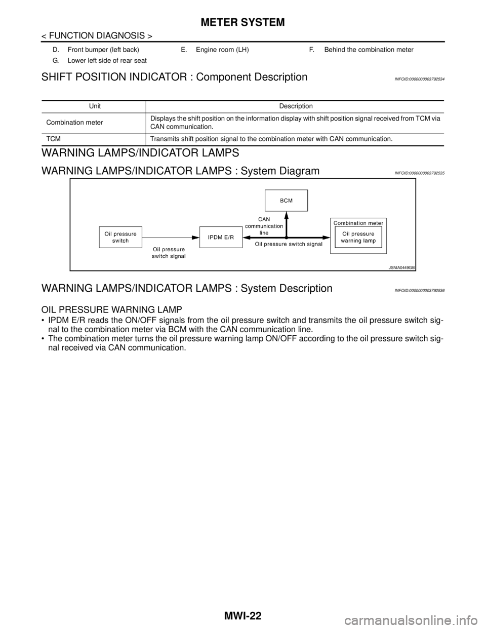
WARNING LAMPS/INDICATOR LAMPS : System DiagramINFOID:0000000003792535
WARNING LAMPS/INDICATOR LAMPS : System DescriptionINFOID:0000000003792536
OIL PRESSURE WARNING LAMP
IPDM E/R reads the ON/OFF signals from the oil pressure switch and transmits the oil pressure switch sig-
nal to the combination meter via BCM with the CAN communication line.
The combination meter turns the oil pressure warning lamp ON/OFF according to the oil pressure switch sig-
nal received via CAN communication.
D. Front bumper (left back) E. Engine room (LH) F. Behind the combination meter
G. Lower left side of rear seat
Unit Description
Combination meterDisplays the shift position on the information display with shift position signal received from TCM via
CAN communication.
TCM Transmits shift position signal to the combination meter with CAN communication.
JSNIA0449GB
Page 3277 of 5121
MWI
METER SYSTEM
MWI-23
< FUNCTION DIAGNOSIS >
C
D
E
F
G
H
I
J
K
L
MB A
O
P
WARNING LAMPS/INDICATOR LAMPS : Component Parts LocationINFOID:0000000003879662
1. ABS actuator and electric unit (con-
trol unit)2. ECM 3. TCM
4. Oil pressure switch 5. Ambient sensor 6. IPDM E/R
7. BCM 8. Combination meter 9. Fuel level sensor unit and fuel pump
A. Engine room (LH) B. Engine room (LH) C. Engine front side
JPNIA1025ZZ
Page 3278 of 5121

MWI-24
< FUNCTION DIAGNOSIS >
METER SYSTEM
WARNING LAMPS/INDICATOR LAMPS : Component Description
INFOID:0000000003792538
METER ILLUMINATION CONTROL
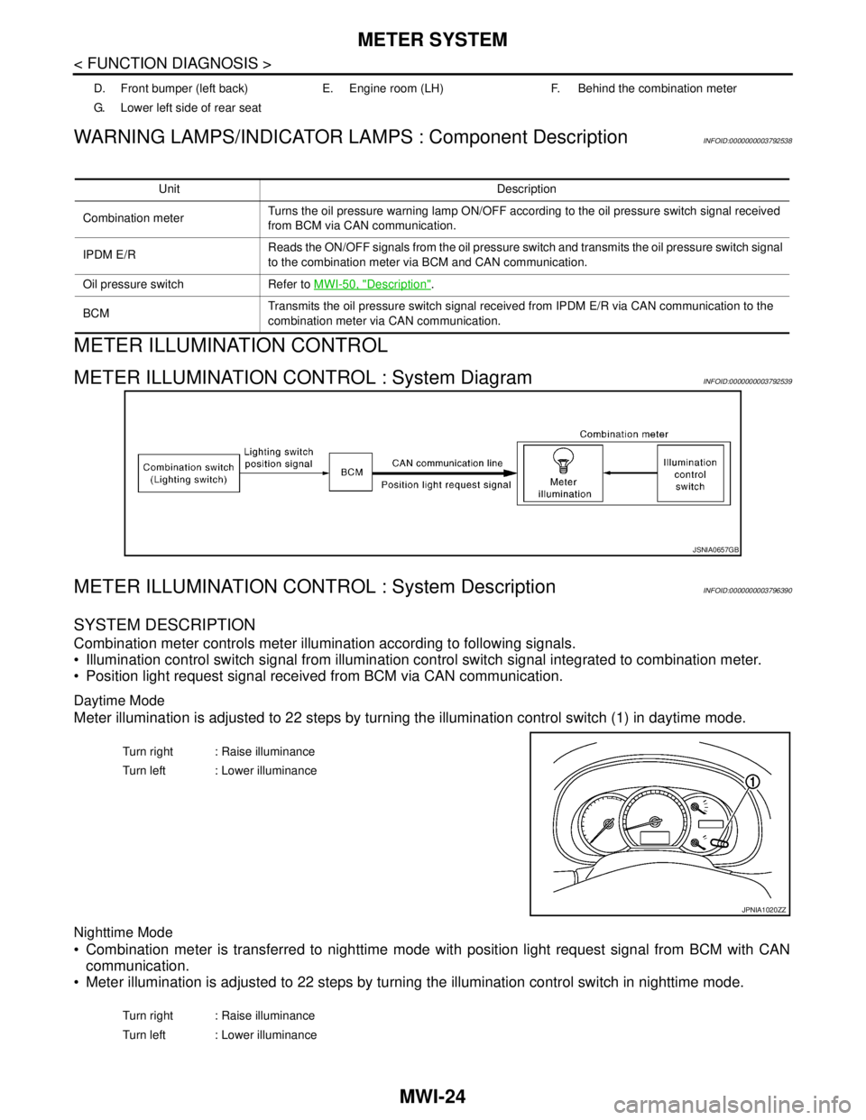
METER ILLUMINATION CONTROL : System DiagramINFOID:0000000003792539
METER ILLUMINATION CONTROL : System DescriptionINFOID:0000000003796390
SYSTEM DESCRIPTION
Combination meter controls meter illumination according to following signals.
Illumination control switch signal from illumination control switch signal integrated to combination meter.
Position light request signal received from BCM via CAN communication.
Daytime Mode
Meter illumination is adjusted to 22 steps by turning the illumination control switch (1) in daytime mode.
Nighttime Mode
Combination meter is transferred to nighttime mode with position light request signal from BCM with CAN
communication.
Meter illumination is adjusted to 22 steps by turning the illumination control switch in nighttime mode.
D. Front bumper (left back) E. Engine room (LH) F. Behind the combination meter
G. Lower left side of rear seat
Unit Description
Combination meterTurns the oil pressure warning lamp ON/OFF according to the oil pressure switch signal received
from BCM via CAN communication.
IPDM E/RReads the ON/OFF signals from the oil pressure switch and transmits the oil pressure switch signal
to the combination meter via BCM and CAN communication.
Oil pressure switch Refer to MWI-50, "
Description".
BCMTransmits the oil pressure switch signal received from IPDM E/R via CAN communication to the
combination meter via CAN communication.
JSNIA0657GB
Turn right : Raise illuminance
Turn left : Lower illuminance
JPNIA1020ZZ
Turn right : Raise illuminance
Turn left : Lower illuminance
Page 3280 of 5121
MWI-26
< FUNCTION DIAGNOSIS >
METER SYSTEM
METER ILLUMINATION CONTROL : Component Parts Location
INFOID:0000000003879663
1. ABS actuator and electric unit (con-
trol unit)2. ECM 3. TCM
4. Oil pressure switch 5. Ambient sensor 6. IPDM E/R
7. BCM 8. Combination meter 9. Fuel level sensor unit and fuel pump
A. Engine room (LH) B. Engine room (LH) C. Engine front side
JPNIA1025ZZ
Page 3281 of 5121

MWI
METER SYSTEM
MWI-27
< FUNCTION DIAGNOSIS >
C
D
E
F
G
H
I
J
K
L
MB A
O
P
METER ILLUMINATION CONTROL : Component DescriptionINFOID:0000000003796391
INFORMATION DISPLAY
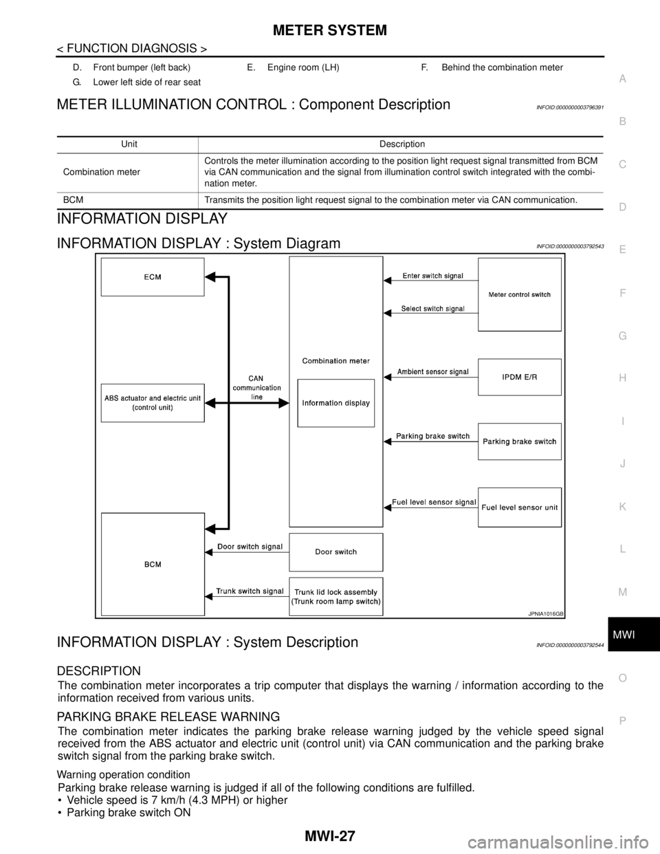
INFORMATION DISPLAY : System DiagramINFOID:0000000003792543
INFORMATION DISPLAY : System DescriptionINFOID:0000000003792544
DESCRIPTION
The combination meter incorporates a trip computer that displays the warning / information according to the
information received from various units.
PARKING BRAKE RELEASE WARNING
The combination meter indicates the parking brake release warning judged by the vehicle speed signal
received from the ABS actuator and electric unit (control unit) via CAN communication and the parking brake
switch signal from the parking brake switch.
Warning operation condition
Parking brake release warning is judged if all of the following conditions are fulfilled.
Vehicle speed is 7 km/h (4.3 MPH) or higher
Parking brake switch ON
D. Front bumper (left back) E. Engine room (LH) F. Behind the combination meter
G. Lower left side of rear seat
Unit Description
Combination meterControls the meter illumination according to the position light request signal transmitted from BCM
via CAN communication and the signal from illumination control switch integrated with the combi-
nation meter.
BCM Transmits the position light request signal to the combination meter via CAN communication.
JPNIA1016GB
Page 3283 of 5121

MWI
METER SYSTEM
MWI-29
< FUNCTION DIAGNOSIS >
C
D
E
F
G
H
I
J
K
L
MB A
O
P
NOTE:
The ambient sensor input value that is displayed on “Data Monitor” of CONSULT-III is the value before the
correction. It may not match the indicated temperature on the information display.
The ambient temperature may be indicated higher than the actual temperature, depending on heat in the
engine, the road surface temperature, and so on.
SETTING
Setting item list
* : Press and hold the switch (1 second or more).Items Setting range Setting unit Description
ALERTTIME TO REST No setting - 6 hours30 minutes,
[60 minutes]*Time to rest is displayed on the informa-
tion display if the vehicle reached the set
travel distance.
ICY ON/OFF —Low outside temp is displayed on the in-
formation display if the ambient tempera-
ture is 3°C (37°F) or less.
MAINTENANCEENGINE OIL No setting - 30,000 km500 km,
1000 km*The engine oil replacement interval is dis-
played on the information display if the ve-
hicle reached the set distance.
OIL FILTER No setting - 30,000 km500 km,
1000 km*The oil filter replacement interval is dis-
played on the information display if the ve-
hicle reached the set distance.
TIRE No setting - 30,000 km500 km,
1000 km*The tire replacement interval is displayed
on the information display if the vehicle
reached the set distance.
OTHER No setting - 30,000 km500 km,
1000 km*The other replacement interval is dis-
played on the information display if the ve-
hicle reached the set distance.
UNIT km, km/l / km, l/100km — The unit setting can be changed.
Page 3284 of 5121
MWI-30
< FUNCTION DIAGNOSIS >
METER SYSTEM
INFORMATION DISPLAY : Component Parts Location
INFOID:0000000003879664
1. ABS actuator and electric unit (con-
trol unit)2. ECM 3. TCM
4. Oil pressure switch 5. Ambient sensor 6. IPDM E/R
7. BCM 8. Combination meter 9. Fuel level sensor unit and fuel pump
A. Engine room (LH) B. Engine room (LH) C. Engine front side
JPNIA1025ZZ
Page 3285 of 5121

MWI
METER SYSTEM
MWI-31
< FUNCTION DIAGNOSIS >
C
D
E
F
G
H
I
J
K
L
MB A
O
P
INFORMATION DISPLAY : Component DescriptionINFOID:0000000003792546
D. Front bumper (left back) E. Engine room (LH) F. Behind the combination meter
G. Lower left side of rear seat
Unit Description
Combination meter Controls the information display according to the signal received from each unit.
Fuel level sensor unit Refer to MWI-45, "
Description".
ECMTransmits the following signals to the combination meter via CAN communication.
Engine speed signal
Fuel consumption monitor signal
ABS actuator and electric unit
(control unit)Transmits the vehicle speed signal to the combination meter via CAN communication.
BCM Transmits signals provided by various units to the combination meter via CAN communication.
Meter control switchTransmits the following signals to the combination meter.
Enter switch signal
Select switch signal
Parking brake switch Refer to MWI-52, "
Description".
Door switch Transmits the door switch signals to BCM.
Trunk room lamp switch Transmits the trunk room lamp switch signal to BCM
Ambient sensorDetects the ambient air temperature and transmits the ambient sensor signal to the combination
meter.