2008 NISSAN TEANA sensor
[x] Cancel search: sensorPage 2867 of 5121
![NISSAN TEANA 2008 Service Manual PRECAUTIONS
HAC-239
< PRECAUTION >[WITH 7 INCH DISPLAY]
C
D
E
F
G
H
J
K
L
MA
B
HAC
N
O
P
Explain that recovery of the contaminated refrigerant could damage service equipment and refrigerant sup-
ply NISSAN TEANA 2008 Service Manual PRECAUTIONS
HAC-239
< PRECAUTION >[WITH 7 INCH DISPLAY]
C
D
E
F
G
H
J
K
L
MA
B
HAC
N
O
P
Explain that recovery of the contaminated refrigerant could damage service equipment and refrigerant sup-
ply](/manual-img/5/57391/w960_57391-2866.png)
PRECAUTIONS
HAC-239
< PRECAUTION >[WITH 7 INCH DISPLAY]
C
D
E
F
G
H
J
K
L
MA
B
HAC
N
O
P
Explain that recovery of the contaminated refrigerant could damage service equipment and refrigerant sup-
ply.
Suggest the customer return the vehicle to the location of previous service where the contamination may
have occurred.
If repairing, recover the refrigerant using only dedicated equipment and containers. Never reintroduce
contaminated refrigerant into the existing service equipment. Contact a local refrigerant product retailer
for available service if the facility does not have dedicated recovery equipment. This refrigerant must be dis-
posed of in accordance with all federal and local regulations. In addition, replacement of all refrigerant sys-
tem components on the vehicle is recommended.
The air conditioner warranty is void if the vehicle is within the warranty period. Please contact Nissan Cus-
tomer Affairs for further assistance.
General Refrigerant PrecautionINFOID:0000000003884817
WARNING:
Never breath A/C refrigerant, lubricant vapor or mist. Exposure may irritate eyes, nose and throat.
Remove HFC-134a (R-134a) from the A/C system, using certified service equipment meeting require-
ments of SAE J-2210 [HFC-134a (R-134a) recycling equipment], or J-2209 [HFC-134a (R-134a) recov-
ery equipment]. Ventilate work area before resuming service if accidental system discharge occurs.
Additional health and safety information may be obtained from refrigerant and lubricant manufactur-
ers.
Never release refrigerant into the air. Use approved recovery/recycling equipment to capture the
refrigerant each time an air conditioning system is discharged.
Always wear eye and hand protection (goggles and gloves) when working with any refrigerant or air
conditioning system.
Never store or heat refrigerant containers above 52°C (126°F).
Never heat a refrigerant container with an open flame. Place the bottom of the container in a warm
pail of water if container warming is required.
Never intentionally drop, puncture, or incinerate refrigerant containers.
Keep refrigerant away from open flames. Poisonous gas is produced if refrigerant burns.
Refrigerant displaces oxygen, therefore be certain to work in well ventilated areas to prevent suffo-
cation.
Never pressure test or leakage test HFC-134a (R-134a) service equipment and/or vehicle air condi-
tioning systems with compressed air during repair. Some mixtures of air and HFC-134a (R-134a)
have been shown to be combustible at elevated pressures. These mixtures, if ignited, may cause
injury or property damage. Additional health and safety information may be obtained from refriger-
ant manufacturers.
Refrigerant ConnectionINFOID:0000000003884818
A new type refrigerant connection has been introduced to all refrigerant lines except the following location.
Expansion valve to evaporator
Refrigerant pressure sensor to liquid tank
O-RING AND REFRIGERANT CONNECTION
Page 2868 of 5121
![NISSAN TEANA 2008 Service Manual HA C-240
< PRECAUTION >[WITH 7 INCH DISPLAY]
PRECAUTIONS
CAUTION:
The new and former refrigerant connections use different O-ring configurations. Never confuse O-
rings since they are not interchangea NISSAN TEANA 2008 Service Manual HA C-240
< PRECAUTION >[WITH 7 INCH DISPLAY]
PRECAUTIONS
CAUTION:
The new and former refrigerant connections use different O-ring configurations. Never confuse O-
rings since they are not interchangea](/manual-img/5/57391/w960_57391-2867.png)
HA C-240
< PRECAUTION >[WITH 7 INCH DISPLAY]
PRECAUTIONS
CAUTION:
The new and former refrigerant connections use different O-ring configurations. Never confuse O-
rings since they are not interchangeable. Refrigerant may leak at the connection if a wrong O-ring is
installed.
O-Ring Part Numbers and Specifications
F. Former type refrigerant connection N. New type refrigerant connection
:O-ring size
JPIIA0453ZZ
Connection type Piping connection point Part number QTY O-ring size
NewLow-pressure flexible hose to low-pressure pipe 92474 N8210 1 19
High-pressure pipe to condenser pipe assembly (Outlet) 92471 N8210 1 8
Condenser pipe assembly (Inlet) to high-pressure flexible
hose (One-touch joint)92472 N8210 1 12
Condenser assembly to condenser pipe as-
semblyInlet 92472 N8210 1 12
Outlet 92471 N8210 1 8
Low-pressure pipe to expansion valve 92473 N8210 1 16
High-pressure pipe to expansion valve 92471 N8210 1 8
Compressor to low-pressure flexible hose 92474 N8210 1 19
Compressor to high-pressure flexible hose 92472 N8210 1 12
Liquid tank to condenser assemblyInlet
92471 N82101
8
Outlet 1
FormerRefrigerant pressure sensor to liquid tank J2476 89956 1 10
Expansion valve to evaporator pipe assemblyInlet 92475 71L00 1 12
Outlet 92475 72L00 1 16
Evaporator to evaporator pipe assemblyInlet 92475 71L00 1 12
Outlet 92475 72L00 1 16
Page 2933 of 5121

INL-54
< ECU DIAGNOSIS >
BCM (BODY CONTROL MODULE)
DOOR SW-RLRear LH door closed Off
Rear LH door opened On
DOOR SW-BKNOTE:
The item is indicated, but not monitored. Off
CDL LOCK SWOther than power door lock switch LOCK Off
Power door lock switch LOCK On
CDL UNLOCK SWOther than power door lock switch UNLOCK Off
Power door lock switch UNLOCK On
KEY CYL LK-SWNOTE:
The item is indicated, but not monitored. Off
KEY CYL UN-SWNOTE:
The item is indicated, but not monitored. Off
KEY CYL SW-TRNOTE:
The item is indicated, but not monitored. Off
HAZARD SWHazard switch is OFF Off
Hazard switch is ON On
REAR DEF SW
NOTE:
At model with BOSE au-
dio system this item is in-
dicated, but is not
monitored.Rear window defogger switch is OFF Off
Rear window defogger switch is ON On
TR CANCEL SWNOTE:
The item is indicated, but not monitored. Off
TR/BD OPEN SWTrunk lid opener switch OFF Off
While the trunk lid opener switch is turned ON On
TRNK/HAT MNTRTrunk lid closed Off
Trunk lid opened On
RKE-LOCKLOCK button of the key is not pressed Off
LOCK button of the key is pressed On
RKE-UNLOCKUNLOCK button of the key is not pressed Off
UNLOCK button of the key is pressed On
RKE-TR/BDTRUNK OPEN button of the key is not pressed Off
TRUNK OPEN button of the key is pressed On
RKE-PANICNOTE:
The item is indicated, but not monitored. Off
RKE-P/W OPENNOTE:
The item is indicated, but not monitored. Off
RKE-MODE CHGLOCK/UNLOCK button of the key is not pressed and held simulta-
neouslyOff
LOCK/UNLOCK button of the key is pressed and held simulta-
neouslyOn
OPTICAL SENSORBright outside of the vehicle Close to 5 V
Dark outside of the vehicle Close to 0 V
REQ SW -DRDriver door request switch is not pressed Off
Driver door request switch is pressed On
REQ SW -ASPassenger door request switch is not pressed Off
Passenger door request switch is pressed On Monitor Item Condition Value/Status
Page 2951 of 5121
INL-72
< ECU DIAGNOSIS >
BCM (BODY CONTROL MODULE)
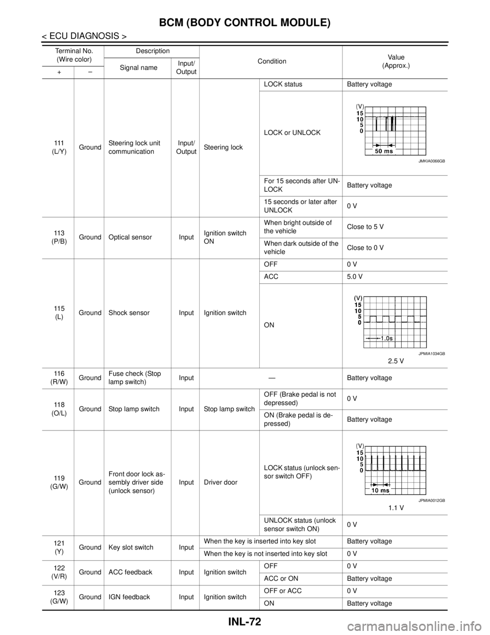
111
(L/Y)GroundSteering lock unit
communicationInput/
OutputSteering lockLOCK status Battery voltage
LOCK or UNLOCK
For 15 seconds after UN-
LOCKBattery voltage
15 seconds or later after
UNLOCK0 V
11 3
(P/B)Ground Optical sensor InputIgnition switch
ONWhen bright outside of
the vehicleClose to 5 V
When dark outside of the
vehicleClose to 0 V
11 5
(L)Ground Shock sensor Input Ignition switchOFF 0 V
ACC 5.0 V
ON
2.5 V
11 6
(R/W)GroundFuse check (Stop
lamp switch)Input — Battery voltage
11 8
(O/L)Ground Stop lamp switch Input Stop lamp switchOFF (Brake pedal is not
depressed)0 V
ON (Brake pedal is de-
pressed)Battery voltage
11 9
(G/W)GroundFront door lock as-
sembly driver side
(unlock sensor)Input Driver doorLOCK status (unlock sen-
sor switch OFF)
1.1 V
UNLOCK status (unlock
sensor switch ON)0 V
121
(Y)Ground Key slot switch InputWhen the key is inserted into key slot Battery voltage
When the key is not inserted into key slot 0 V
122
(V/R)Ground ACC feedback Input Ignition switchOFF 0 V
ACC or ON Battery voltage
123
(G/W)Ground IGN feedback Input Ignition switchOFF or ACC 0 V
ON Battery voltage Te r m i n a l N o .
(Wire color)Description
ConditionVa l u e
(Approx.)
Signal nameInput/
Output +–
JMKIA0066GB
JPMIA1034GB
JPMIA0012GB
Page 3025 of 5121
INT-48
< ON-VEHICLE REPAIR >
FLOOR TRIM
6. Remove instrument lower cover, instrument driver panel, instrument assist lower panel and instrument
side panel (LH/RH). Refer to IP-12, "
Removal and Installation".
7. Remove G-sensor. Refer to VTL-82, "
WITH INTELLIGENT AIR CONDITIONER SYSTEM : Removal and
Installation".
8. Remove diagnosis sensor unit. Refer to SR-22, "
Removal and Installation".
9. Remove dash side finisher (LH/RH), front kicking plate inner (LH/RH), center pillar lower garnish (LH/RH)
and body side welt (LH/RH). Refer to INT-39, "
Removal and Installation".
10. Remove side brake wire. Refer to BR-17, "
Removal and Installation".
11. Remove automatic transmission drive. Refer to FAX-16, "
Exploded View".
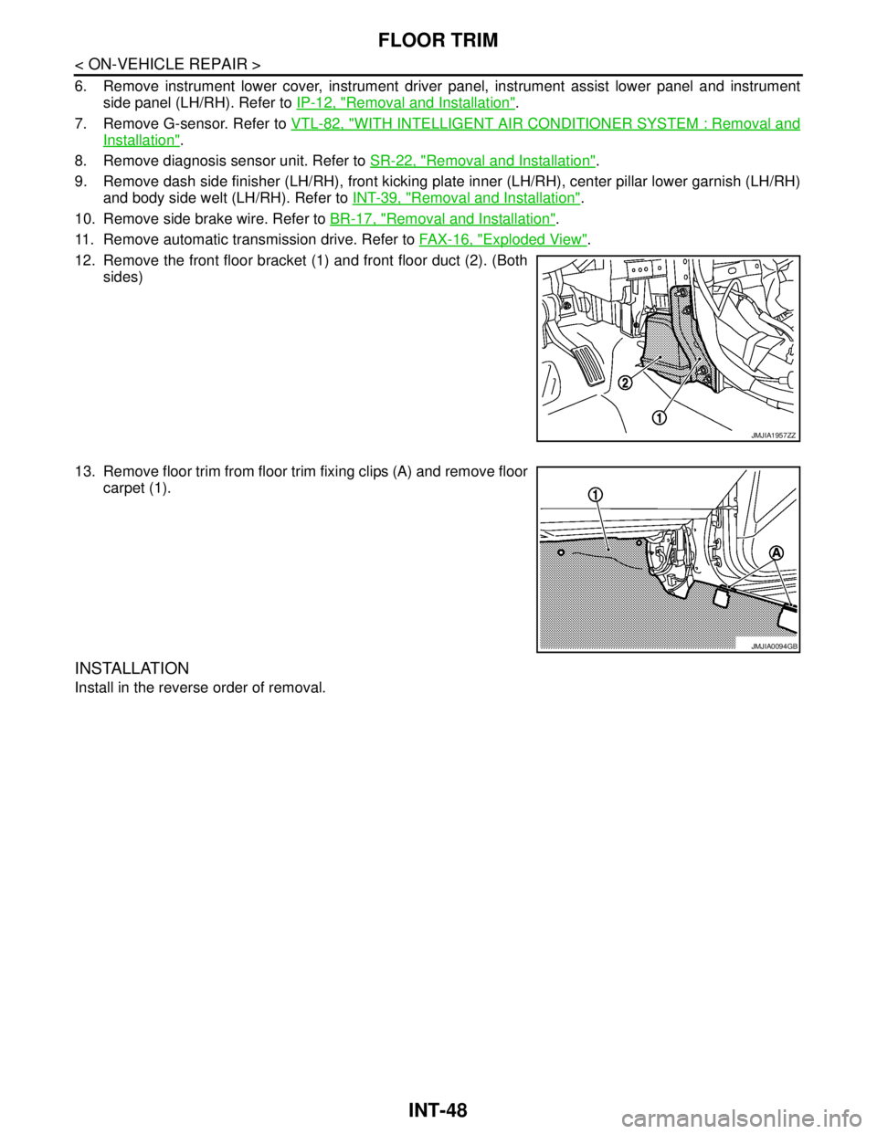
12. Remove the front floor bracket (1) and front floor duct (2). (Both
sides)
13. Remove floor trim from floor trim fixing clips (A) and remove floor
carpet (1).
INSTALLATION
Install in the reverse order of removal.
JMJIA1957ZZ
JMJIA0094GB
Page 3052 of 5121
IP-12
< ON-VEHICLE REPAIR >
INSTRUMENT PANEL ASSEMBLY
Removal and Installation
INFOID:0000000003816778
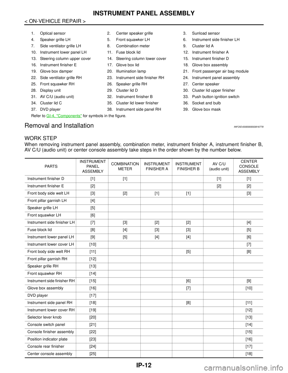
WORK STEP
When removing instrument panel assembly, combination meter, instrument finisher A, instrument finisher B,
AV C/U (audio unit) or center console assembly take steps in the order shown by the number below.
1. Optical sensor 2. Center speaker grille 3. Sunload sensor
4. Speaker grille LH 5. Front squawker LH 6. Instrument side finisher LH
7. Side ventilator grille LH 8. Combination meter 9. Cluster lid A
10. Instrument lower panel LH 11. Fuse block lid 12. Instrument finisher A
13. Steering column upper cover 14. Steering column lower cover 15. Instrument finisher D
16. Instrument finisher E 17. Glove box lid 18. Glove box assembly
19. Glove box damper 20. Illumination lamp 21. Front passenger air bag module
22. Side ventilator grille RH 23. Instrument side finisher RH 24. Instrument panel assembly
25. Front squawker RH 26. Speaker grille RH 27. Center speaker
28. Display unit 29. Cluster lid D 30. Cluster lid upper finisher
31. AV C/U (audio unit) 32. Instrument finisher B 33. Push button ignition switch
34. Cluster lid C 35. Cluster lid lower finisher 36. Socket and bulb
37. DVD player 38. Instrument side panel RH 39. Glove box mask
Refer to GI-4, "
Components" for symbols in the figure.
PA R T SINSTRUMENT
PA N E L
ASSEMBLYCOMBINATION
METERINSTRUMENT
FINISHER AINSTRUMENT
FINISHER BAV C / U
(audio unit)CENTER
CONSOLE
ASSEMBLY
Instrument finisher D [1] [1] [1] [1]
Instrument finisher E [2] [2] [2]
Front body side welt LH [3] [2] [1] [1] [3]
Front pillar garnish LH [4]
Speaker grille LH [5]
Front squawker LH [6]
Instrument side finisher LH [7] [3] [2] [2] [4]
Fuse block lid [8] [4] [3] [3] [5]
Instrument lower panel LH [9] [5] [4] [4] [6]
Instrument lower cover LH [10][7]
Front body side welt RH [11] [5] [8]
Front pillar garnish RH [12]
Speaker grille RH [13]
Front squawker RH [14]
Instrument side finisher RH [15] [6] [9]
Glove box assembly [16] [7] [10]
DVD player [17]
Instrument side panel RH [18] [8] [11]
Instrument lower cover RH [19][12]
Selector lever knob [20][13]
Console switch panel [21][14]
Console finisher assembly [22][15]
Position indicator plate [23][16]
Console rear finisher [24][17]
Center console assembly [25][18]
Page 3054 of 5121
IP-14
< ON-VEHICLE REPAIR >
INSTRUMENT PANEL ASSEMBLY
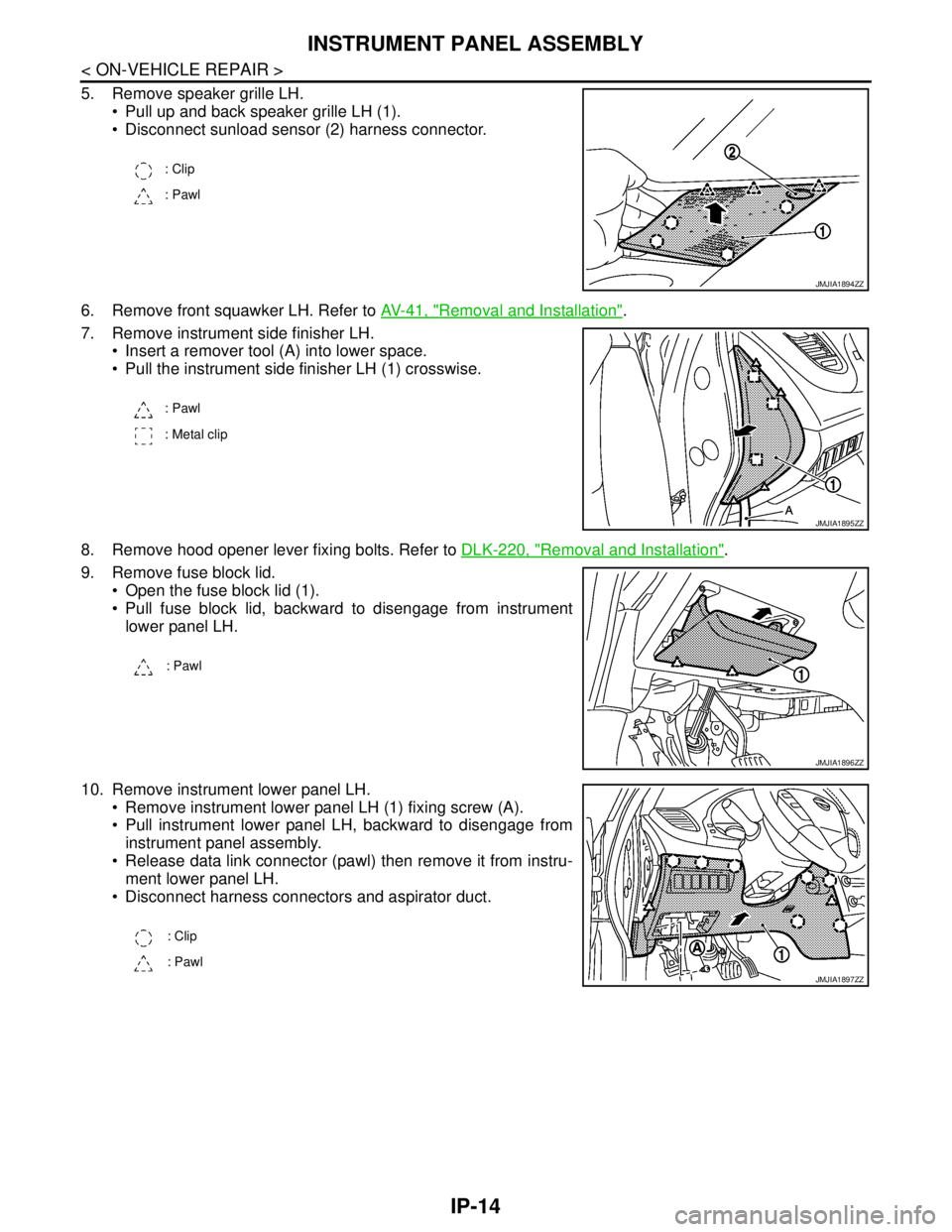
5. Remove speaker grille LH.
Pull up and back speaker grille LH (1).
Disconnect sunload sensor (2) harness connector.
6. Remove front squawker LH. Refer to AV-41, "
Removal and Installation".
7. Remove instrument side finisher LH.
Insert a remover tool (A) into lower space.
Pull the instrument side finisher LH (1) crosswise.
8. Remove hood opener lever fixing bolts. Refer to DLK-220, "
Removal and Installation".
9. Remove fuse block lid.
Open the fuse block lid (1).
Pull fuse block lid, backward to disengage from instrument
lower panel LH.
10. Remove instrument lower panel LH.
Remove instrument lower panel LH (1) fixing screw (A).
Pull instrument lower panel LH, backward to disengage from
instrument panel assembly.
Release data link connector (pawl) then remove it from instru-
ment lower panel LH.
Disconnect harness connectors and aspirator duct.
: Clip
: Pawl
JMJIA1894ZZ
: Pawl
: Metal clip
JMJIA1895ZZ
: Pawl
JMJIA1896ZZ
: Clip
: Pawl
JMJIA1897ZZ
Page 3055 of 5121
INSTRUMENT PANEL ASSEMBLY
IP-15
< ON-VEHICLE REPAIR >
C
D
E
F
G
H
I
K
L
MA
B
IP
N
O
P
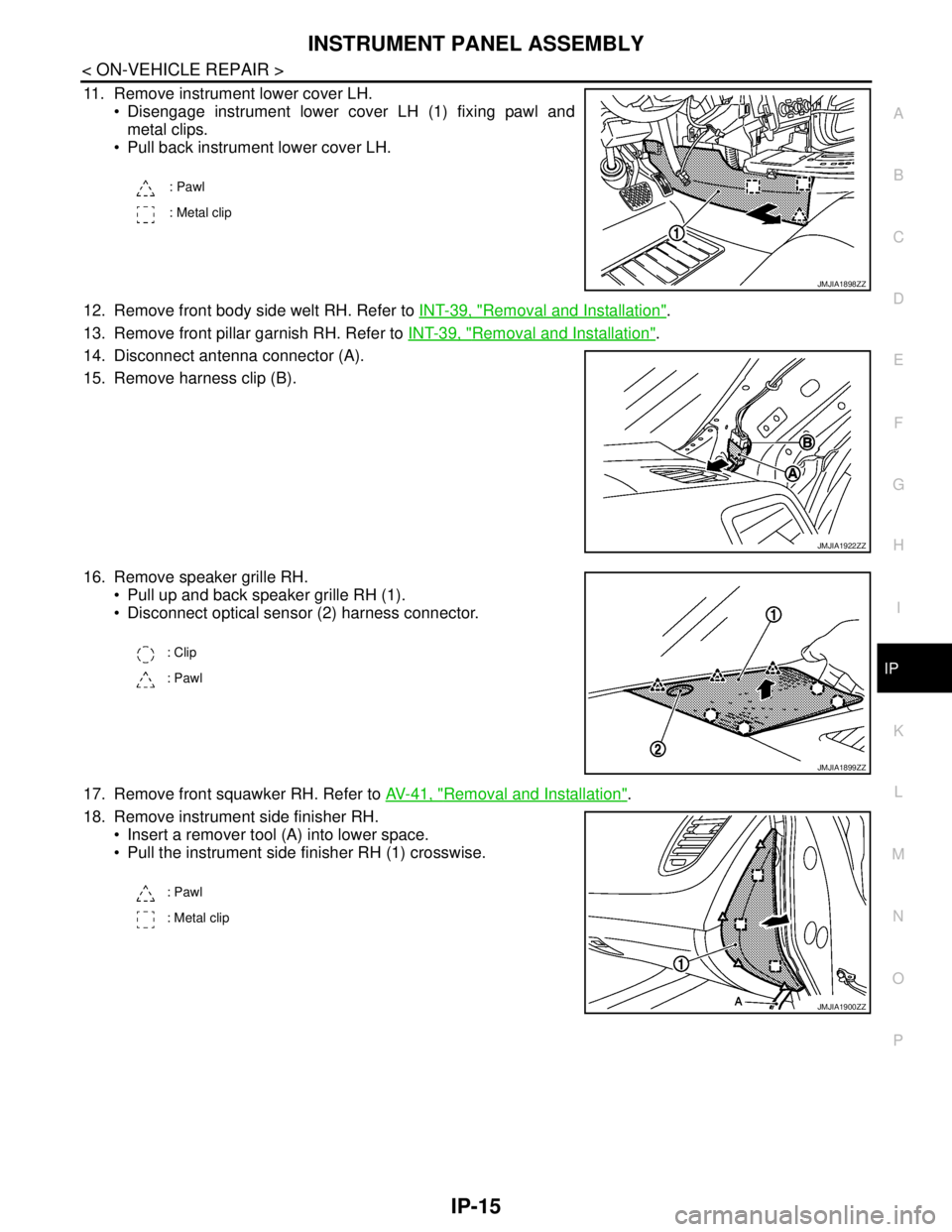
11. Remove instrument lower cover LH.
Disengage instrument lower cover LH (1) fixing pawl and
metal clips.
Pull back instrument lower cover LH.
12. Remove front body side welt RH. Refer to INT-39, "
Removal and Installation".
13. Remove front pillar garnish RH. Refer to INT-39, "
Removal and Installation".
14. Disconnect antenna connector (A).
15. Remove harness clip (B).
16. Remove speaker grille RH.
Pull up and back speaker grille RH (1).
Disconnect optical sensor (2) harness connector.
17. Remove front squawker RH. Refer to AV-41, "
Removal and Installation".
18. Remove instrument side finisher RH.
Insert a remover tool (A) into lower space.
Pull the instrument side finisher RH (1) crosswise.
: Pawl
: Metal clip
JMJIA1898ZZ
JMJIA1922ZZ
: Clip
: Pawl
JMJIA1899ZZ
: Pawl
: Metal clip
JMJIA1900ZZ