Page 1913 of 5121

EM-38
< ON-VEHICLE REPAIR >
OIL PAN AND OIL STRAINER
OIL PAN AND OIL STRAINER
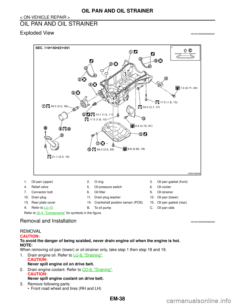
Exploded ViewINFOID:0000000003802261
Removal and InstallationINFOID:0000000003802262
REMOVAL
CAUTION:
To avoid the danger of being scalded, never drain engine oil when the engine is hot.
NOTE:
When removing oil pan (lower) or oil strainer only, take step 1 then step 18 and 19.
1. Drain engine oil. Refer to LU-8, "
Draining".
CAUTION:
Never spill engine oil on drive belt.
2. Drain engine coolant. Refer to CO-8, "
Draining".
CAUTION:
Never spill engine coolant on drive belt.
3. Remove following parts:
Front road wheel and tires (RH and LH)
1. Oil pan (upper) 2. O-ring 3. Oil pan gasket (front)
4. Relief valve 5. Oil pressure switch 6. Oil cooler
7. Connector bolt 8. Oil filter 9. Oil strainer
10. Drain plug 11. Drain plug washer 12. Oil pan (lower)
13. Rear plate cover 14. Crankshaft position sensor (POS) 15. Oil pan gasket (rear)
A. Refer to LU-10
B. To oil pump C. Oil pan side
Refer to GI-4, "
Components" for symbols in the figure.
JPBIA1636GB
Page 1917 of 5121

EM-42
< ON-VEHICLE REPAIR >
OIL PAN AND OIL STRAINER
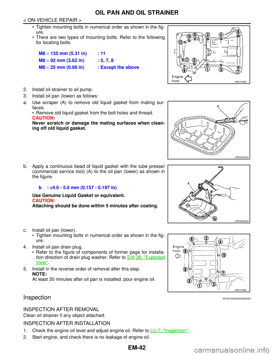
Tighten mounting bolts in numerical order as shown in the fig-
ure.
There are two types of mounting bolts. Refer to the following
for locating bolts.
2. Install oil strainer to oil pump.
3. Install oil pan (lower) as follows:
a. Use scraper (A) to remove old liquid gasket from mating sur-
faces.
Remove old liquid gasket from the bolt holes and thread.
CAUTION:
Never scratch or damage the mating surfaces when clean-
ing off old liquid gasket.
b. Apply a continuous bead of liquid gasket with the tube presser
(commercial service tool) (A) to the oil pan (lower) as shown in
the figure.
Use Genuine Liquid Gasket or equivalent.
CAUTION:
Attaching should be done within 5 minutes after coating.
c. Install oil pan (lower).
Tighten mounting bolts in numerical order as shown in the fig-
ure.
4. Install oil pan drain plug.
Refer to the figure of components of former page for installa-
tion direction of drain plug washer. Refer to EM-38, "
Exploded
View".
5. Install in the reverse order of removal after this step.
NOTE:
At least 30 minutes after oil pan is installed, pour engine oil.
InspectionINFOID:0000000003802263
INSPECTION AFTER REMOVAL
Clean oil strainer if any object attached.
INSPECTION AFTER INSTALLATION
1. Check the engine oil level and adjust engine oil. Refer to LU-7, "Inspection".
2. Start engine, and check there is no leakage of engine oil.M8 × 135 mm (5.31 in) : 11
M8 × 92 mm (3.62 in) : 5, 7, 8
M8 × 25 mm (0.98 in) : Except the above
PBIC1636E
JPBIA0025ZZ
b: φ4.0 - 5.0 mm (0.157 - 0.197 in)
JPBIA0026ZZ
PBIC0782E
Page 1959 of 5121
EM-84
< DISASSEMBLY AND ASSEMBLY >
CAMSHAFT
CAMSHAFT
Exploded ViewINFOID:0000000003802283
Removal and InstallationINFOID:0000000003802284
REMOVAL
1. Remove front timing chain case, camshaft sprocket, timing chain and rear timing chain case. Refer to EM-
52, "Exploded View" and EM-79, "Exploded View".
1. Camshaft bracket (No. 3, 4) 2. Camshaft bracket (No. 2) 3. Seal washer
4. Camshaft bracket (No. 1) 5. Dowel pin 6. Camshaft (EXH) (bank 1)
7. Camshaft (INT) (bank 1) 8. Valve lifter 9.Timing chain tensioner (secondary)
(bank 1)
10. Spring 11. Plunger 12.Timing chain tensioner (secondary)
(bank 2)
13. Cylinder head (bank 2) 14. Dowel pin 15. Camshaft sensor bracket
16. Camshaft (EXH) 17. Camshaft signal plate (INT) 18. Camshaft (INT)
19. Cylinder head (bank 1) 20. Camshaft signal plate (INT) 21. Camshaft sensor bracket
A. Refer to EM-84
Refer to GI-4, "Components" for symbols in the figure.
JPBIA1719GB
Page 1988 of 5121

CYLINDER BLOCK
EM-113
< DISASSEMBLY AND ASSEMBLY >
C
D
E
F
G
H
I
J
K
L
MA
EM
N
P O
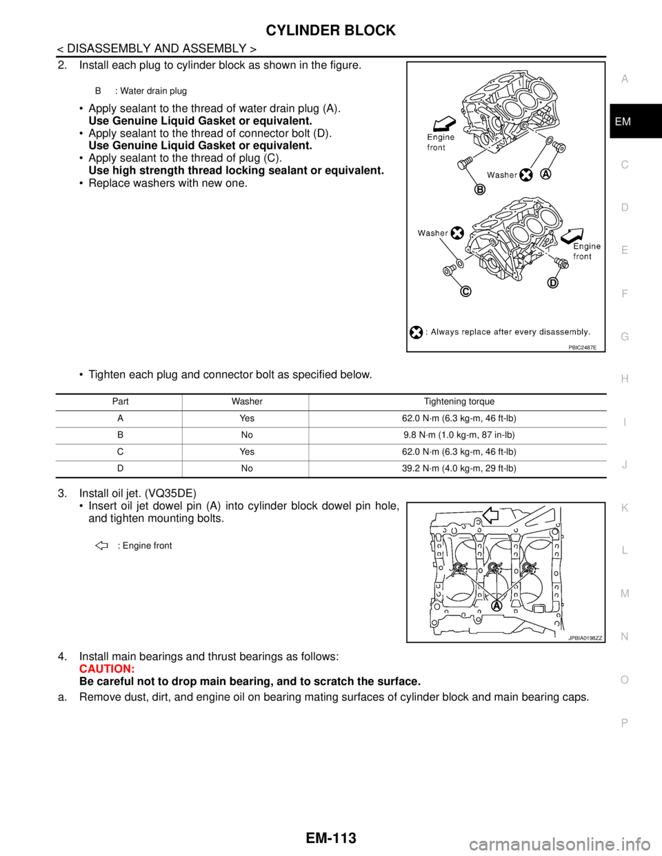
2. Install each plug to cylinder block as shown in the figure.
Apply sealant to the thread of water drain plug (A).
Use Genuine Liquid Gasket or equivalent.
Apply sealant to the thread of connector bolt (D).
Use Genuine Liquid Gasket or equivalent.
Apply sealant to the thread of plug (C).
Use high strength thread locking sealant or equivalent.
Replace washers with new one.
Tighten each plug and connector bolt as specified below.
3. Install oil jet. (VQ35DE)
Insert oil jet dowel pin (A) into cylinder block dowel pin hole,
and tighten mounting bolts.
4. Install main bearings and thrust bearings as follows:
CAUTION:
Be careful not to drop main bearing, and to scratch the surface.
a. Remove dust, dirt, and engine oil on bearing mating surfaces of cylinder block and main bearing caps.
B : Water drain plug
PBIC2487E
Part Washer Tightening torque
A Yes 62.0 N·m (6.3 kg-m, 46 ft-lb)
B No 9.8 N·m (1.0 kg-m, 87 in-lb)
C Yes 62.0 N·m (6.3 kg-m, 46 ft-lb)
D No 39.2 N·m (4.0 kg-m, 29 ft-lb)
: Engine front
JPBIA0198ZZ
Page 2056 of 5121
![NISSAN TEANA 2008 Service Manual DIAGNOSIS SYSTEM (BCM)
EXL-27
< FUNCTION DIAGNOSIS >[XENON TYPE]
C
D
E
F
G
H
I
J
K
MA
B
EXL
N
O
P
DIAGNOSIS SYSTEM (BCM)
COMMON ITEM
COMMON ITEM : CONSULT-III Function (BCM - COMMON ITEM)INFOID:000000 NISSAN TEANA 2008 Service Manual DIAGNOSIS SYSTEM (BCM)
EXL-27
< FUNCTION DIAGNOSIS >[XENON TYPE]
C
D
E
F
G
H
I
J
K
MA
B
EXL
N
O
P
DIAGNOSIS SYSTEM (BCM)
COMMON ITEM
COMMON ITEM : CONSULT-III Function (BCM - COMMON ITEM)INFOID:000000](/manual-img/5/57391/w960_57391-2055.png)
DIAGNOSIS SYSTEM (BCM)
EXL-27
< FUNCTION DIAGNOSIS >[XENON TYPE]
C
D
E
F
G
H
I
J
K
MA
B
EXL
N
O
P
DIAGNOSIS SYSTEM (BCM)
COMMON ITEM
COMMON ITEM : CONSULT-III Function (BCM - COMMON ITEM)INFOID:0000000003894258
APPLICATION ITEM
CONSULT-III performs the following functions via CAN communication with BCM.
SYSTEM APPLICATION
BCM can perform the following functions for each system.
NOTE:
It can perform the diagnosis modes except the following for all sub system selection items.
×: Applicable item
NOTE:
*: This item is displayed, but is not used.
FREEZE FRAME DATA (FFD) AND IGN COUNTER
Freeze Frame Data
Diagnosis mode Function Description
Work Support Changes the setting for each system function.
Self Diagnostic Result Displays the diagnosis results judged by BCM.
CAN Diag Support MonitorMonitors the reception status of CAN communication viewed from BCM. Refer to CONSULT-III opera-
tion manual.
Data Monitor The BCM input/output signals are displayed.
Active Test The signals used to activate each device are forcibly supplied from BCM.
Ecu Identification The BCM part number is displayed.
Configuration Read and save the vehicle specification.
Write the vehicle specification when replacing BCM.
System Sub system selection itemDiagnosis mode
Work Support Data Monitor Active Test
Door lock DOOR LOCK×××
Rear window defogger REAR DEFOGGER××
Warning chime BUZZER××
Interior room lamp timer INT LAMP×××
Exterior lamp HEAD LAMP×××
Wiper and washer WIPER×××
Turn signal and hazard warning lamps FLASHER×××
— AIR CONDITONER*
Intelligent Key system
Engine start systemINTELLIGENT KEY×××
Combination switch COMB SW×
Body control system BCM×
NVIS - NATS IMMU××
Interior room lamp battery saver BATTERY SAVER×××
Trunk lid opener system TRUNK××
Vehicle security system THEFT ALM×××
— RETAINED PWR*×
Signal buffer system SIGNAL BUFFER××
— TPMS (AIR PRESSURE MONITOR)*×××
Page 2064 of 5121
![NISSAN TEANA 2008 Service Manual DIAGNOSIS SYSTEM (IPDM E/R)
EXL-35
< FUNCTION DIAGNOSIS >[XENON TYPE]
C
D
E
F
G
H
I
J
K
MA
B
EXL
N
O
PACTIVE TEST
Te s t i t e m
IGN RLY
[Off/On]×Displays the status of the ignition relay judged by NISSAN TEANA 2008 Service Manual DIAGNOSIS SYSTEM (IPDM E/R)
EXL-35
< FUNCTION DIAGNOSIS >[XENON TYPE]
C
D
E
F
G
H
I
J
K
MA
B
EXL
N
O
PACTIVE TEST
Te s t i t e m
IGN RLY
[Off/On]×Displays the status of the ignition relay judged by](/manual-img/5/57391/w960_57391-2063.png)
DIAGNOSIS SYSTEM (IPDM E/R)
EXL-35
< FUNCTION DIAGNOSIS >[XENON TYPE]
C
D
E
F
G
H
I
J
K
MA
B
EXL
N
O
PACTIVE TEST
Te s t i t e m
IGN RLY
[Off/On]×Displays the status of the ignition relay judged by IPDM E/R.
PUSH SW
[Off/On]Displays the status of the push-button ignition switch judged by IPDM E/R.
INTER/NP SW
[Off/On]Displays the status of the shift position judged by IPDM E/R.
ST RLY CONT
[Off/On]Displays the status of the starter relay status signal received from BCM via CAN
communication.
IHBT RLY -REQ
[Off/On]Displays the status of the starter control relay signal received from BCM via CAN
communication.
ST/INHI RLY
[Off/ ST /INHI/UNKWN]Displays the status of the starter relay and starter control relay judged by IPDM
E/R.
DETENT SW
[Off/On]Displays the status of the control device (detention switch) judged by IPDM E/R.
S/L RLY -REQ
[Off/On]Displays the status of the steering lock relay signal received from BCM via CAN
communication.
S/L STATE
[LOCK/UNLOCK/UNKWN]Displays the status of the steering lock judged by IPDM E/R.
DTRL REQ
[Off]NOTE:
The item is indicated, but not monitored.
OIL P SW
[Open/Close]Displays the status of the oil pressure switch judged by IPDM E/R.
HOOD SW
[Off/On]Displays the status of the hood switch judged by IPDM E/R.
HL WASHER REQ
[Off]Display the status of the headlamp washer request signal received from BCM via
CAN communication.
THFT HRN REQ
[Off/On]Displays the status of the theft warning horn request signal received from BCM
via CAN communication.
HORN CHIRP
[Off/On]Displays the status of the horn reminder signal received from BCM via CAN com-
munication.
CRNRNG LMP REQ
[Off]NOTE:
The item is indicated, but not monitored. Monitor Item
[Unit]MAIN SIG-
NALSDescription
Test item Operation Description
CORNERING LAMPOff
NOTE:
The item is indicated, but cannot be tested. LH
RH
HORN On Operates horn relay for 20 ms.
FRONT WIPEROff OFF
Lo Operates the front wiper relay.
Hi Operates the front wiper relay and front wiper high relay.
MOTOR FAN1OFF
2 Operates the cooling fan relay-1.
3 Operates the cooling fan relay-2.
4 Operates the cooling fan relay-2 and cooling fan relay-3.
HEAD LAMP WASHER On Operates the headlamp washer relay for 1 s.
Page 2137 of 5121
![NISSAN TEANA 2008 Service Manual EXL-108
< ECU DIAGNOSIS >[XENON TYPE]
BCM (BODY CONTROL MODULE)
ECU DIAGNOSIS
BCM (BODY CONTROL MODULE)
Reference ValueINFOID:0000000003959690
VALUES ON THE DIAGNOSIS TOOL
CONSULT-III MONITOR ITEM
Mon NISSAN TEANA 2008 Service Manual EXL-108
< ECU DIAGNOSIS >[XENON TYPE]
BCM (BODY CONTROL MODULE)
ECU DIAGNOSIS
BCM (BODY CONTROL MODULE)
Reference ValueINFOID:0000000003959690
VALUES ON THE DIAGNOSIS TOOL
CONSULT-III MONITOR ITEM
Mon](/manual-img/5/57391/w960_57391-2136.png)
EXL-108
< ECU DIAGNOSIS >[XENON TYPE]
BCM (BODY CONTROL MODULE)
ECU DIAGNOSIS
BCM (BODY CONTROL MODULE)
Reference ValueINFOID:0000000003959690
VALUES ON THE DIAGNOSIS TOOL
CONSULT-III MONITOR ITEM
Monitor Item Condition Value/Status
FR WIPER HIOther than front wiper switch HI Off
Front wiper switch HI On
FR WIPER LOWOther than front wiper switch LO Off
Front wiper switch LO On
FR WASHER SWFront washer switch OFF Off
Front washer switch ON On
FR WIPER INTOther than front wiper switch INT Off
Front wiper switch INT On
FR WIPER STOPFront wiper is not in STOP position Off
Front wiper is in STOP position On
INT VOLUME Wiper intermittent dial is in a dial position 1 - 7 Wiper intermittent dial position
TURN SIGNAL ROther than turn signal switch RH Off
Turn signal switch RH On
TURN SIGNAL LOther than turn signal switch LH Off
Turn signal switch LH On
TAIL LAMP SWOther than lighting switch 1ST and 2ND Off
Lighting switch 1ST or 2ND On
HI BEAM SWOther than lighting switch HI Off
Lighting switch HI On
HEAD LAMP SW 1Other than lighting switch 2ND Off
Lighting switch 2ND On
HEAD LAMP SW 2Other than lighting switch 2ND Off
Lighting switch 2ND On
PASSING SWOther than lighting switch PASS Off
Lighting switch PASS On
AUTO LIGHT SWOther than lighting switch AUTO Off
Lighting switch AUTO On
FR FOG SWFront fog lamp switch OFF Off
Front fog lamp switch ON On
RR FOG SWRear fog lamp switch OFF Off
Rear fog lamp switch ON On
DOOR SW-DRDriver door closed Off
Driver door opened On
DOOR SW-ASPassenger door closed Off
Passenger door opened On
DOOR SW-RRRear RH door closed Off
Rear RH door opened On
Page 2153 of 5121
EXL-124
< ECU DIAGNOSIS >[XENON TYPE]
BCM (BODY CONTROL MODULE)
107
(R/W)GroundCombination switch
INPUT 1InputCombination
switch
(Wiper intermit-
tent dial 4)All switch OFF
1.4 V
Turn signal switch LH
1.3 V
Turn signal switch RH
1.3 V
Front wiper switch LO
1.3 V
Front washer switch ON
1.3 V Te r m i n a l N o .
(Wire color)Description
ConditionVa l u e
(Approx.)
Signal nameInput/
Output +–
JPMIA0041GB
JPMIA0037GB
JPMIA0036GB
JPMIA0038GB
JPMIA0039GB