2008 NISSAN TEANA oil temperature
[x] Cancel search: oil temperaturePage 1862 of 5121
![NISSAN TEANA 2008 Service Manual ENGINE CONTROL SYSTEM SYMPTOMS
EC-401
< SYMPTOM DIAGNOSIS >[VQ25DE, VQ35DE]
C
D
E
F
G
H
I
J
K
L
MA
EC
N
P O
1 - 6: The numbers refer to the order of inspection.
(continued on the next figure)
SYSTEM â](/manual-img/5/57391/w960_57391-1861.png "NISSAN TEANA 2008 Service Manual ENGINE CONTROL SYSTEM SYMPTOMS
EC-401
< SYMPTOM DIAGNOSIS >[VQ25DE, VQ35DE]
C
D
E
F
G
H
I
J
K
L
MA
EC
N
P O
1 - 6: The numbers refer to the order of inspection.
(continued on the next figure)
SYSTEM â")
ENGINE CONTROL SYSTEM SYMPTOMS
EC-401
< SYMPTOM DIAGNOSIS >[VQ25DE, VQ35DE]
C
D
E
F
G
H
I
J
K
L
MA
EC
N
P O
1 - 6: The numbers refer to the order of inspection.
(continued on the next figure)
SYSTEM — ENGINE MECHANICAL & OTHER
Crankshaft position sensor (POS) circuit 2 2EC-218
Camshaft position sensor (PHASE) circuit 3 2EC-222
Vehicle speed signal circuit 2 3 3 3EC-234
Power steering pressure sensor circuit 2 3 3EC-236
ECM 22333333333EC-238,
EC-240
Intake valve timing control solenoid valve cir-
cuit32 13223 3EC-146
PNP signal circuit 3 3 3 3 3EC-245
VIAS control solenoid valve 1 circuit 1EC-285
VIAS control solenoid valve 2 circuit 1EC-288
Refrigerant pressure sensor circuit 2 3 3 4EC-348
Electrical load signal circuit 3EC-329
Air conditioner circuit 223333333 3 2HAC-159
ABS actuator and electric unit (control unit) 4BRC-80
SYMPTOM
Reference
page
HARD/NO START/RESTART (EXCP. HA)
ENGINE STALL
HESITATION/SURGING/FLAT SPOT
SPARK KNOCK/DETONATION
LACK OF POWER/POOR ACCELERATION
HIGH IDLE/LOW IDLE
ROUGH IDLE/HUNTING
IDLING VIBRATION
SLOW/NO RETURN TO IDLE
OVERHEATS/WATER TEMPERATURE HIGH
EXCESSIVE FUEL CONSUMPTION
EXCESSIVE OIL CONSUMPTION
BATTERY DEAD (UNDER CHARGE)
Warranty symptom code AA AB AC AD AE AF AG AH AJ AK AL AM HA
Page 1863 of 5121
![NISSAN TEANA 2008 Service Manual EC-402
< SYMPTOM DIAGNOSIS >[VQ25DE, VQ35DE]
ENGINE CONTROL SYSTEM SYMPTOMS
SYMPTOM
Reference
page
HARD/NO START/RESTART (EXCP. HA)
ENGINE STALL
HESITATION/SURGING/FLAT SPOT
SPARK KNOCK/DETONATION
LA](/manual-img/5/57391/w960_57391-1862.png "NISSAN TEANA 2008 Service Manual EC-402
< SYMPTOM DIAGNOSIS >[VQ25DE, VQ35DE]
ENGINE CONTROL SYSTEM SYMPTOMS
SYMPTOM
Reference
page
HARD/NO START/RESTART (EXCP. HA)
ENGINE STALL
HESITATION/SURGING/FLAT SPOT
SPARK KNOCK/DETONATION
LA")
EC-402
< SYMPTOM DIAGNOSIS >[VQ25DE, VQ35DE]
ENGINE CONTROL SYSTEM SYMPTOMS
SYMPTOM
Reference
page
HARD/NO START/RESTART (EXCP. HA)
ENGINE STALL
HESITATION/SURGING/FLAT SPOT
SPARK KNOCK/DETONATION
LACK OF POWER/POOR ACCELERATION
HIGH IDLE/LOW IDLE
ROUGH IDLE/HUNTING
IDLING VIBRATION
SLOW/NO RETURN TO IDLE
OVERHEATS/WATER TEMPERATURE HIGH
EXCESSIVE FUEL CONSUMPTION
EXCESSIVE OIL CONSUMPTION
BATTERY DEAD (UNDER CHARGE)
Warranty symptom code AA AB AC AD AE AF AG AH AJ AK AL AM HA
Fuel Fuel tank
5
5FL-9
Fuel piping 5 5 5 5 5 5FL-4
Va p o r l o c k—
Valve deposit
5 555 55 5—
Poor fuel (Heavy weight gasoline,
Low octane)—
Air Air duct
55555 5EM-26
Air cleanerEM-26
Air leakage from air duct
(Mass air flow sensor — electric
throttle control actuator)
5555EM-26
Electric throttle control actuatorEM-29
Air leakage from intake manifold/
Collector/GasketEM-29,
EM-32
Cranking Battery
111111
11PG-109
Generator circuitCHG-20
Starter circuit 3STR-5,
STR-6
Signal plate 6EM-104
PNP signal 4TM-48,
TM-214
Engine Cylinder head
55555 55 5EM-97
Cylinder head gasket 4 3
Cylinder block
66666 66 64
EM-110
Piston
Piston ring
Connecting rod
Bearing
Crankshaft
Page 1864 of 5121
![NISSAN TEANA 2008 Service Manual ENGINE CONTROL SYSTEM SYMPTOMS
EC-403
< SYMPTOM DIAGNOSIS >[VQ25DE, VQ35DE]
C
D
E
F
G
H
I
J
K
L
MA
EC
N
P O
1 - 6: The numbers refer to the order of inspection.Va l v e
mecha-
nismTiming chain
55555](/manual-img/5/57391/w960_57391-1863.png "NISSAN TEANA 2008 Service Manual ENGINE CONTROL SYSTEM SYMPTOMS
EC-403
< SYMPTOM DIAGNOSIS >[VQ25DE, VQ35DE]
C
D
E
F
G
H
I
J
K
L
MA
EC
N
P O
1 - 6: The numbers refer to the order of inspection.Va l v e
mecha-
nismTiming chain
55555")
ENGINE CONTROL SYSTEM SYMPTOMS
EC-403
< SYMPTOM DIAGNOSIS >[VQ25DE, VQ35DE]
C
D
E
F
G
H
I
J
K
L
MA
EC
N
P O
1 - 6: The numbers refer to the order of inspection.Va l v e
mecha-
nismTiming chain
55555 55 5EM-65
CamshaftEM-84
Intake valve timing controlEM-65
Intake valve
3EM-97
Exhaust valve
Exhaust Exhaust manifold/Tube/Muffler/
Gasket
55555 55 5EM-34
, EX-
4Three way catalyst
Lubrica-
tionOil pan/Oil strainer/Oil pump/Oil
filter/Oil gallery/Oil cooler
55555 55 5LU-7
, LU-
10, LU-11,
LU-13
Oil level (Low)/Filthy oilLU-7
Cooling
Radiator/Hose/Radiator filler cap
55555 55 45CO-12,
CO-12
Thermostat 5CO-23
Water pumpCO-18
Water galleryCO-2
Cooling fan
5CO-16
Coolant level (Low)/Contaminat-
ed coolantCO-8
NVIS (NISSAN Vehicle Immobilizer System —
NATS)11SEC-14
SYMPTOM
Reference
page
HARD/NO START/RESTART (EXCP. HA)
ENGINE STALL
HESITATION/SURGING/FLAT SPOT
SPARK KNOCK/DETONATION
LACK OF POWER/POOR ACCELERATION
HIGH IDLE/LOW IDLE
ROUGH IDLE/HUNTING
IDLING VIBRATION
SLOW/NO RETURN TO IDLE
OVERHEATS/WATER TEMPERATURE HIGH
EXCESSIVE FUEL CONSUMPTION
EXCESSIVE OIL CONSUMPTION
BATTERY DEAD (UNDER CHARGE)
Warranty symptom code AA AB AC AD AE AF AG AH AJ AK AL AM HA
Page 2528 of 5121
SERVICE INFORMATION FOR ELECTRICAL INCIDENT
GI-35
< BASIC INSPECTION >
C
D
E
F
G
H
I
J
K
L
MB
GI
N
O
P
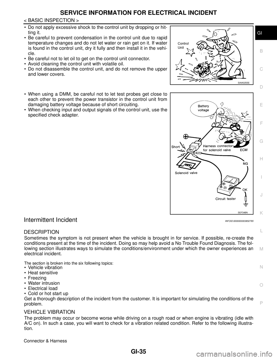
Do not apply excessive shock to the control unit by dropping or hit-
ting it.
Be careful to prevent condensation in the control unit due to rapid
temperature changes and do not let water or rain get on it. If water
is found in the control unit, dry it fully and then install it in the vehi-
cle.
Be careful not to let oil to get on the control unit connector.
Avoid cleaning the control unit with volatile oil.
Do not disassemble the control unit, and do not remove the upper
and lower covers.
When using a DMM, be careful not to let test probes get close to
each other to prevent the power transistor in the control unit from
damaging battery voltage because of short circuiting.
When checking input and output signals of the control unit, use the
specified check adapter.
Intermittent IncidentINFOID:0000000003852795
DESCRIPTION
Sometimes the symptom is not present when the vehicle is brought in for service. If possible, re-create the
conditions present at the time of the incident. Doing so may help avoid a No Trouble Found Diagnosis. The fol-
lowing section illustrates ways to simulate the conditions/environment under which the owner experiences an
electrical incident.
The section is broken into the six following topics: Vehicle vibration
Heat sensitive
Freezing
Water intrusion
Electrical load
Cold or hot start up
Get a thorough description of the incident from the customer. It is important for simulating the conditions of the
problem.
VEHICLE VIBRATION
The problem may occur or become worse while driving on a rough road or when engine is vibrating (idle with
A/C on). In such a case, you will want to check for a vibration related condition. Refer to the following illustra-
tion.
Connector & Harness
SAIA0255E
SEF348N
Page 2580 of 5121
COMPRESSOR SYSTEM SYMPTOMS
HA-11
< SYMPTOM DIAGNOSIS >
C
D
E
F
G
H
J
K
L
MA
B
HA
N
O
P
COMPRESSOR SYSTEM SYMPTOMS
Symptom TableINFOID:0000000003795808
Follow the next table and perform trouble diagnosis if there is a compressor unit malfunction (internal noise,
insufficient cooling).
*1: First conduct inspection according to trouble diagnosis for each malfunction. Refer to HAC-88, "
Inspection
procedure".
*2: Applicable to variable capacity compressor only.
Symptom Inspection method Check list Result Action
Noise from compressor unit
When A/C is ON.
(rattling or rolling sound)Cooker system in-
ternal pressureCheck with manifold gaugeBoth high- and low-
pressure sides are
high.
*2
Recharge with proper
amount of refrigerant.
High/low-pressures
hunt.
*2Replace compressor
only.
Check compressor
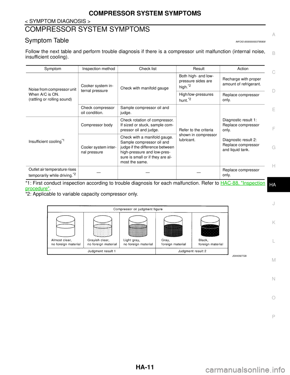
oil condition.Sample compressor oil and
judge.
Refer to the criteria
shown in compressor
lubricant.Diagnostic result 1:
Replace compressor
only.
Diagnostic result 2:
Replace compressor
and liquid tank. Insufficient cooling
*1
Compressor bodyCheck rotation of compressor.
If sized or stuck, sample com-
pressor oil and judge.
Cooler system inter-
nal pressureCheck with a manifold gauge.
Sample compressor oil and
judge if the difference between
high-pressure and low-pres-
sure is small or if they are al-
most the same.
Outlet air temperature rises
temporarily while driving.
*2—— —Replace compressor
only.
JSIIA0927GB
Page 2584 of 5121
PRECAUTIONS
HA-15
< PRECAUTION >
C
D
E
F
G
H
J
K
L
MA
B
HA
N
O
P O-Ring Part Numbers and Specifications
WARNING:
Check that all refrigerant is discharged into the recycling equipment and the pressure in the system is
less than atmospheric pressure. Then gradually loosen the discharge side hose fitting and remove it.
CAUTION:
Observe the following when replacing or cleaning refrigerant cycle components.
Store it in the same way at it is when mounted on the car when the compressor is removed. Failure
to do so causes lubricant to enter the low-pressure chamber.
Use always a torque wrench and a back-up wrench when connecting tubes.
Plug immediately all openings to prevent entry of dust and moisture after disconnecting tubes.
Connect the pipes at the final stage of the operation when installing an air conditioner in the vehicle.
Never remove the seal caps of pipes and other components until just before required for connection.
Allow components stored in cool areas to warm to working area temperature before removing seal
caps. This prevents condensation from forming inside A/C components.
Remove thoroughly moisture from the refrigeration system before charging the refrigerant.
Replace always used O-rings.
Apply lubricant to circle of the O-rings shown in illustration when connecting tube. Be careful not to
apply lubricant to threaded portion.
O-ring must be closely attached to the groove portion of tube.
Be careful not to damage O-ring and tube when replacing the O-ring.
Connect tube until a click can be heard. Then tighten the nut or bolt by hand. Check that the O-ring is
installed to tube correctly.
Connection type Piping connection point Part number QTY O-ring size
NewLow-pressure flexible hose to low-pressure pipe 92474 N8210 1 19
High-pressure pipe to condenser pipe assembly (Outlet) 92471 N8210 1 8
Condenser pipe assembly (Inlet) to high-pressure flexible
hose92472 N8210 1 12
Condenser assembly to condenser pipe as-
semblyInlet 92472 N8210 1 12
Outlet 92471 N8210 1 8
Low-pressure pipe to expansion valve 92473 N8210 1 16
High-pressure pipe to expansion valve 92471 N8210 1 8
Compressor to low-pressure flexible hose 92474 N8210 1 19
Compressor to high-pressure flexible hose 92472 N8210 1 12
Liquid tank to condenser assemblyInlet
92471 N82101
8
Outlet 1
FormerRefrigerant pressure sensor to liquid tank J2476 89956 1 10
Expansion valve to evaporator pipe assemblyInlet 92475 71L00 1 12
Outlet 92475 72L00 1 16
Evaporator to evaporator pipe assemblyInlet 92475 71L00 1 12
Outlet 92475 72L00 1 16
Name : NISSAN A/C System Oil Type S
Page 2594 of 5121
REFRIGERANT
HA-25
< ON-VEHICLE MAINTENANCE >
C
D
E
F
G
H
J
K
L
MA
B
HA
N
O
P
WARNING:
Never breath A/C refrigerant and lubricant vapor or mist. Exposure may irritate eyes, nose and throat.
Use only approved recovery/recycling recharging equipment to discharge HFC-134a (R-134a) refriger-
ant. Ventilate work area before resuming service if accidental system discharge occurs. Additional
health and safety information may be obtained from refrigerant and lubricant manufacturers.
1.CHECK A/C SYSTEM
1. Check that A/C system operates normally. Refer to the following.
-HAC-8, "
Description & Inspection" (WITHOUT 7 INCH DISPLAY)
-HAC-108, "
WITHOUT INTELLIGENT AIR CONDITIONER SYSTEM : Description & Inspection" [WITH 7
INCH DISPLAY (WITHOUT INTELLIGENT AIR CONDITIONER SYSTEM)]
-HAC-112, "
WITH INTELLIGENT AIR CONDITIONER SYSTEM : Description & Inspection" [WITH 7 INCH
DISPLAY (WITH INTELLIGENT AIR CONDITIONER SYSTEM)]
2. Check if there is a large amount of leakage of refrigerant or oil.
CAUTION:
Never perform the lubricant return operation if a large amount of leakage of lubricant is detected.
Is the inspection result normal?
YES >> GO TO 2.
NO >> Check for refrigerant leakage. Refer to HA-32, "
Inspection".
2.LUBRICANT RETURN OPERATION
1. Start the engine and run it as follows.
- Engine speed: Idle - 1,200 rpm
- A/C switch: ON
- Blower speed: Max. position
- Air inlet: Recirculation (REC)
- Set temperature: FULL HOT
2. Perform lubricant return operation for approximately 10 minutes.
3. Stop the engine.
>> GO TO 3.
3.CHECK RECOVERY/RECYCLING RECHARGING EQUIPMENT
1. Operate recovery/recycling recharging equipment.
CAUTION:
Follow the instructions of the manufacturer for the handling or maintenance of the equipment.
Never fill the equipment with undesignated refrigerant.
2. Check the gauge pressure of recovery/recycling recharging equipment.
Is there pressure?
YES >> GO TO 4.
NO >> GO TO 5.
4.DISCHARGE REFRIGERANT INSIDE PIPES
Discharge the refrigerant from the high-pressure hose and low-pressure hose of recovery/recycling recharging
equipment.
>> GO TO 5.
5.CONNECT RECOVERY/RECYCLING RECHARGING EQUIPMENT
1. Remove the service valve caps from the vehicle.
2. Connect recovery/recycling recharging equipment to the service valves.
>> GO TO 6.
6.DISCHARGE REFRIGERANT FROM THE VEHICLE
Operate recovery/recycling recharging equipment to discharge the refrigerant from the vehicle.
Page 2597 of 5121
HA-28
< ON-VEHICLE MAINTENANCE >
LUBRICANT
LUBRICANT
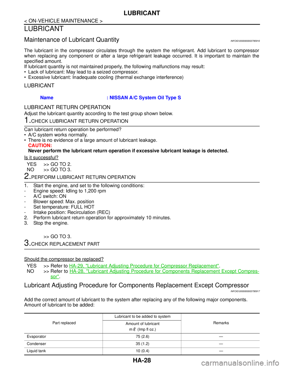
Maintenance of Lubricant QuantityINFOID:0000000003795916
The lubricant in the compressor circulates through the system the refrigerant. Add lubricant to compressor
when replacing any component or after a large refrigerant leakage occurred. It is important to maintain the
specified amount.
If lubricant quantity is not maintained properly, the following malfunctions may result:
Lack of lubricant: May lead to a seized compressor.
Excessive lubricant: Inadequate cooling (thermal exchange interference)
LUBRICANT
LUBRICANT RETURN OPERATION
Adjust the lubricant quantity according to the test group shown below.
1.CHECK LUBRICANT RETURN OPERATION
Can lubricant return operation be performed?
A/C system works normally.
There is no evidence of a large amount of lubricant leakage.
CAUTION:
Never perform the lubricant return operation if excessive lubricant leakage is detected.
Is it successful?
YES >> GO TO 2.
NO >> GO TO 3.
2.PERFORM LUBRICANT RETURN OPERATION
1. Start the engine, and set to the following conditions:
- Engine speed: Idling to 1,200 rpm
- A/C switch: ON
- Blower speed: Max. position
- Set temperature: FULL HOT
- Intake position: Recirculation (REC)
2. Perform lubricant return operation for approximately 10 minutes.
3. Stop the engine.
>> GO TO 3.
3.CHECK REPLACEMENT PART
Should the compressor be replaced?
YES >> Refer to HA-29, "Lubricant Adjusting Procedure for Compressor Replacement".
NO >> Refer to HA-28, "
Lubricant Adjusting Procedure for Components Replacement Except Compres-
sor".
Lubricant Adjusting Procedure for Components Replacement Except Compressor
INFOID:0000000003795917
Add the correct amount of lubricant to the system after replacing any of the following major components.
Amount of lubricant to be added:Name : NISSAN A/C System Oil Type S
Part replacedLubricant to be added to system
Remarks
Amount of lubricant
m (Imp fl oz.)
Evaporator 75 (2.6) —
Condenser 35 (1.2) —
Liquid tank 10 (0.4) —