2008 NISSAN TEANA oil temperature
[x] Cancel search: oil temperaturePage 3289 of 5121

MWI
DIAGNOSIS SYSTEM (METER)
MWI-35
< FUNCTION DIAGNOSIS >
C
D
E
F
G
H
I
J
K
L
MB A
O
P
NOTE:
Some items are not available according to vehicle specification.
SPECIAL FUNCTION
Special menu
W/L ON HISTORY
Stores histories when warning/indicator lamp is turned on.
“W/L ON HISTORY” indicates the “TIME” when the warning/ indicator lamp is turned on.
The “TIME” above is :
SHIFT IND
[P, R, N, D, L]Status of shift position indicator detected from shift position signal and manual
mode indicator signal is received from TCM via CAN communication.
O/D OFF SW
[On/Off] Status of sport mode switch.
M RANGE SW
[On/Off]This item is displayed, but cannot be monitored.
NM RANGE SW
[On/Off]This item is displayed, but cannot be monitored.
AT SFT UP SW
[On/Off]This item is displayed, but cannot be monitored.
AT SFT DWN SW
[On/Off]This item is displayed, but cannot be monitored.
ST SFT UP SW
[On/Off]This item is displayed, but cannot be monitored.
ST SFT DWN SW
[On/Off]This item is displayed, but cannot be monitored.
PKB SW
[On/Off]Status of parking brake switch.
BUCKLE SW
[On/Off]Status of seat belt buckle switch.
BRAKE OIL SW
[On/Off]Status of brake fluid level switch.
DISTANCE
[km]Value of possible driving distance calculated by combination meter.
A/C AMP CONN
[On/Off]Input status of A/C auto amp. connection recognition signal.
ENTER SW
[On/Off]Status of (ENTER) switch.
SELECT SW
[On/Off]Status of (SELECT) switch.
OUTSIDE TEMP
[°C or °F]Ambient air temperature value converted from ambient sensor signal received
from ambient sensor.
NOTE:
This may not match with the temperature value indicated on the information dis-
play. (Because the information display value is a corrected value from the ambient
sensor input value.)
FUEL LOW SIG
[On/Off]Status of fuel level low warning signal to output to AV control unit via CAN com-
munication.
BUZZER
[On/Off]XBuzzer status (in the combination meter) is detected from the buzzer output signal
received from each unit via CAN communication and the warning output condition
of the combination meter. Display item [Unit]MAIN
SIGNALSDescription
Display item Description
W/L ON HISTORY Lighting history of warning lamp and indicator lamp can be checked.
Page 3309 of 5121

MWI
COMBINATION METER
MWI-55
< ECU DIAGNOSIS >
C
D
E
F
G
H
I
J
K
L
MB A
O
P
NOTE:
Some items are not available according to vehicle specification.M RANGE SWIgnition switch
ONNOTE:
This item is displayed, but cannot be moni-
tored.On
NM RANGE SWIgnition switch
ONNOTE:
This item is displayed, but cannot be moni-
tored.Off
AT SFT UP SWIgnition switch
ONNOTE:
This item is displayed, but cannot be moni-
tored.On
AT SFT DWN SWIgnition switch
ONNOTE:
This item is displayed, but cannot be moni-
tored.On
ST SFT UP SWIgnition switch
ONNOTE:
This item is displayed, but cannot be moni-
tored.Off
ST SFT DWN SWIgnition switch
ONNOTE:
This item is displayed, but cannot be moni-
tored.Off
PKB SWIgnition switch
ONParking brake switch ON On
Parking brake switch OFF Off
BUCKLE SWIgnition switch
ONSeat belt not fastened On
Seat belt fastened Off
BRAKE OIL SWIgnition switch
ONBrake fluid level switch ON On
Brake fluid level switch OFF Off
DISTANCE
[km]Ignition switch
ON—Possible driving distance calculated by
combination meter
A/C AMP CONNIgnition switch
ONReceives A/C auto amp. connection recog-
nition signalOn
Other than the above Off
ENTER SWIgnition switch
ONWhen is pressedOn
Other than the above Off
SELECT SWIgnition switch
ONWhen is pressedOn
Other than the above Off
OUTSIDE TEMP
[°C] or [°F]Ignition switch
ON—Equivalent to ambient temperature
NOTE:
This may not match the indicated value
on the information display.
FUEL LOW SIGIgnition switch
ONLow fuel warning signal output On
Low fuel warning signal not output Off
BUZZERIgnition switch
ONBuzzer ON On
Buzzer OFF Off Monitor Item Condition Value/Status
Page 3321 of 5121

MWI
COMBINATION METER
MWI-67
< ECU DIAGNOSIS >
C
D
E
F
G
H
I
J
K
L
MB A
O
P
DTC IndexINFOID:0000000003792591
Function Specifications
Speedometer
Reset to zero by suspending communication. Tachometer
Water temperature gauge
Illumination controlWhen suspending communication, changes to nighttime
mode.
Information displayDoor open warning
The display turns off by suspending communication. Trunk open warning
Parking brake release warning
Instantaneous fuel warning When reception time of an abnormal signal is 2 seconds or
less, the last received datum is used for calculation to indi-
cate the result.
When reception time of an abnormal signal is more than two
seconds, the last result calculated during normal condition
is indicated. Average fuel consumption
Average vehicle speed
Travel distance
Buzzer The buzzer turns off by suspending communication.
Warning lamp/indicator
lampABS warning lamp
The lamp turns on by suspending communication. VDC OFF indicator lamp
SLIP indicator lamp
Brake warning lamp
High beam indicator lamp
The lamp turns off by suspending communication. Front fog light indicator lamp
Rear fog light indicator lamp
Turn signal indicator lamp
Light indicator lamp
Oil pressure warning lamp
Malfunction indicator lamp
CRUISE indicator lamp
SPORT indicator lamp
Key warning lamp
Display contents of CONSULT-III Diagnostic item is detected when ... Refer to
CAN COMM CIRCUIT
[U1000]When combination meter is not transmitting or receiving CAN communication signal
for 2 seconds or more.MWI-37,
"Diagnosis
Procedure"
CONTROL UNIT (CAN)
[U1010]When detecting error during the initial diagnosis of the CAN controller of combina-
tion meter.MWI-38, "Diagnosis
Procedure"
VEHICLE SPEED
[B2205]The abnormal vehicle speed signal is input from the ABS actuator and electric unit
(control unit) for 2 seconds or more.MWI-39, "Diagnosis
Procedure"
ENGINE SPEED
[B2267]If ECM continuously transmits abnormal engine speed signals for 2 seconds or
more.MWI-40, "Diagnosis
Procedure"
WATER TEMP
[B2268]If ECM continuously transmits abnormal engine coolant temperature signals for 60
seconds or more.MWI-41, "Diagnosis
Procedure"
Page 4221 of 5121
DRIVER AIR BAG MODULE
SR-7
< ON-VEHICLE REPAIR >
C
D
E
F
G
I
J
K
L
MA
B
SR
N
O
P
3. Pull out driver air bag module.
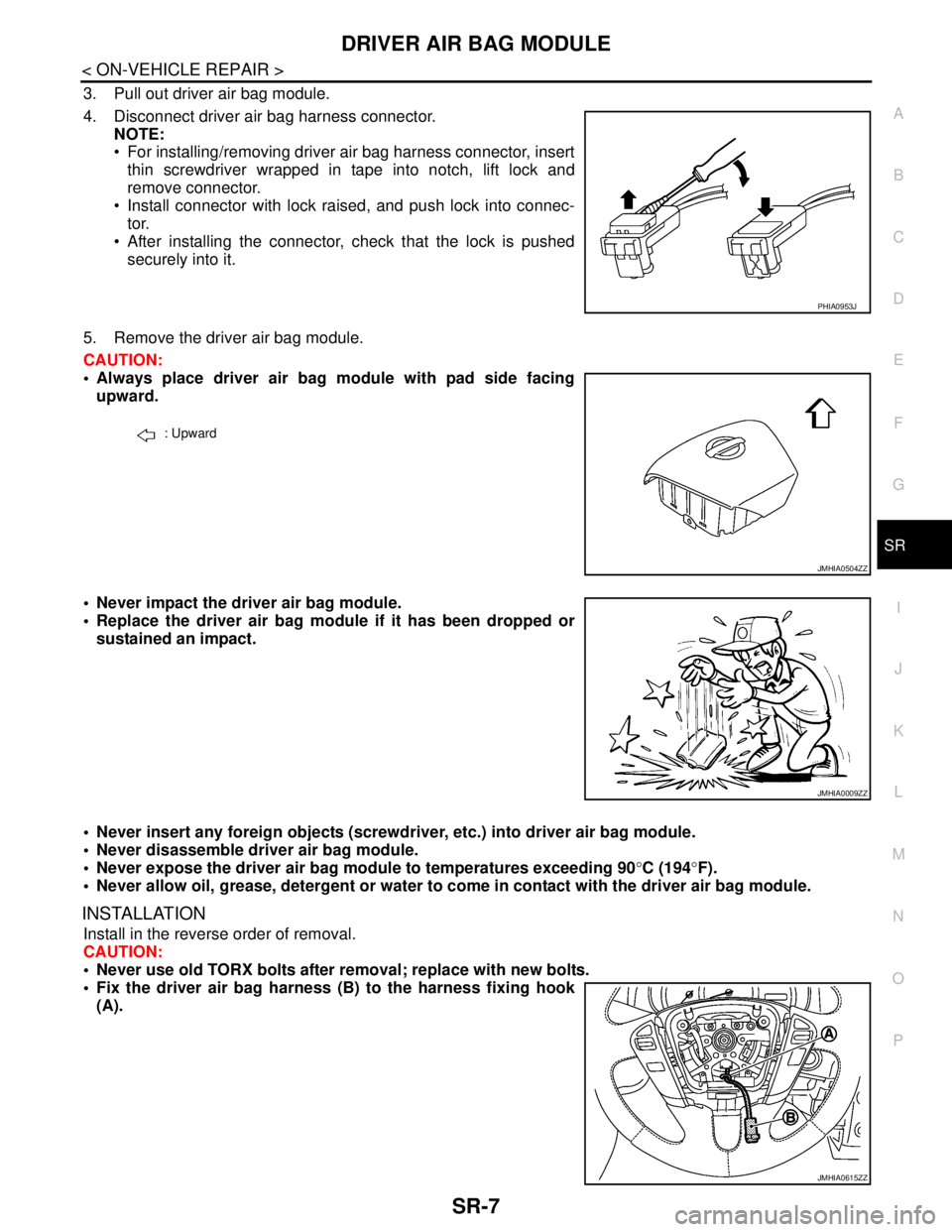
4. Disconnect driver air bag harness connector.
NOTE:
For installing/removing driver air bag harness connector, insert
thin screwdriver wrapped in tape into notch, lift lock and
remove connector.
Install connector with lock raised, and push lock into connec-
tor.
After installing the connector, check that the lock is pushed
securely into it.
5. Remove the driver air bag module.
CAUTION:
Always place driver air bag module with pad side facing
upward.
Never impact the driver air bag module.
Replace the driver air bag module if it has been dropped or
sustained an impact.
Never insert any foreign objects (screwdriver, etc.) into driver air bag module.
Never disassemble driver air bag module.
Never expose the driver air bag module to temperatures exceeding 90°C (194°F).
Never allow oil, grease, detergent or water to come in contact with the driver air bag module.
INSTALLATION
Install in the reverse order of removal.
CAUTION:
Never use old TORX bolts after removal; replace with new bolts.
Fix the driver air bag harness (B) to the harness fixing hook
(A).
PHIA0953J
: Upward
JMHIA0504ZZ
JMHIA0009ZZ
JMHIA0615ZZ
Page 4227 of 5121
FRONT PASSENGER AIR BAG MODULE
SR-13
< ON-VEHICLE REPAIR >
C
D
E
F
G
I
J
K
L
MA
B
SR
N
O
P
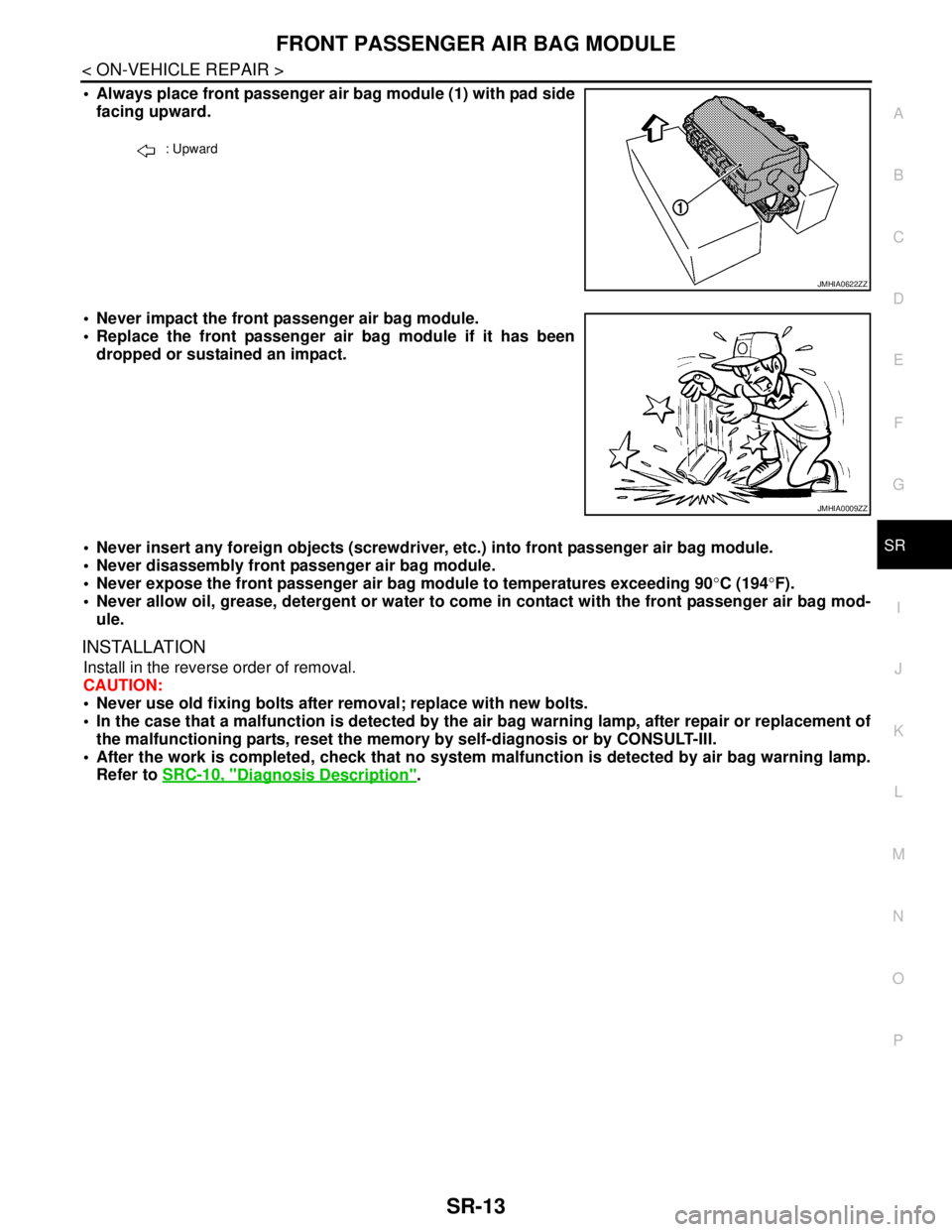
Always place front passenger air bag module (1) with pad side
facing upward.
Never impact the front passenger air bag module.
Replace the front passenger air bag module if it has been
dropped or sustained an impact.
Never insert any foreign objects (screwdriver, etc.) into front passenger air bag module.
Never disassembly front passenger air bag module.
Never expose the front passenger air bag module to temperatures exceeding 90°C (194°F).
Never allow oil, grease, detergent or water to come in contact with the front passenger air bag mod-
ule.
INSTALLATION
Install in the reverse order of removal.
CAUTION:
Never use old fixing bolts after removal; replace with new bolts.
In the case that a malfunction is detected by the air bag warning lamp, after repair or replacement of
the malfunctioning parts, reset the memory by self-diagnosis or by CONSULT-III.
After the work is completed, check that no system malfunction is detected by air bag warning lamp.
Refer to SRC-10, "
Diagnosis Description".
: Upward
JMHIA0622ZZ
JMHIA0009ZZ
Page 4229 of 5121
SIDE CURTAIN AIR BAG MODULE
SR-15
< ON-VEHICLE REPAIR >
C
D
E
F
G
I
J
K
L
MA
B
SR
N
O
P
3. Remove fixing bolts, and then remove side curtain air bag module.
CAUTION:
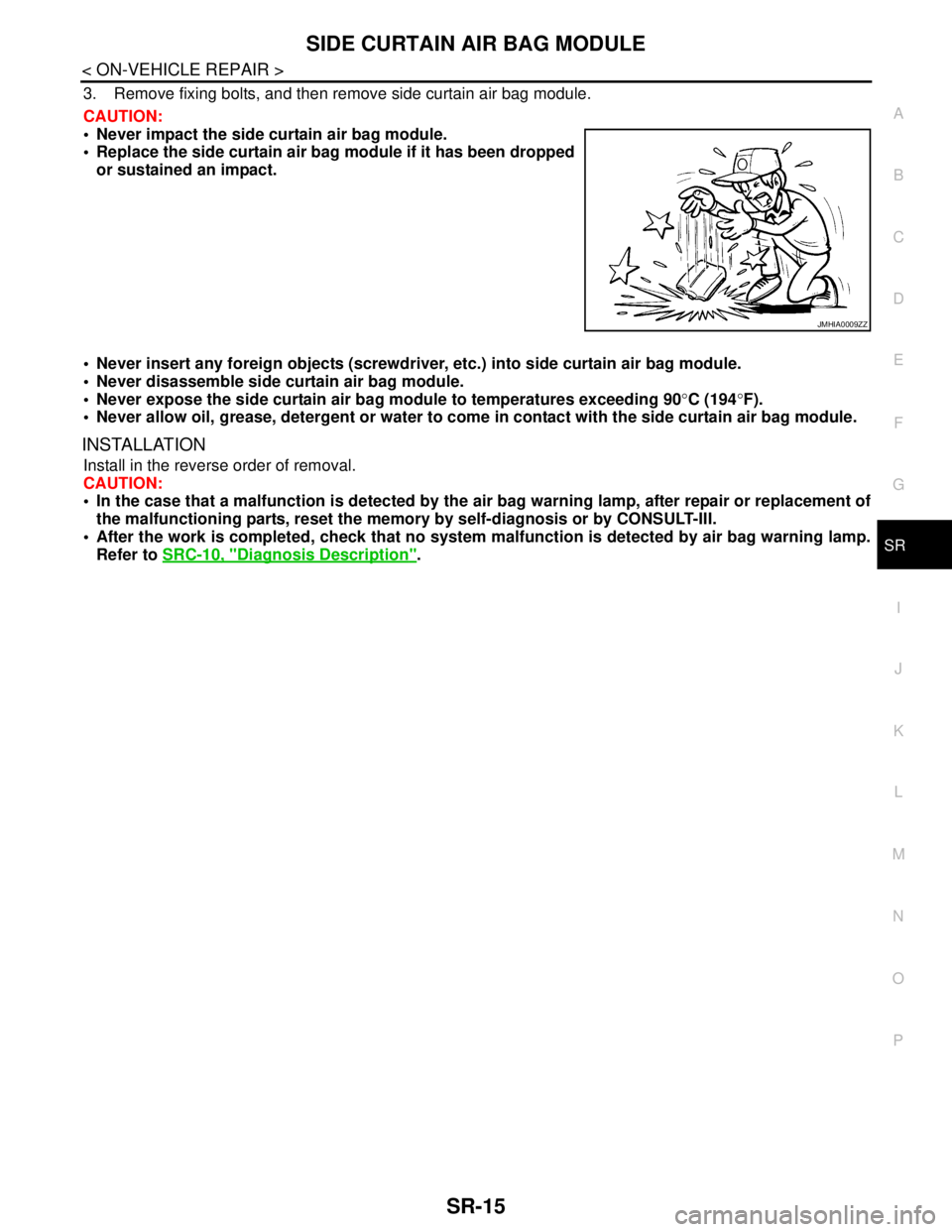
Never impact the side curtain air bag module.
Replace the side curtain air bag module if it has been dropped
or sustained an impact.
Never insert any foreign objects (screwdriver, etc.) into side curtain air bag module.
Never disassemble side curtain air bag module.
Never expose the side curtain air bag module to temperatures exceeding 90°C (194°F).
Never allow oil, grease, detergent or water to come in contact with the side curtain air bag module.
INSTALLATION
Install in the reverse order of removal.
CAUTION:
In the case that a malfunction is detected by the air bag warning lamp, after repair or replacement of
the malfunctioning parts, reset the memory by self-diagnosis or by CONSULT-III.
After the work is completed, check that no system malfunction is detected by air bag warning lamp.
Refer to SRC-10, "
Diagnosis Description".
JMHIA0009ZZ
Page 4231 of 5121
FRONT SIDE AIR BAG MODULE
SR-17
< ON-VEHICLE REPAIR >
C
D
E
F
G
I
J
K
L
MA
B
SR
N
O
P
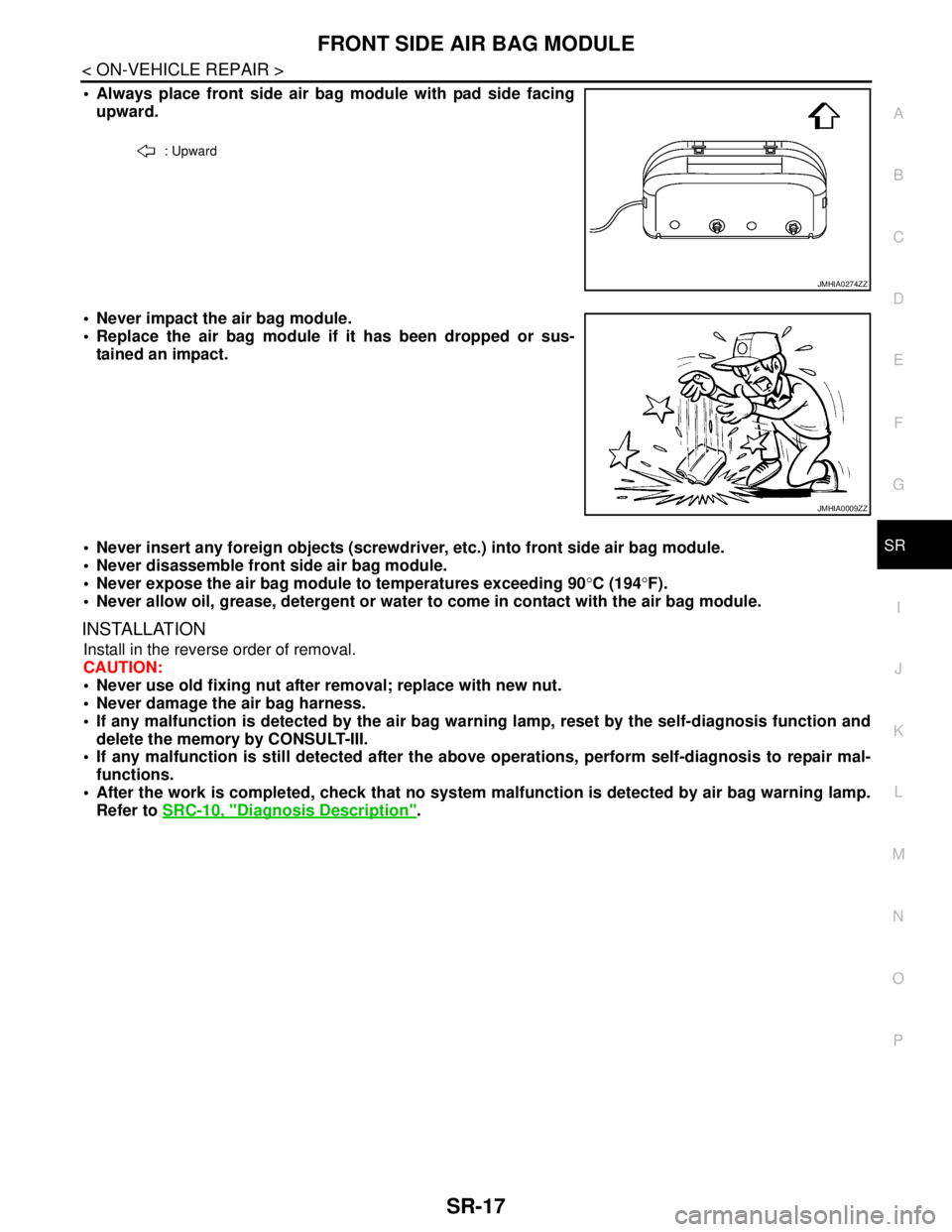
Always place front side air bag module with pad side facing
upward.
Never impact the air bag module.
Replace the air bag module if it has been dropped or sus-
tained an impact.
Never insert any foreign objects (screwdriver, etc.) into front side air bag module.
Never disassemble front side air bag module.
Never expose the air bag module to temperatures exceeding 90°C (194°F).
Never allow oil, grease, detergent or water to come in contact with the air bag module.
INSTALLATION
Install in the reverse order of removal.
CAUTION:
Never use old fixing nut after removal; replace with new nut.
Never damage the air bag harness.
If any malfunction is detected by the air bag warning lamp, reset by the self-diagnosis function and
delete the memory by CONSULT-III.
If any malfunction is still detected after the above operations, perform self-diagnosis to repair mal-
functions.
After the work is completed, check that no system malfunction is detected by air bag warning lamp.
Refer to SRC-10, "
Diagnosis Description".
: Upward
JMHIA0274ZZ
JMHIA0009ZZ
Page 4397 of 5121
POWER STEERING FLUID
ST-7
< ON-VEHICLE MAINTENANCE >
C
D
E
F
H
I
J
K
L
MA
B
ST
N
O
P
ON-VEHICLE MAINTENANCE
POWER STEERING FLUID
InspectionINFOID:0000000003826225
FLUID LEVEL
1. Check fluid level with engine stopped.
2. Ensure that fluid level is between MIN and MAX.
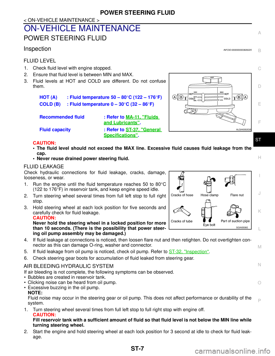
3. Fluid levels at HOT and COLD are different. Do not confuse
them.
CAUTION:
The fluid level should not exceed the MAX line. Excessive fluid causes fluid leakage from the
cap.
Never reuse drained power steering fluid.
FLUID LEAKAGE
Check hydraulic connections for fluid leakage, cracks, damage,
looseness, or wear.
1. Run the engine until the fluid temperature reaches 50 to 80°C
(122 to 176°F) in reservoir tank, and keep engine speed idle.
2. Turn steering wheel several times from full left stop to full right
stop.
3. Hold steering wheel at each lock position for five seconds and
carefully check for fluid leakage.
CAUTION:
Never hold the steering wheel in a locked position for more
than 10 seconds. (There is the possibility that power steer-
ing oil pump assembly may be damaged.)
4. If fluid leakage at connections is noticed, then loosen flare nut and then retighten. Do not overtighten con-
nector as this can damage O-ring, washer and connector.
5. If fluid leakage from oil pump is noticed, check oil pump. Refer to ST-32, "
Inspection".
6. Check steering gear boots for accumulation of fluid leaked from steering gear.
AIR BLEEDING HYDRAULIC SYSTEM
If air bleeding is not complete, the following symptoms can be observed.
Bubbles are created in reservoir tank.
Clicking noise can be heard from oil pump.
Excessive buzzing in the oil pump.
NOTE:
Fluid noise may occur in the steering gear or oil pump. This does not affect performance or durability of the
system.
1. Turn steering wheel several times from full left stop to full right stop with engine off.
CAUTION:
Fill reservoir tank with a sufficient amount of fluid so that fluid level is not below the MIN line while
turning steering wheel.
2. Start the engine and hold steering wheel at each lock position for 3 second at idle to check for fluid leak-
age.HOT (A) : Fluid temperature 50 – 80°C (122 – 176°F)
COLD (B) : Fluid temperature 0 – 30°C (32 – 86°F)
Recommended fluid : Refer to MA-11, "
Fluids
and Lubricants".
Fluid capacity : Refer to ST-37, "
General
Specifications".
ALGIA0002GB
SGIA0506E