2008 NISSAN TEANA weight
[x] Cancel search: weightPage 2592 of 5121
PREPARATION
HA-23
< PREPARATION >
C
D
E
F
G
H
J
K
L
MA
B
HA
N
O
PSealant or/and LubricantINFOID:0000000003795894
HFC-134a (R-134a) Service Tool and Equipment Never mix HFC-134a (R-134a) refrigerant and/or its specified lubricant with CFC-12 (R-12) refrigerant and/
or its lubricant.
Separate and non-interchangeable service equipment must be used for handling each type of refrigerant/
lubricant.
Refrigerant container fittings, service hose fittings and service equipment fittings (equipment which handles
refrigerant and/or lubricant) are different between CFC-12 (R-12) and HFC-134a (R-134a). This is to avoid
mixed use of the refrigerants/lubricant.
Never use adapters that convert one size fitting to another: refrigerant/lubricant contamination occurs and
compressor malfunction may result.
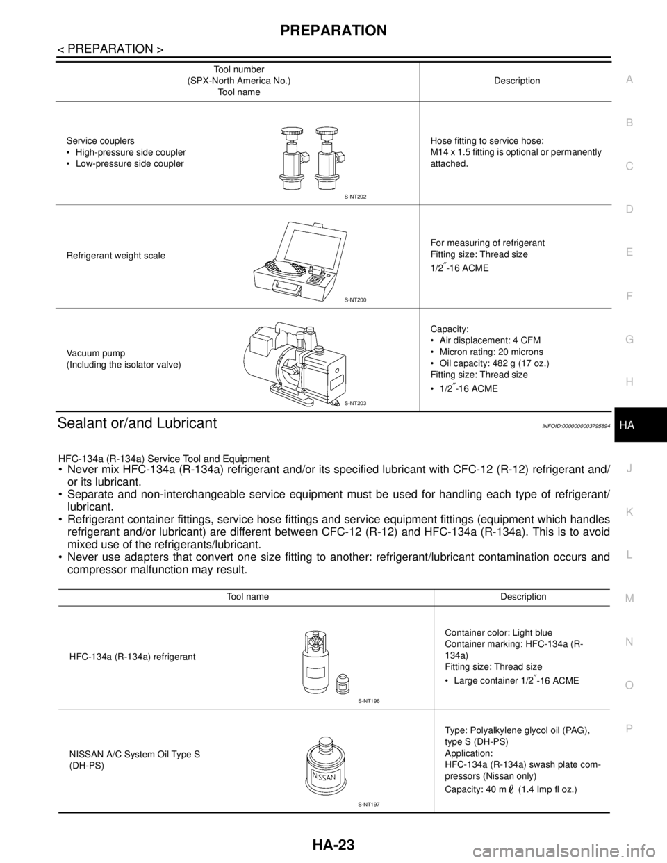
Service couplers
High-pressure side coupler
Low-pressure side couplerHose fitting to service hose:
M14 x 1.5 fitting is optional or permanently
attached.
Refrigerant weight scaleFor measuring of refrigerant
Fitting size: Thread size
1/2
″-16 ACME
Va c u u m p u m p
(Including the isolator valve)Capacity:
Air displacement: 4 CFM
Micron rating: 20 microns
Oil capacity: 482 g (17 oz.)
Fitting size: Thread size
1/2
″-16 ACME Tool number
(SPX-North America No.)
Tool nameDescription
S-NT202
S-NT200
S-NT203
Tool name Description
HFC-134a (R-134a) refrigerantContainer color: Light blue
Container marking: HFC-134a (R-
134a)
Fitting size: Thread size
Large container 1/2
″-16 ACME
NISSAN A/C System Oil Type S
(DH-PS)Type: Polyalkylene glycol oil (PAG),
type S (DH-PS)
Application:
HFC-134a (R-134a) swash plate com-
pressors (Nissan only)
Capacity: 40 m (1.4 Imp fl oz.)
S-NT196
S-NT197
Page 2593 of 5121
HA-24
< ON-VEHICLE MAINTENANCE >
REFRIGERANT
ON-VEHICLE MAINTENANCE
REFRIGERANT
Collection and ChargeINFOID:0000000003795980
SETTING OF SERVICE TOOLS AND EQUIPMENT
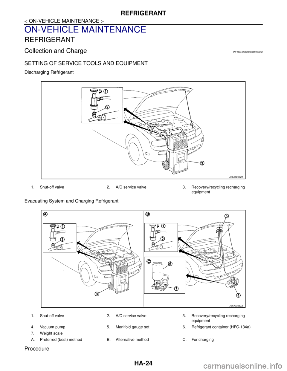
Discharging Refrigerant
Evacuating System and Charging Refrigerant
Procedure
1. Shut-off valve 2. A/C service valve 3. Recovery/recycling recharging
equipment
JSIIA0257ZZ
1. Shut-off valve 2. A/C service valve 3. Recovery/recycling recharging
equipment
4. Vacuum pump 5. Manifold gauge set 6. Refrigerant container (HFC-134a)
7. Weight scale
A. Preferred (best) method B. Alternative method C. For charging
JSIIA0258ZZ
Page 2731 of 5121
![NISSAN TEANA 2008 Service Manual PRECAUTIONS
HAC-103
< PRECAUTION >[WITHOUT 7 INCH DISPLAY]
C
D
E
F
G
H
J
K
L
MA
B
HAC
N
O
P
Never attempt to connect HFC-134a (R-134a) service couplers to a
CFC-12 (R-12) A/C system. The HFC-134a (R-1 NISSAN TEANA 2008 Service Manual PRECAUTIONS
HAC-103
< PRECAUTION >[WITHOUT 7 INCH DISPLAY]
C
D
E
F
G
H
J
K
L
MA
B
HAC
N
O
P
Never attempt to connect HFC-134a (R-134a) service couplers to a
CFC-12 (R-12) A/C system. The HFC-134a (R-1](/manual-img/5/57391/w960_57391-2730.png)
PRECAUTIONS
HAC-103
< PRECAUTION >[WITHOUT 7 INCH DISPLAY]
C
D
E
F
G
H
J
K
L
MA
B
HAC
N
O
P
Never attempt to connect HFC-134a (R-134a) service couplers to a
CFC-12 (R-12) A/C system. The HFC-134a (R-134a) couplers do
not properly connect to the CFC-12 (R-12) system. However, if an
improper connection is attempted, discharge and contamination may
occur.
REFRIGERANT WEIGHT SCALE
Verify that no refrigerant other than HFC-134a (R-134a) and speci-
fied lubricants have been used with the scale. The hose fitting must
be 1/2″-16 ACME if the scale controls refrigerant flow electronically.
CHARGING CYLINDER
Use of a charging cylinder is not recommended. Refrigerant may be vented into the air from the top valve of
the cylinder when filling the cylinder with refrigerant. Also, the accuracy of the cylinder is generally less than
that of an electronic scale or of quality recycle/recharge equipment.
Shut-off valve rotation A/C service valve
Clockwise Open
Counterclockwise Close
RHA273D
RHA274D
Page 2871 of 5121
![NISSAN TEANA 2008 Service Manual PRECAUTIONS
HAC-243
< PRECAUTION >[WITH 7 INCH DISPLAY]
C
D
E
F
G
H
J
K
L
MA
B
HAC
N
O
P
Never attempt to connect HFC-134a (R-134a) service couplers to a
CFC-12 (R-12) A/C system. The HFC-134a (R-134a NISSAN TEANA 2008 Service Manual PRECAUTIONS
HAC-243
< PRECAUTION >[WITH 7 INCH DISPLAY]
C
D
E
F
G
H
J
K
L
MA
B
HAC
N
O
P
Never attempt to connect HFC-134a (R-134a) service couplers to a
CFC-12 (R-12) A/C system. The HFC-134a (R-134a](/manual-img/5/57391/w960_57391-2870.png)
PRECAUTIONS
HAC-243
< PRECAUTION >[WITH 7 INCH DISPLAY]
C
D
E
F
G
H
J
K
L
MA
B
HAC
N
O
P
Never attempt to connect HFC-134a (R-134a) service couplers to a
CFC-12 (R-12) A/C system. The HFC-134a (R-134a) couplers do
not properly connect to the CFC-12 (R-12) system. However, if an
improper connection is attempted, discharge and contamination may
occur.
REFRIGERANT WEIGHT SCALE
Verify that no refrigerant other than HFC-134a (R-134a) and speci-
fied lubricants have been used with the scale. The hose fitting must
be 1/2″-16 ACME if the scale controls refrigerant flow electronically.
CHARGING CYLINDER
Use of a charging cylinder is not recommended. Refrigerant may be vented into the air from the top valve of
the cylinder when filling the cylinder with refrigerant. Also, the accuracy of the cylinder is generally less than
that of an electronic scale or of quality recycle/recharge equipment.
Shut-off valve rotation A/C service valve
Clockwise Open
Counterclockwise Close
RHA273D
RHA274D
Page 3187 of 5121
OIL PUMP
LU-15
< DISASSEMBLY AND ASSEMBLY >
C
D
E
F
G
H
I
J
K
L
MA
LU
N
P O
If measured/calculated values are out of the standard, replace oil pump assembly.
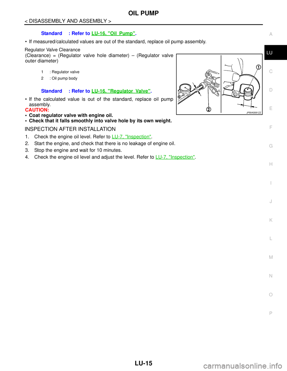
Regulator Valve Clearance
(Clearance) = (Regulator valve hole diameter) – (Regulator valve
outer diameter)
If the calculated value is out of the standard, replace oil pump
assembly.
CAUTION:
Coat regulator valve with engine oil.
Check that it falls smoothly into valve hole by its own weight.
INSPECTION AFTER INSTALLATION
1. Check the engine oil level. Refer to LU-7, "Inspection".
2. Start the engine, and check that there is no leakage of engine oil.
3. Stop the engine and wait for 10 minutes.
4. Check the engine oil level and adjust the level. Refer to LU-7, "
Inspection". Standard : Refer to LU-16, "
OilPump".
1 : Regulator valve
2 : Oil pump body
Standard : Refer to LU-16, "RegulatorVa lv e".
JPBIA0081ZZ
Page 3190 of 5121

MA-2
HEADLAMP AIMING ADJUSTMENT (HALOGEN
TYPE) : Aiming Adjustment Procedure (High
Beam) .....................................................................
30
EXHAUST SYSTEM ..................................................31
EXHAUST SYSTEM : Inspection ...........................32
CVT FLUID: RE0F10A ..............................................32
CVT FLUID: RE0F10A : Inspection ........................32
CVT FLUID: RE0F10A : Changing .........................33
CVT FLUID: RE0F09B ..............................................34
CVT FLUID: RE0F09B : Inspection ........................34
CVT FLUID: RE0F09B : Changing .........................35
WHEELS (BONDING WEIGHT TYPE) .....................35
WHEELS (BONDING WEIGHT TYPE) : Adjust-
ment ........................................................................
35
BRAKE FLUID LEVEL AND LEAKS ........................37
BRAKE FLUID LEVEL AND LEAKS : Inspection ...37
BRAKE LINES AND CABLES ..................................37
BRAKE LINES AND CABLES : Inspection .............38
BRAKE FLUID ..........................................................38
BRAKE FLUID : Changing ......................................38
DISC BRAKE ............................................................38
DISC BRAKE : Inspection ......................................38
DISC BRAKE : Front Disc Brake ............................39
DISC BRAKE : Rear Disc Brake .............................39
STEERING GEAR AND LINKAGE ...........................39
STEERING GEAR AND LINKAGE : Inspection ......39
POWER STEERING FLUID AND LINES ..................39
POWER STEERING FLUID AND LINES : Inspec-
tion ..........................................................................
40
AXLE AND SUSPENSION PARTS ...........................40
AXLE AND SUSPENSION PARTS : Inspection .....40
DRIVE SHAFT ...........................................................40
DRIVE SHAFT : Inspection .....................................41
BODY MAINTENANCE .....................................42
LOCKS, HINGES AND HOOD LATCH .....................42
LOCKS, HINGES AND HOOD LATCH : Lubricat-
ing ...........................................................................
42
SEAT BELT, BUCKLES, RETRACTORS, AN-
CHORS AND ADJUSTERS ......................................
42
SEAT BELT, BUCKLES, RETRACTORS, AN-
CHORS AND ADJUSTERS : Inspection .................
42
BODY CORROSION .................................................42
BODY CORROSION : Checking Body Corrosion ...42
SERVICE DATA AND SPECIFICATIONS
(SDS) ..........................................................
44
SERVICE DATA AND SPECIFICATIONS
(SDS) .................................................................
44
DRIVE BELTS ...........................................................44
DRIVE BELTS : Drive Belt ......................................44
ENGINE COOLANT ..................................................44
ENGINE COOLANT : Periodical Maintenance
Specification ............................................................
44
ENGINE OIL ..............................................................44
ENGINE OIL :
Periodical Maintenance Specification ....................
44
SPARK PLUG ...........................................................44
SPARK PLUG : Spark Plug ....................................44
ROAD WHEEL ..........................................................44
ROAD WHEEL : Road Wheel .................................44
Page 3223 of 5121
CHASSIS MAINTENANCE
MA-35
< ON-VEHICLE MAINTENANCE >
C
D
E
F
G
H
I
J
K
L
MB
MAN
OA
CVT FLUID CONDITION
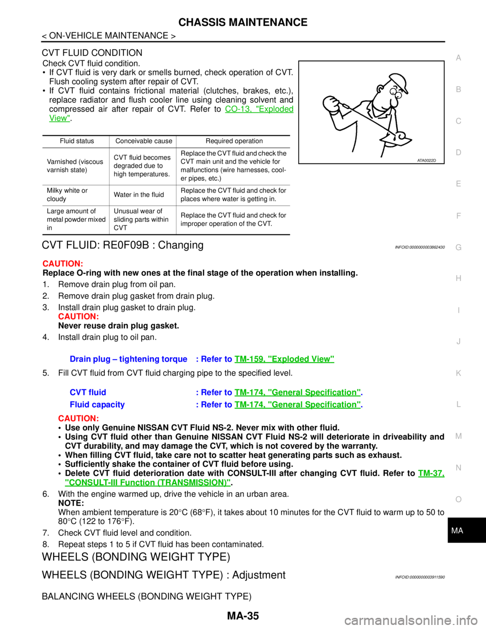
Check CVT fluid condition.
If CVT fluid is very dark or smells burned, check operation of CVT.
Flush cooling system after repair of CVT.
If CVT fluid contains frictional material (clutches, brakes, etc.),
replace radiator and flush cooler line using cleaning solvent and
compressed air after repair of CVT. Refer to CO-13, "
Exploded
View".
CVT FLUID: RE0F09B : ChangingINFOID:0000000003862430
CAUTION:
Replace O-ring with new ones at the final stage of the operation when installing.
1. Remove drain plug from oil pan.
2. Remove drain plug gasket from drain plug.
3. Install drain plug gasket to drain plug.
CAUTION:
Never reuse drain plug gasket.
4. Install drain plug to oil pan.
5. Fill CVT fluid from CVT fluid charging pipe to the specified level.
CAUTION:
Use only Genuine NISSAN CVT Fluid NS-2. Never mix with other fluid.
Using CVT fluid other than Genuine NISSAN CVT Fluid NS-2 will deteriorate in driveability and
CVT durability, and may damage the CVT, which is not covered by the warranty.
When filling CVT fluid, take care not to scatter heat generating parts such as exhaust.
Sufficiently shake the container of CVT fluid before using.
Delete CVT fluid deterioration date with CONSULT-III after changing CVT fluid. Refer to TM-37,
"CONSULT-III Function (TRANSMISSION)".
6. With the engine warmed up, drive the vehicle in an urban area.
NOTE:
When ambient temperature is 20°C (68°F), it takes about 10 minutes for the CVT fluid to warm up to 50 to
80°C (122 to 176°F).
7. Check CVT fluid level and condition.
8. Repeat steps 1 to 5 if CVT fluid has been contaminated.
WHEELS (BONDING WEIGHT TYPE)
WHEELS (BONDING WEIGHT TYPE) : AdjustmentINFOID:0000000003911590
BALANCING WHEELS (BONDING WEIGHT TYPE)
Fluid status Conceivable cause Required operation
Varnished (viscous
varnish state)CVT fluid becomes
degraded due to
high temperatures.Replace the CVT fluid and check the
CVT main unit and the vehicle for
malfunctions (wire harnesses, cool-
er pipes, etc.)
Milky white or
cloudyWater in the fluidReplace the CVT fluid and check for
places where water is getting in.
Large amount of
metal powder mixed
inUnusual wear of
sliding parts within
CVTReplace the CVT fluid and check for
improper operation of the CVT.
ATA0022D
Drain plug – tightening torque : Refer to TM-159, "Exploded View"
CVT fluid : Refer to TM-174, "General Specification".
Fluid capacity : Refer to TM-174, "
General Specification".
Page 3224 of 5121
MA-36
< ON-VEHICLE MAINTENANCE >
CHASSIS MAINTENANCE
Preparation Before Adjustment
Using releasing agent, remove double-faced adhesive tape from the road wheel.
CAUTION:
Be careful not to scratch the road wheel during removal.
After removing double-faced adhesive tape, wipe clean traces of releasing agent from the road
wheel.
Wheel Balance Adjustment
If a tire balance machine has adhesion balance weight mode settings and drive-in weight mode setting, select
and adjust a drive-in weight mode suitable for road wheels.
1. Set road wheel on tire balance machine using the center hole as a guide. Start the tire balance machine.
2. When inner and outer unbalance values are shown on the tire balance machine indicator, multiply outer
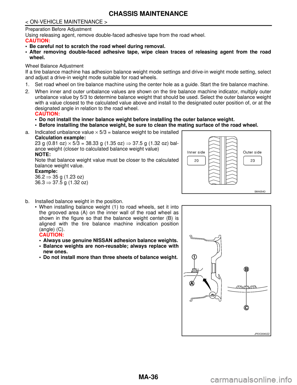
unbalance value by 5/3 to determine balance weight that should be used. Select the outer balance weight
with a value closest to the calculated value above and install to the designated outer position of, or at the
designated angle in relation to the road wheel.
CAUTION:
Do not install the inner balance weight before installing the outer balance weight.
Before installing the balance weight, be sure to clean the mating surface of the road wheel.
a. Indicated unbalance value × 5/3 = balance weight to be installed
Calculation example:
23 g (0.81 oz) × 5/3 = 38.33 g (1.35 oz) ⇒ 37.5 g (1.32 oz) bal-
ance weight (closer to calculated balance weight value)
NOTE:
Note that balance weight value must be closer to the calculated
balance weight value.
Example:
36.2 ⇒ 35 g (1.23 oz)
36.3 ⇒ 37.5 g (1.32 oz)
b. Installed balance weight in the position.
When installing balance weight (1) to road wheels, set it into
the grooved area (A) on the inner wall of the road wheel as
shown in the figure so that the balance weight center (B) is
aligned with the tire balance machine indication position
(angle) (C).
CAUTION:
Always use genuine NISSAN adhesion balance weights.
Balance weights are non-reusable; always replace with
new ones.
Do not install more than three sheets of balance weight.
SMA054D
JPEIC0040ZZ