2008 NISSAN TEANA weight
[x] Cancel search: weightPage 1863 of 5121
![NISSAN TEANA 2008 Service Manual EC-402
< SYMPTOM DIAGNOSIS >[VQ25DE, VQ35DE]
ENGINE CONTROL SYSTEM SYMPTOMS
SYMPTOM
Reference
page
HARD/NO START/RESTART (EXCP. HA)
ENGINE STALL
HESITATION/SURGING/FLAT SPOT
SPARK KNOCK/DETONATION
LA NISSAN TEANA 2008 Service Manual EC-402
< SYMPTOM DIAGNOSIS >[VQ25DE, VQ35DE]
ENGINE CONTROL SYSTEM SYMPTOMS
SYMPTOM
Reference
page
HARD/NO START/RESTART (EXCP. HA)
ENGINE STALL
HESITATION/SURGING/FLAT SPOT
SPARK KNOCK/DETONATION
LA](/manual-img/5/57391/w960_57391-1862.png)
EC-402
< SYMPTOM DIAGNOSIS >[VQ25DE, VQ35DE]
ENGINE CONTROL SYSTEM SYMPTOMS
SYMPTOM
Reference
page
HARD/NO START/RESTART (EXCP. HA)
ENGINE STALL
HESITATION/SURGING/FLAT SPOT
SPARK KNOCK/DETONATION
LACK OF POWER/POOR ACCELERATION
HIGH IDLE/LOW IDLE
ROUGH IDLE/HUNTING
IDLING VIBRATION
SLOW/NO RETURN TO IDLE
OVERHEATS/WATER TEMPERATURE HIGH
EXCESSIVE FUEL CONSUMPTION
EXCESSIVE OIL CONSUMPTION
BATTERY DEAD (UNDER CHARGE)
Warranty symptom code AA AB AC AD AE AF AG AH AJ AK AL AM HA
Fuel Fuel tank
5
5FL-9
Fuel piping 5 5 5 5 5 5FL-4
Va p o r l o c k—
Valve deposit
5 555 55 5—
Poor fuel (Heavy weight gasoline,
Low octane)—
Air Air duct
55555 5EM-26
Air cleanerEM-26
Air leakage from air duct
(Mass air flow sensor — electric
throttle control actuator)
5555EM-26
Electric throttle control actuatorEM-29
Air leakage from intake manifold/
Collector/GasketEM-29,
EM-32
Cranking Battery
111111
11PG-109
Generator circuitCHG-20
Starter circuit 3STR-5,
STR-6
Signal plate 6EM-104
PNP signal 4TM-48,
TM-214
Engine Cylinder head
55555 55 5EM-97
Cylinder head gasket 4 3
Cylinder block
66666 66 64
EM-110
Piston
Piston ring
Connecting rod
Bearing
Crankshaft
Page 1951 of 5121
EM-76
< DISASSEMBLY AND ASSEMBLY >
ENGINE STAND SETTING
DISASSEMBLY AND ASSEMBLY
ENGINE STAND SETTING
SettingINFOID:0000000003802278
NOTE:
Explained here is how to disassemble with engine stand supporting transaxle surface. When using different
type of engine stand, note with difference in steps and etc.
1. Remove the engine assembly from the vehicle. Refer to EM-67, "
Exploded View".
2. Remove the parts that may restrict installation of engine to widely use engine stand.
NOTE:
The procedure is described assuming that you use a widely use engine stand holding the surface, to
which transmission is installed.
Remove drive plate. Fix crankshaft pulley with the pulley holder (commercial service tool), and remove
mounting bolts.
Loosen mounting bolts in diagonal order.
Check for deformation or damage drive plate.
CAUTION:
Never disassemble drive plate.
Never place drive plate with signal plate facing down.
When handling signal plate, take care not to damage or scratch it.
Handle signal plate in a manner that prevents it from becoming magnetized.
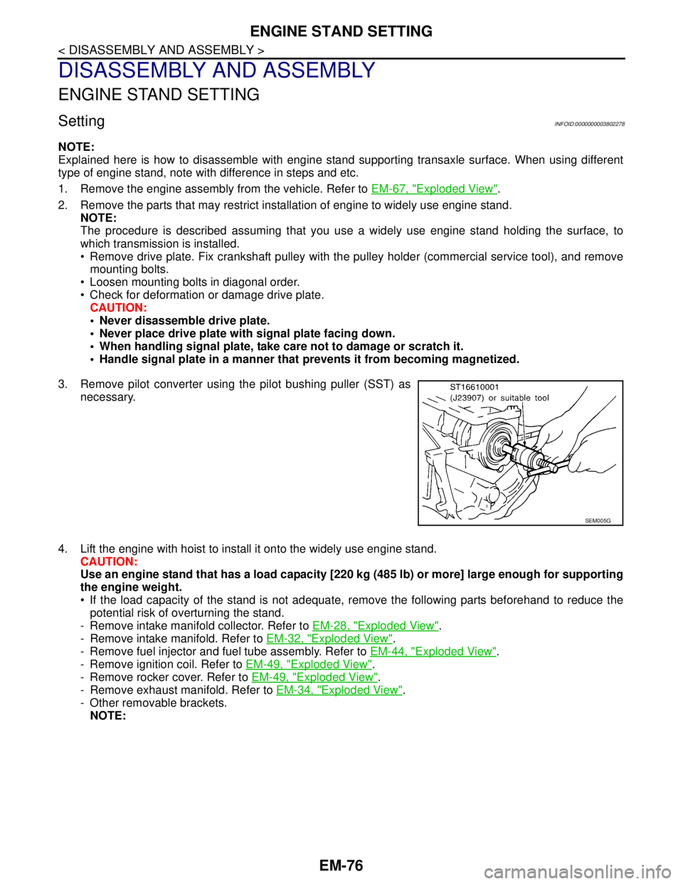
3. Remove pilot converter using the pilot bushing puller (SST) as
necessary.
4. Lift the engine with hoist to install it onto the widely use engine stand.
CAUTION:
Use an engine stand that has a load capacity [220 kg (485 lb) or more] large enough for supporting
the engine weight.
If the load capacity of the stand is not adequate, remove the following parts beforehand to reduce the
potential risk of overturning the stand.
- Remove intake manifold collector. Refer to EM-28, "
Exploded View".
- Remove intake manifold. Refer to EM-32, "
Exploded View".
- Remove fuel injector and fuel tube assembly. Refer to EM-44, "
Exploded View".
- Remove ignition coil. Refer to EM-49, "
Exploded View".
- Remove rocker cover. Refer to EM-49, "
Exploded View".
- Remove exhaust manifold. Refer to EM-34, "
Exploded View".
- Other removable brackets.
NOTE:
SEM005G
Page 1992 of 5121
CYLINDER BLOCK
EM-117
< DISASSEMBLY AND ASSEMBLY >
C
D
E
F
G
H
I
J
K
L
MA
EM
N
P O
13. Install connecting rod bearing cap.
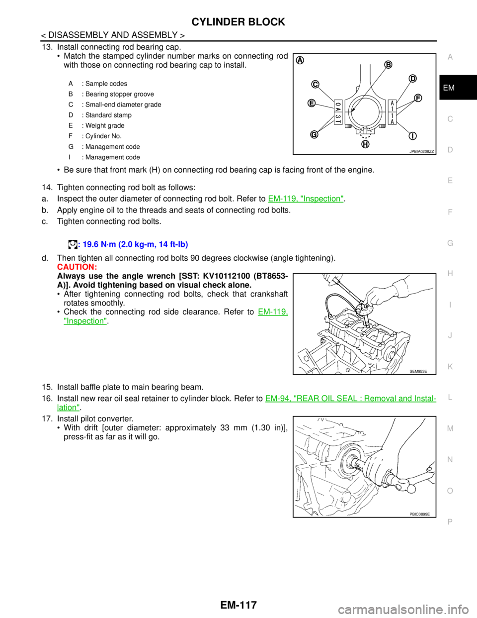
Match the stamped cylinder number marks on connecting rod
with those on connecting rod bearing cap to install.
Be sure that front mark (H) on connecting rod bearing cap is facing front of the engine.
14. Tighten connecting rod bolt as follows:
a. Inspect the outer diameter of connecting rod bolt. Refer to EM-119, "
Inspection".
b. Apply engine oil to the threads and seats of connecting rod bolts.
c. Tighten connecting rod bolts.
d. Then tighten all connecting rod bolts 90 degrees clockwise (angle tightening).
CAUTION:
Always use the angle wrench [SST: KV10112100 (BT8653-
A)]. Avoid tightening based on visual check alone.
After tightening connecting rod bolts, check that crankshaft
rotates smoothly.
Check the connecting rod side clearance. Refer to EM-119,
"Inspection".
15. Install baffle plate to main bearing beam.
16. Install new rear oil seal retainer to cylinder block. Refer to EM-94, "
REAR OIL SEAL : Removal and Instal-
lation".
17. Install pilot converter.
With drift [outer diameter: approximately 33 mm (1.30 in)],
press-fit as far as it will go.
A: Sample codes
B : Bearing stopper groove
C : Small-end diameter grade
D : Standard stamp
E : Weight grade
F : Cylinder No.
G : Management code
I : Management code
JPBIA0208ZZ
: 19.6 N·m (2.0 kg-m, 14 ft-lb)
SEM953E
PBIC0899E
Page 1997 of 5121
EM-122
< DISASSEMBLY AND ASSEMBLY >
CYLINDER BLOCK
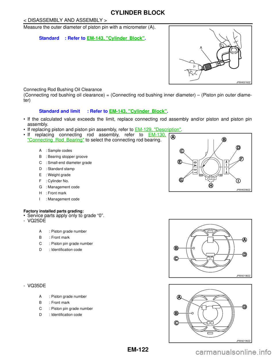
Measure the outer diameter of piston pin with a micrometer (A).
Connecting Rod Bushing Oil Clearance
(Connecting rod bushing oil clearance) = (Connecting rod bushing inner diameter) – (Piston pin outer diame-
ter)
If the calculated value exceeds the limit, replace connecting rod assembly and/or piston and piston pin
assembly.
If replacing piston and piston pin assembly, refer to EM-129, "
Description".
If replacing connecting rod assembly, refer to EM-130,
"ConnectingRodBearing" to select the connecting rod bearing.
Factory installed parts grading:
Service parts apply only to grade “0”.
- VQ25DE
- VQ35DEStandard : Refer to EM-143, "
CylinderBlock".
JPBIA0218ZZ
Standard and limit : Refer to EM-143, "CylinderBlock".
A: Sample codes
B : Bearing stopper groove
C : Small-end diameter grade
D : Standard stamp
E : Weight grade
F : Cylinder No.
G : Management code
H : Front mark
I : Management code
JPBIA0208ZZ
A : Piston grade number
B : Front mark
C : Piston pin grade number
D : Identification code
JPBIA2198ZZ
A : Piston grade number
B : Front mark
C : Piston pin grade number
D : Identification code
JPBIA2199ZZ
Page 2515 of 5121
GI-22
< FEATURES OF NEW MODEL >
IDENTIFICATION INFORMATION
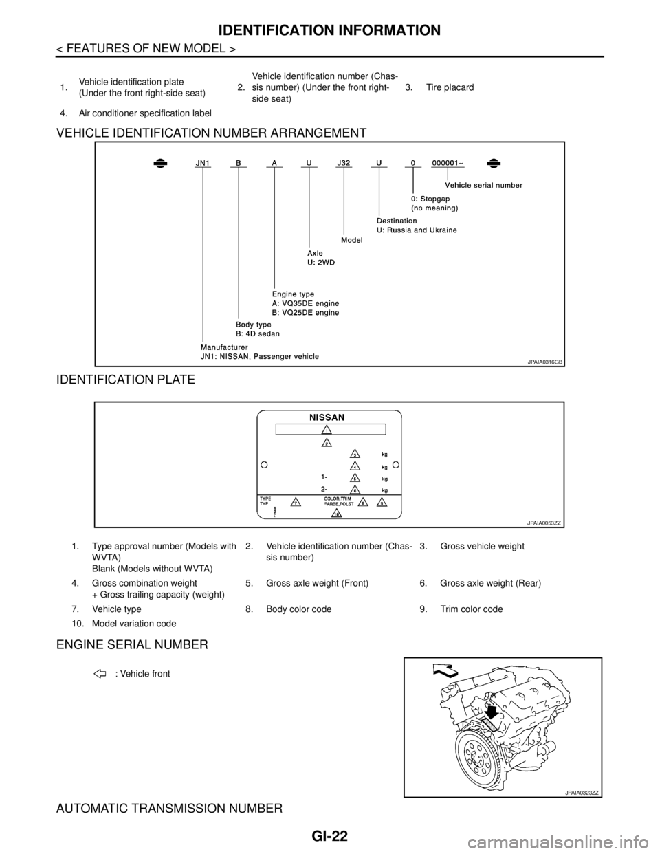
VEHICLE IDENTIFICATION NUMBER ARRANGEMENT
IDENTIFICATION PLATE
ENGINE SERIAL NUMBER
AUTOMATIC TRANSMISSION NUMBER
1.Vehicle identification plate
(Under the front right-side seat)2.Vehicle identification number (Chas-
sis number) (Under the front right-
side seat)3. Tire placard
4. Air conditioner specification label
JPAIA0316GB
1. Type approval number (Models with
WVTA)
Blank (Models without WVTA)2. Vehicle identification number (Chas-
sis number)3. Gross vehicle weight
4. Gross combination weight
+ Gross trailing capacity (weight)5. Gross axle weight (Front) 6. Gross axle weight (Rear)
7. Vehicle type 8. Body color code 9. Trim color code
10. Model variation code
JPAIA0053ZZ
: Vehicle front
JPAIA0323ZZ
Page 2518 of 5121
PRECAUTIONS
GI-25
< PRECAUTION >
C
D
E
F
G
H
I
J
K
L
MB
GI
N
O
P
If turning the steering wheel is required with the battery disconnected or discharged, follow the procedure
below before starting the repair operation.
OPERATION PROCEDURE
1. Connect both battery cables.
NOTE:
Supply power using jumper cables if battery is discharged.
2. Turn the push-button ignition switch to ACC position.
(At this time, the steering lock will be released.)
3. Disconnect both battery cables. The steering lock will remain released with both battery cables discon-
nected and the steering wheel can be turned.
4. Perform the necessary repair operation.
5. When the repair work is completed, re-connect both battery cables. With the brake pedal released, turn
the push-button ignition switch from ACC position to ON position, then to LOCK position. (The steering
wheel will lock when the push-button ignition switch is turned to LOCK position.)
6. Perform self-diagnosis check of all control units using CONSULT-III.
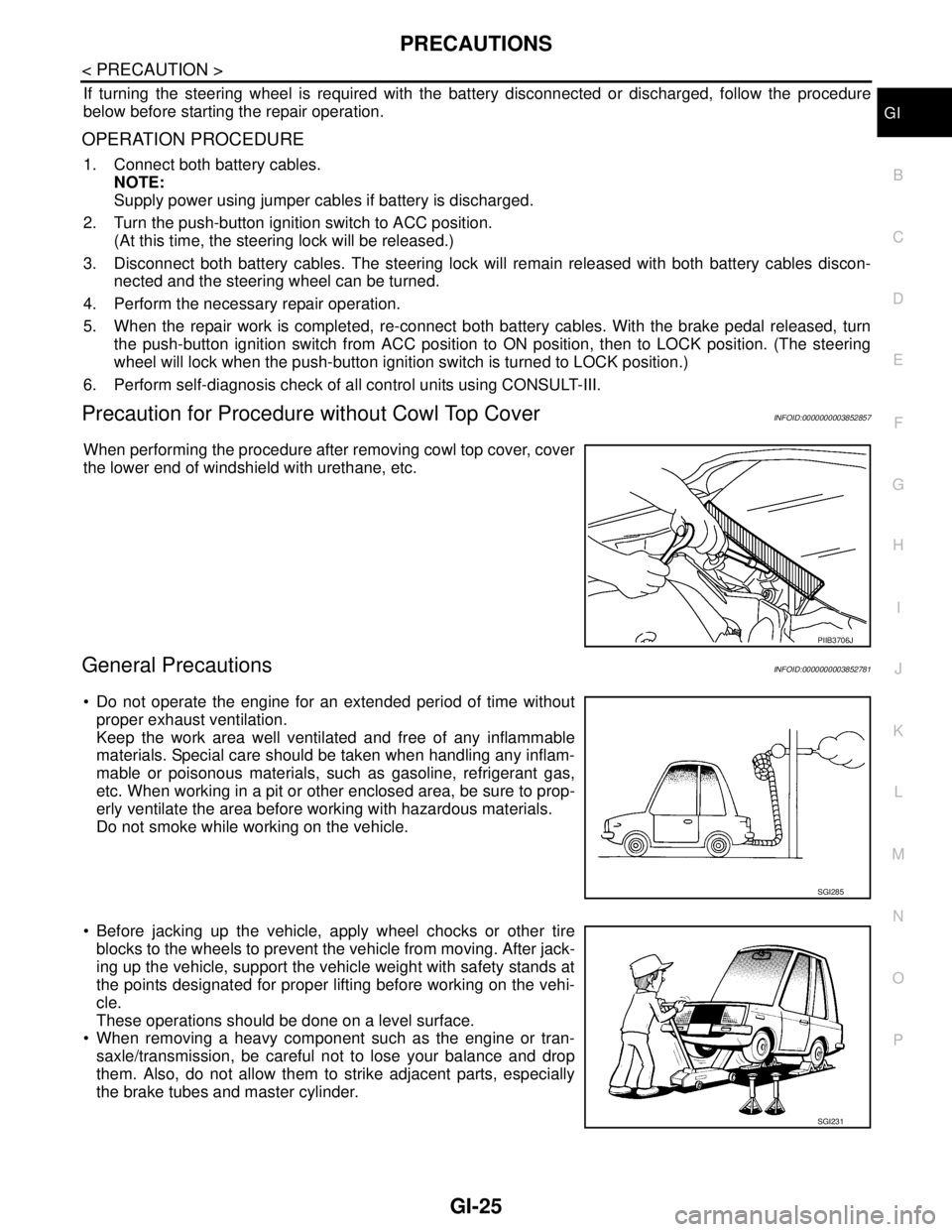
Precaution for Procedure without Cowl Top CoverINFOID:0000000003852857
When performing the procedure after removing cowl top cover, cover
the lower end of windshield with urethane, etc.
General PrecautionsINFOID:0000000003852781
Do not operate the engine for an extended period of time without
proper exhaust ventilation.
Keep the work area well ventilated and free of any inflammable
materials. Special care should be taken when handling any inflam-
mable or poisonous materials, such as gasoline, refrigerant gas,
etc. When working in a pit or other enclosed area, be sure to prop-
erly ventilate the area before working with hazardous materials.
Do not smoke while working on the vehicle.
Before jacking up the vehicle, apply wheel chocks or other tire
blocks to the wheels to prevent the vehicle from moving. After jack-
ing up the vehicle, support the vehicle weight with safety stands at
the points designated for proper lifting before working on the vehi-
cle.
These operations should be done on a level surface.
When removing a heavy component such as the engine or tran-
saxle/transmission, be careful not to lose your balance and drop
them. Also, do not allow them to strike adjacent parts, especially
the brake tubes and master cylinder.
PIIB3706J
SGI285
SGI231
Page 2586 of 5121
PRECAUTIONS
HA-17
< PRECAUTION >
C
D
E
F
G
H
J
K
L
MA
B
HA
N
O
P
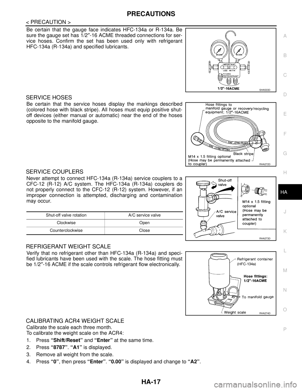
Be certain that the gauge face indicates HFC-134a or R-134a. Be
sure the gauge set has 1/2″-16 ACME threaded connections for ser-
vice hoses. Confirm the set has been used only with refrigerant
HFC-134a (R-134a) and specified lubricants.
SERVICE HOSES
Be certain that the service hoses display the markings described
(colored hose with black stripe). All hoses must equip positive shut-
off devices (either manual or automatic) near the end of the hoses
opposite to the manifold gauge.
SERVICE COUPLERS
Never attempt to connect HFC-134a (R-134a) service couplers to a
CFC-12 (R-12) A/C system. The HFC-134a (R-134a) couplers do
not properly connect to the CFC-12 (R-12) system. However, if an
improper connection is attempted, discharging and contamination
may occur.
REFRIGERANT WEIGHT SCALE
Verify that no refrigerant other than HFC-134a (R-134a) and speci-
fied lubricants have been used with the scale. The hose fitting must
be 1/2″-16 ACME if the scale controls refrigerant flow electronically.
CALIBRATING ACR4 WEIGHT SCALE
Calibrate the scale each three month.
To calibrate the weight scale on the ACR4:
1. Press “Shift/Reset” and “Enter” at the same time.
2. Press “8787”. “A1” is displayed.
3. Remove all weight from the scale.
4. Press “0”, then press “Enter”. “0.00” is displayed and change to “A2”.
SHA533D
RHA272D
Shut-off valve rotation A/C service valve
Clockwise Open
Counterclockwise Close
RHA273D
RHA274D
Page 2587 of 5121

HA-18
< PRECAUTION >
PRECAUTIONS
5. Place a known weight (dumbbell or similar weight), between 4.5 and 8.6 kg (10 and 19 lb.) on the center
of the weight scale.
6. Enter the known weight using four digits. (Example 10 lb. = 10.00, 10.5 lb. = 10.50)
7. Press “Enter”— the display returns to the vacuum mode.
8. Press “Shift/Reset” and “Enter” at the same time.
9. Press “6”— the known weight on the scale is displayed.
10. Remove the known weight from the scale. “0.00” is displayed.
11. Press “Shift/Reset” to return the ACR4 to the program mode.
CHARGING CYLINDER
Using a charging cylinder is not recommended. Refrigerant may be vented into air from cylinder’s top valve
when filling the cylinder with refrigerant. Also, the accuracy of the cylinder is generally less than that of an
electronic scale or of quality recycle/recharge equipment.