Page 1147 of 5121
CO-24
< ON-VEHICLE REPAIR >
WATER INLET AND THERMOSTAT ASSEMBLY
Inspection
INFOID:0000000003793184
INSPECTION AFTER REMOVAL
1. Check valve seating condition at ordinary room temperatures. It should seat tightly.
2. Check valve operation.
If the malfunctioning condition, when valve seating at ordinary
room temperature, or measured values are out of the standard,
replace water inlet and thermostat assembly.
INSPECTION AFTER INSTALLATION
Check for leakage of engine coolant using the radiator cap tester adapter (commercial service tool) and the
radiator cap tester (commercial service tool). Refer to CO-8, "
Inspection".
Start and warm up the engine. Visually check that there is no leakage of engine coolant. Thermostat (Standard) : Refer to CO-27, "
Thermostat".
SLC949A
Page 1148 of 5121

WATER OUTLET AND WATER PIPING
CO-25
< ON-VEHICLE REPAIR >
C
D
E
F
G
H
I
J
K
L
MA
CO
N
P O
WATER OUTLET AND WATER PIPING
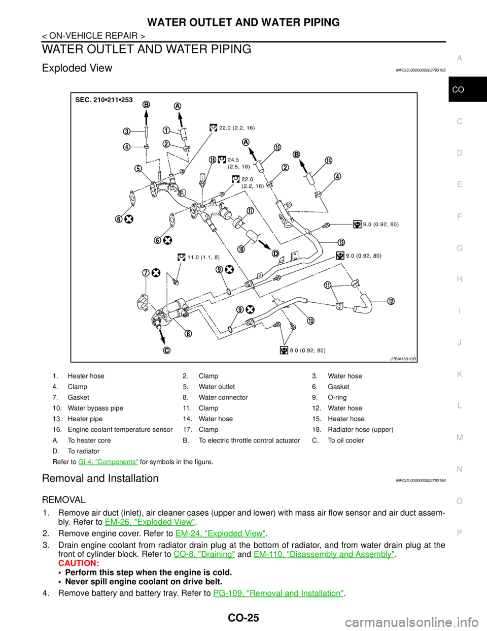
Exploded ViewINFOID:0000000003793185
Removal and InstallationINFOID:0000000003793186
REMOVAL
1. Remove air duct (inlet), air cleaner cases (upper and lower) with mass air flow sensor and air duct assem-
bly. Refer to EM-26, "
Exploded View".
2. Remove engine cover. Refer to EM-24, "
Exploded View".
3. Drain engine coolant from radiator drain plug at the bottom of radiator, and from water drain plug at the
front of cylinder block. Refer to CO-8, "
Draining" and EM-110, "Disassembly and Assembly".
CAUTION:
Perform this step when the engine is cold.
Never spill engine coolant on drive belt.
4. Remove battery and battery tray. Refer to PG-109, "
Removal and Installation".
1. Heater hose 2. Clamp 3. Water hose
4. Clamp 5. Water outlet 6. Gasket
7. Gasket 8. Water connector 9. O-ring
10. Water bypass pipe 11. Clamp 12. Water hose
13. Heater pipe 14. Water hose 15. Heater hose
16. Engine coolant temperature sensor 17. Clamp 18. Radiator hose (upper)
A. To heater core B. To electric throttle control actuator C. To oil cooler
D. To radiator
Refer to GI-4, "
Components" for symbols in the figure.
JPBIA1691GB
Page 1149 of 5121

CO-26
< ON-VEHICLE REPAIR >
WATER OUTLET AND WATER PIPING
5. Remove CVT fluid charging pipe and CVT fluid level gauge. Refer to TM-332, "Exploded View" (VQ25DE)
or TM-168, "
Exploded View" (VQ35DE).
6. Move CVT control cable aside. Refer to TM-319, "
Exploded View" (VQ25DE) or TM-157, "Exploded View"
(VQ35DE).
7. Remove vacuum pipe (front) mounting bolt from water outlet. Refer to EM-67, "
Exploded View".
8. Remove radiator hose (upper) from water outlet.
9. Remove water hoses and heater hoses.
10. Disconnect harness connectors, and move harness to aside.
11. Remove engine coolant temperature sensor as necessary.
CAUTION:
Be careful not to damage engine coolant temperature sensor.
12. Remove water outlet, heater pipe, water bypass pipe and water connector.
INSTALLATION
Note the following, and install in the reverse order of removal.
Securely insert each hose, and install clamp at a position where it does not interfere with the pipe bulge.
When inserting water bypass pipe and heater pipe into water connector, apply neutral detergent to O-ring.
InspectionINFOID:0000000003793187
INSPECTION AFTER INSTALLATION
Check for leakage of engine coolant using the radiator cap tester adapter (commercial service tool) and the
radiator cap tester (commercial service tool). Refer to CO-8, "
Inspection".
Start and warm up the engine. Visually check that there is no leakage of engine coolant.
Page 1150 of 5121
SERVICE DATA AND SPECIFICATIONS (SDS)
CO-27
< SERVICE DATA AND SPECIFICATIONS (SDS)
C
D
E
F
G
H
I
J
K
L
MA
CO
N
P O
SERVICE DATA AND SPECIFICATIONS (SDS)
SERVICE DATA AND SPECIFICATIONS (SDS)
Periodical Maintenance SpecificationINFOID:0000000003793188
ENGINE COOLANT CAPACITY (APPROXIMATE)
Unit: (lmp qt)
RadiatorINFOID:0000000003793189
Unit: kPa (bar, kg/cm2, psi)
ThermostatINFOID:0000000003793190
Standard
Engine coolant capacity (With reservoir tank at “MAX” level) 9.1 (8)
Reservoir tank0.8 (3/4)
Cap relief pressureStandard 122.3 - 151.7 (1.2 - 1.5, 1.2 - 1.5, 17.7 - 22.0)
Limit 108 (1.1, 1.1, 15.6)
Leakage test pressure 157 (1.57, 1.6, 22.8)
Valve opening temperature 80.5 - 83.5°C (177 - 182°F)
Maximum valve lift 8.6 mm/95°C (0.339 in/203°F)
Valve closing temperature 77°C (171°F)
Page 1412 of 5121
![NISSAN TEANA 2008 Service Manual DLK-196
< ON-VEHICLE REPAIR >[WITH INTELLIGENT KEY SYSTEM]
RADIATOR CORE SUPPORT
RADIATOR CORE SUPPORT
Exploded ViewINFOID:0000000003795070
Removal and InstallationINFOID:0000000003795071
REMOVAL
1. U NISSAN TEANA 2008 Service Manual DLK-196
< ON-VEHICLE REPAIR >[WITH INTELLIGENT KEY SYSTEM]
RADIATOR CORE SUPPORT
RADIATOR CORE SUPPORT
Exploded ViewINFOID:0000000003795070
Removal and InstallationINFOID:0000000003795071
REMOVAL
1. U](/manual-img/5/57391/w960_57391-1411.png)
DLK-196
< ON-VEHICLE REPAIR >[WITH INTELLIGENT KEY SYSTEM]
RADIATOR CORE SUPPORT
RADIATOR CORE SUPPORT
Exploded ViewINFOID:0000000003795070
Removal and InstallationINFOID:0000000003795071
REMOVAL
1. Use refrigerant collecting equipment to discharge the refrigerant. Refer to HA-24, "Collection and
Charge".
2. Remove front under cover. Refer to EXT-28, "
Removal and Installation".
3. Drain engine coolant from radiator. Refer to CO-8, "
Draining".
4. Remove front bumper fascia, energy absorber and bumper reinforcement. Refer to EXT-12, "
Removal
and Installation".
5. Remove mounting clips and remove air duct cover.
6. Remove hood lock opener and hood lock. Refer to DLK-220, "
Removal and Installation".
7. Disconnect connector of horn (HIGH/LOW), and then remove horn (HIGH/LOW). Refer to HRN-6,
"Removal and Installation".
8. Disconnect connector of gas sensor, and then remove gas sensor (with intelligent air conditioner system).
Refer to VTL-82, "
WITH INTELLIGENT AIR CONDITIONER SYSTEM : Removal and Installation".
9. Remove bumper retainer assembly. Refer to EXT-12, "
Removal and Installation".
10. Remove air guide (RH/LH).
11. Remove front combination lamp (RH/LH). Refer to EXL-181, "
Removal and Installation" (XENON TYPE)
or EXL-343, "
Removal and Installation" (HALOGEN TYPE).
12. Disconnect connector of ambient sensor. Refer to VTL-24, "
Removal and Installation" (WITHOUT 7 INCH
DISPLAY) or VTL-81, "
Removal and Installation" (WITH 7 INCH DISPLAY).
1. Radiator upper hose bracket 2. Hood switch bracket 3. Air duct cover
4. Air guide (RH/LH) 5. Radiator core support
: Pawl
JMKIA2382ZZ
Page 1413 of 5121
![NISSAN TEANA 2008 Service Manual RADIATOR CORE SUPPORT
DLK-197
< ON-VEHICLE REPAIR >[WITH INTELLIGENT KEY SYSTEM]
C
D
E
F
G
H
I
J
L
MA
B
DLK
N
O
P
13. Disconnect connector of refrigerant pressure sensor. Refer to HA-50, "Exploded Vie NISSAN TEANA 2008 Service Manual RADIATOR CORE SUPPORT
DLK-197
< ON-VEHICLE REPAIR >[WITH INTELLIGENT KEY SYSTEM]
C
D
E
F
G
H
I
J
L
MA
B
DLK
N
O
P
13. Disconnect connector of refrigerant pressure sensor. Refer to HA-50, "Exploded Vie](/manual-img/5/57391/w960_57391-1412.png)
RADIATOR CORE SUPPORT
DLK-197
< ON-VEHICLE REPAIR >[WITH INTELLIGENT KEY SYSTEM]
C
D
E
F
G
H
I
J
L
MA
B
DLK
N
O
P
13. Disconnect connector of refrigerant pressure sensor. Refer to HA-50, "Exploded View".
14. Remove mounting bolt, and then remove engine coolant reservoir tank. Refer to CO-13, "
Exploded View".
15. Remove mounting bolts, and then disconnect condenser pipe assembly. Refer to HA-48, "
Exploded
View".
16. Remove condenser. Refer to HA-46, "
Removal and Installation".
17. Remove mounting nut of radiator upper hose from radiator core support, and then remove radiator upper
hose and hood switch bracket. Refer to CO-25, "
Exploded View".
18. Disconnect radiator upper hose from radiator pipe (upper). Refer to CO-25, "
Exploded View".
19. Disconnect radiator lower hose (3). Refer to CO-25, "
Exploded View".
20. Disconnect CVT fluid cooler hose on radiator side. Refer to TM-165, "
Exploded View" (CVT: RE0F09B) or
TM-329, "
Exploded View" (CVT: RE0F10A).
21. Remove power steering oil cooler pipe from radiator core sup-
port at point shown by arrows in the figure.
22. Disconnect connectors of the following parts.
Cooling fan (RH/LH). Refer to CO-16, "
Exploded View".
Crash zone sensor. Refer to SR-18, "
Removal and Installation".
23. Remove radiator upper clip. Refer to CO-13, "
Exploded View".
24. Remove all harness clips from radiator core support.
CAUTION:
Never damage radiator.
25. Support hood assembly with a proper material to prevent it from falling.
WARNING:
Bodily injury may occur if no supporting rod is holding the hood open when removing the hood
stay.
26. Remove hood support rod. Refer to DLK-195, "
HOOD SUPPORT ROD : Removal and Installation".
27. Remove mounting bolts, and then remove radiator core support.
CAUTION:
Operate with two workers, because of its heavy weight.
Never damage power steering oil cooler pipe.
28. Remove the following parts after removing radiator core support.
Radiator lower hose, radiator upper hose, radiator pipe. Refer to CO-25, "
Exploded View".
Radiator. Refer to CO-13, "
Exploded View".
Cooling fan (RH/LH). Refer to CO-16, "
Exploded View".
Crash zone sensor. Refer to SR-18, "
Exploded View".
Power steering oil cooler pipe clip. Refer to ST-34, "
Exploded View".
INSTALLATION
Install in the reverse order of removal.
JMKIA2395ZZ
: harness clip
JMKIA2396ZZ
Page 1414 of 5121
DLK-198
< ON-VEHICLE REPAIR >[WITH INTELLIGENT KEY SYSTEM]
RADIATOR CORE SUPPORT
CAUTION:
After installation, inspection and replenish the following.
- Engine coolant. Refer to CO-8, "
Inspection", CO-9, "Refilling".
- CVT fluid. Refer to TM-142, "
Inspection", TM-143, "Changing" (CVT: RE0F09B) or TM-304, "Inspec-
tion", TM-305, "Changing" (CVT: RE0F10A).
After installation, adjust the following parts.
- Front combination lamp. EXL-174, "
Aiming Adjustment Procedure (Low Beam)", EXL-175, "Aiming
Adjustment Procedure (High Beam)" (XENON TYPE) or EXL-337, "Aiming Adjustment Procedure
(Low Beam)", EXL-338, "Aiming Adjustment Procedure (High Beam)" (HALOGEN TYPE).
Page 1472 of 5121
![NISSAN TEANA 2008 Service Manual INSPECTION AND ADJUSTMENT
EC-11
< BASIC INSPECTION >[VQ25DE, VQ35DE]
C
D
E
F
G
H
I
J
K
L
MA
EC
N
P O
INSPECTION AND ADJUSTMENT
BASIC INSPECTION
BASIC INSPECTION : Special Repair RequirementINFOID:0000 NISSAN TEANA 2008 Service Manual INSPECTION AND ADJUSTMENT
EC-11
< BASIC INSPECTION >[VQ25DE, VQ35DE]
C
D
E
F
G
H
I
J
K
L
MA
EC
N
P O
INSPECTION AND ADJUSTMENT
BASIC INSPECTION
BASIC INSPECTION : Special Repair RequirementINFOID:0000](/manual-img/5/57391/w960_57391-1471.png)
INSPECTION AND ADJUSTMENT
EC-11
< BASIC INSPECTION >[VQ25DE, VQ35DE]
C
D
E
F
G
H
I
J
K
L
MA
EC
N
P O
INSPECTION AND ADJUSTMENT
BASIC INSPECTION
BASIC INSPECTION : Special Repair RequirementINFOID:0000000003856444
1.INSPECTION START
1. Check service records for any recent repairs that may indicate a related malfunction, or a current need for
scheduled maintenance.
2. Open engine hood and check the following:
- Harness connectors for improper connections
- Wiring harness for improper connections, pinches and cut
- Vacuum hoses for splits, kinks and improper connections
- Hoses and ducts for leaks
- Air cleaner clogging
- Gasket
3. Confirm that electrical or mechanical loads are not applied.
- Head lamp switch is OFF.
- Air conditioner switch is OFF.
- Rear window defogger switch is OFF.
- Steering wheel is in the straight-ahead position, etc.
4. Start engine and warm it up until engine coolant temperature
indicator points the middle of gauge.
Ensure engine stays below 1,000 rpm.
5. Run engine at about 2,000 rpm for about 2 minutes under no
load.
6. Check that no DTC is displayed with CONSULT-III or GST.
Are any DTCs detected?
YES >> GO TO 2.
NO >> GO TO 3.
2.REPAIR OR REPLACE
Repair or replace components as necessary according to corresponding Diagnostic Procedure.
>> GO TO 3
3.CHECK TARGET IDLE SPEED
1. Run engine at about 2,000 rpm for about 2 minutes under no load.
SEF983U
SEF976U
SEF977U