2008 NISSAN TEANA headlamp
[x] Cancel search: headlampPage 4876 of 5121
![NISSAN TEANA 2008 Service Manual PRECAUTIONS
VTL-65
< PRECAUTION >[WITH 7 INCH DISPLAY]
C
D
E
F
G
H
J
K
L
MA
B
VTL
N
O
P
Precaution for Procedure without Cowl Top CoverINFOID:0000000003894447
When performing the procedure after remov NISSAN TEANA 2008 Service Manual PRECAUTIONS
VTL-65
< PRECAUTION >[WITH 7 INCH DISPLAY]
C
D
E
F
G
H
J
K
L
MA
B
VTL
N
O
P
Precaution for Procedure without Cowl Top CoverINFOID:0000000003894447
When performing the procedure after remov](/manual-img/5/57391/w960_57391-4875.png)
PRECAUTIONS
VTL-65
< PRECAUTION >[WITH 7 INCH DISPLAY]
C
D
E
F
G
H
J
K
L
MA
B
VTL
N
O
P
Precaution for Procedure without Cowl Top CoverINFOID:0000000003894447
When performing the procedure after removing cowl top cover, cover
the lower end of windshield with urethane, etc.
Precautions For Xenon Headlamp ServiceINFOID:0000000003894448
WARNING:
Comply with the following warnings to prevent any serious accident.
Disconnect the battery cable (negative terminal) or the power supply fuse before installing, remov-
ing, or touching the xenon headlamp (bulb included). The xenon headlamp contains high-voltage
generated parts.
Never work with wet hands.
Check the xenon headlamp ON-OFF status after assembling it to the vehicle. Never turn the xenon
headlamp ON in other conditions. Connect the power supply to the vehicle-side connector.
(Turning it ON outside the lamp case may cause fire or visual impairments.)
Never touch the bulb glass immediately after turning it OFF. It is extremely hot.
CAUTION:
Comply with the following cautions to prevent any error and malfunction.
Install the xenon bulb securely. (Insufficient bulb socket installation may melt the bulb, the connec-
tor, the housing, etc. by high-voltage leakage or corona discharge.)
Never perform HID circuit inspection with a tester.
Never touch the xenon bulb glass with hands. Never put oil and grease on it.
Dispose of the used xenon bulb after packing it in thick vinyl without breaking it.
Never wipe out dirt and contamination with organic solvent (thinner, gasoline, etc.).
Working with HFC-134a (R-134a)INFOID:0000000003894449
CAUTION:
CFC-12 (R-12) refrigerant and HFC-134a (R-134a) refrigerant are not compatible. These refrigerants
must never be mixed, even in the smallest amounts. Compressor malfunction is likely occur if the
refrigerants are mixed.
Use only specified lubricant for the HFC-134a (R-134a) A/C system and HFC-134a (R-134a) compo-
nents. Compressor malfunction is likely to occur if lubricant other than that specified is used.
The specified HFC-134a (R-134a) lubricant rapidly absorbs moisture from the atmosphere. The fol-
lowing handling precautions must be observed:
- Cap (seal) immediately the component to minimize the entry of moisture from the atmosphere when
removing refrigerant components from a vehicle.
- Never remove the caps (unseal) until just before connecting the components when installing refrig-
erant components to a vehicle. Connect all refrigerant loop components as quickly as possible to
minimize the entry of moisture into system.
- Use only the specified lubricant from a sealed container. Reseal immediately containers of lubricant.
Lubricant becomes moisture saturated and should not be used without proper sealing.
- Never allow lubricant (NISSAN A/C System Oil Type S) to come in contact with styrene foam parts.
Damage may result.
General Refrigerant PrecautionINFOID:0000000003894450
WARNING:
Never breath A/C refrigerant and lubricant vapor or mist. Exposure may irritate eyes, nose and
throat. Use only approved recovery/recycling equipment to discharge HFC-134a (R-134a) refrigerant.
PIIB3706J
Page 5006 of 5121

WCS-76
< SYMPTOM DIAGNOSIS >
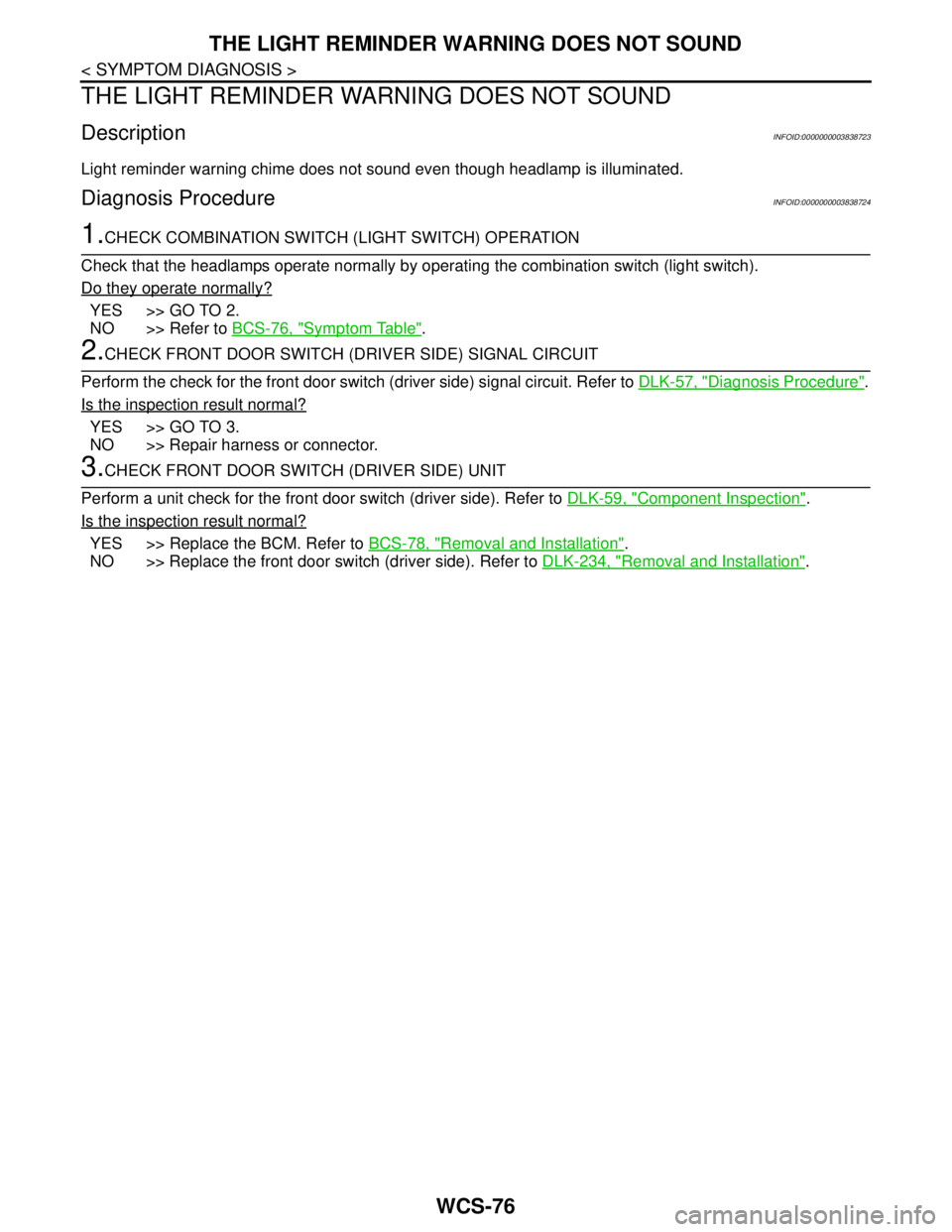
THE LIGHT REMINDER WARNING DOES NOT SOUND
THE LIGHT REMINDER WARNING DOES NOT SOUND
DescriptionINFOID:0000000003838723
Light reminder warning chime does not sound even though headlamp is illuminated.
Diagnosis ProcedureINFOID:0000000003838724
1.CHECK COMBINATION SWITCH (LIGHT SWITCH) OPERATION
Check that the headlamps operate normally by operating the combination switch (light switch).
Do they operate normally?
YES >> GO TO 2.
NO >> Refer to BCS-76, "
Symptom Table".
2.CHECK FRONT DOOR SWITCH (DRIVER SIDE) SIGNAL CIRCUIT
Perform the check for the front door switch (driver side) signal circuit. Refer to DLK-57, "
Diagnosis Procedure".
Is the inspection result normal?
YES >> GO TO 3.
NO >> Repair harness or connector.
3.CHECK FRONT DOOR SWITCH (DRIVER SIDE) UNIT
Perform a unit check for the front door switch (driver side). Refer to DLK-59, "
Component Inspection".
Is the inspection result normal?
YES >> Replace the BCM. Refer to BCS-78, "Removal and Installation".
NO >> Replace the front door switch (driver side). Refer to DLK-234, "
Removal and Installation".
Page 5013 of 5121

WW-1
DRIVER CONTROLS
C
D
E
F
G
H
I
J
K
M
SECTION WW
A
B
WW
N
O
P
CONTENTS
WIPER & WASHER
BASIC INSPECTION ....................................3
DIAGNOSIS AND REPAIR WORKFLOW ..........3
Work Flow .................................................................3
FUNCTION DIAGNOSIS ...............................5
FRONT WIPER AND WASHER SYSTEM ..........5
System Diagram ........................................................5
System Description ...................................................5
Component Parts Location ........................................8
Component Description ............................................8
HEADLAMP WASHER SYSTEM .......................10
System Diagram ......................................................10
System Description .................................................10
Component Parts Location ......................................11
Component Description ..........................................11
DIAGNOSIS SYSTEM (BCM) ............................12
COMMON ITEM .........................................................12
COMMON ITEM : CONSULT-III Function (BCM -
COMMON ITEM) .....................................................
12
WIPER .......................................................................13
WIPER : CONSULT-III Function (BCM - WIPER) ....13
DIAGNOSIS SYSTEM (IPDM E/R) .....................15
Diagnosis Description .............................................15
CONSULT-III Function (IPDM E/R) .........................17
COMPONENT DIAGNOSIS .........................20
WIPER AND WASHER FUSE, FUSIBLE LINK
....
20
Description ..............................................................20
Diagnosis Procedure ...............................................20
POWER SUPPLY AND GROUND CIRCUIT ......21
BCM (BODY CONTROL MODULE) ..........................21
BCM (BODY CONTROL MODULE) : Diagnosis
Procedure ................................................................
21
IPDM E/R (INTELLIGENT POWER DISTRIBU-
TION MODULE ENGINE ROOM) ..............................
21
IPDM E/R (INTELLIGENT POWER DISTRIBU-
TION MODULE ENGINE ROOM) : Diagnosis Pro-
cedure ......................................................................
21
FRONT WIPER MOTOR LO CIRCUIT ..............23
Component Function Check ....................................23
Diagnosis Procedure ...............................................23
FRONT WIPER MOTOR HI CIRCUIT ...............25
Component Function Check ....................................25
Diagnosis Procedure ...............................................25
FRONT WIPER AUTO STOP SIGNAL CIR-
CUIT ..................................................................
27
Component Function Check ....................................27
Diagnosis Procedure ...............................................27
FRONT WIPER MOTOR GROUND CIRCUIT ...29
Diagnosis Procedure ...............................................29
WASHER SWITCH ............................................30
Description ...............................................................30
Component Inspection .............................................30
HEADLAMP WASHER RELAY ........................31
Component Inspection .............................................31
HEADLAMP WASHER CIRCUIT ......................32
Component Function Check ....................................32
Diagnosis Procedure ...............................................32
FRONT WIPER AND WASHER SYSTEM ........35
Wiring Diagram - FRONT WIPER AND WASHER
SYSTEM - ................................................................
35
HEADLAMP WASHER SYSTEM ......................39
Wiring Diagram -HEADLAMP WASHER SYS-
TEM- ........................................................................
39
Page 5014 of 5121

WW-2
ECU DIAGNOSIS ........................................42
BCM (BODY CONTROL MODULE) ..................42
Reference Value .....................................................42
Wiring Diagram - BCM - .........................................65
Fail-safe ..................................................................71
DTC Inspection Priority Chart ..............................73
DTC Index ..............................................................74
IPDM E/R (INTELLIGENT POWER DISTRI-
BUTION MODULE ENGINE ROOM) .................
76
Reference Value .....................................................76
Wiring Diagram - IPDM E/R - ..................................84
Fail-safe ..................................................................87
DTC Index ..............................................................89
SYMPTOM DIAGNOSIS .............................90
FRONT WIPER AND WASHER SYSTEM
SYMPTOMS .......................................................
90
Symptom Table ......................................................90
NORMAL OPERATING CONDITION ................92
Description ..............................................................92
FRONT WIPER DOES NOT OPERATE ............93
Description ..............................................................93
Diagnosis Procedure ..............................................93
HEADLAMP WASHER DOES NOT OPER-
ATE ....................................................................
95
Description ..............................................................95
Diagnosis Procedure ..............................................95
PRECAUTION .............................................96
PRECAUTIONS .................................................96
Precaution for Supplemental Restraint System
(SRS) "AIR BAG" and "SEAT BELT PRE-TEN-
SIONER" .................................................................
96
Precaution for Procedure without Cowl Top Cover ...96
ON-VEHICLE REPAIR ...............................97
HEADLAMP WASHER NOZZLE AND TUBE ...97
Exploded View ........................................................97
Hydraulic Layout .....................................................97
Removal and Installation .........................................97
Inspection ................................................................98
WASHER TANK ................................................99
Exploded View ........................................................99
Removal and Installation .........................................99
WASHER PUMP ...............................................100
Exploded View ......................................................100
Removal and Installation .......................................100
HEADLAMP WASHER PUMP .........................101
Exploded View ......................................................101
Removal and Installation .......................................101
FRONT WASHER NOZZLE AND TUBE ..........102
Hydraulic Layout ...................................................102
Removal and Installation .......................................102
Inspection and Adjustment ....................................102
FRONT WIPER ARM ........................................105
Exploded View ......................................................105
Removal and Installation .......................................105
Adjustment ............................................................105
FRONT WIPER DRIVE ASSEMBLY ................107
Exploded View ......................................................107
Removal and Installation .......................................107
Disassembly and Assembly ..................................108
FRONT WIPER AND WASHER SWITCH ........109
Exploded View ......................................................109
Page 5022 of 5121

WW-10
< FUNCTION DIAGNOSIS >
HEADLAMP WASHER SYSTEM
HEADLAMP WASHER SYSTEM
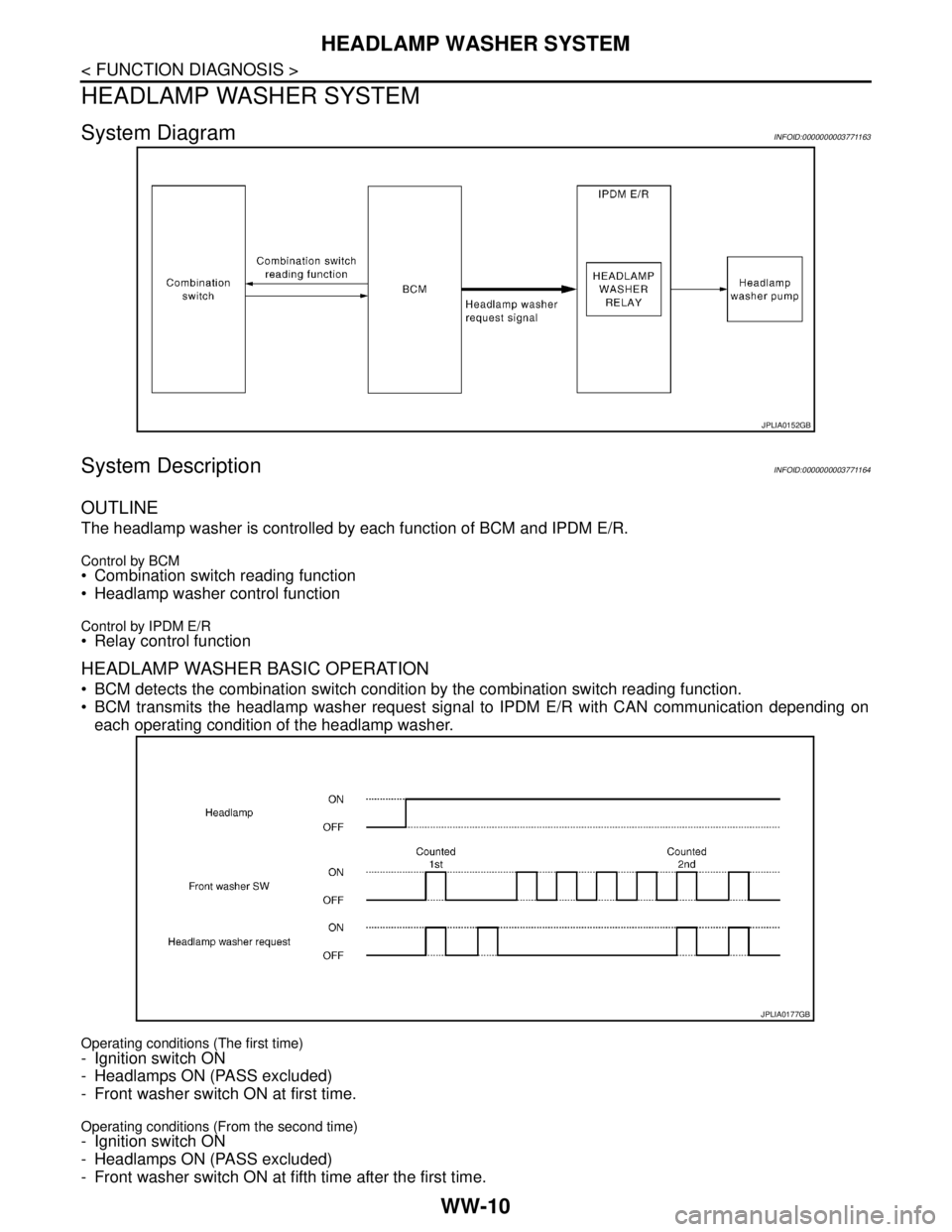
System DiagramINFOID:0000000003771163
System DescriptionINFOID:0000000003771164
OUTLINE
The headlamp washer is controlled by each function of BCM and IPDM E/R.
Control by BCM Combination switch reading function
Headlamp washer control function
Control by IPDM E/R Relay control function
HEADLAMP WASHER BASIC OPERATION
BCM detects the combination switch condition by the combination switch reading function.
BCM transmits the headlamp washer request signal to IPDM E/R with CAN communication depending on
each operating condition of the headlamp washer.
Operating conditions (The first time)
- Ignition switch ON
- Headlamps ON (PASS excluded)
- Front washer switch ON at first time.
Operating conditions (From the second time)- Ignition switch ON
- Headlamps ON (PASS excluded)
- Front washer switch ON at fifth time after the first time.
JPLIA0152GB
JPLIA0177GB
Page 5023 of 5121

HEADLAMP WASHER SYSTEM
WW-11
< FUNCTION DIAGNOSIS >
C
D
E
F
G
H
I
J
K
MA
B
WW
N
O
P
IPDM E/R turns ON/OFF the headlamp washer relay by receiving the headlamp washer request signal, and
controls the headlamp washer twice.
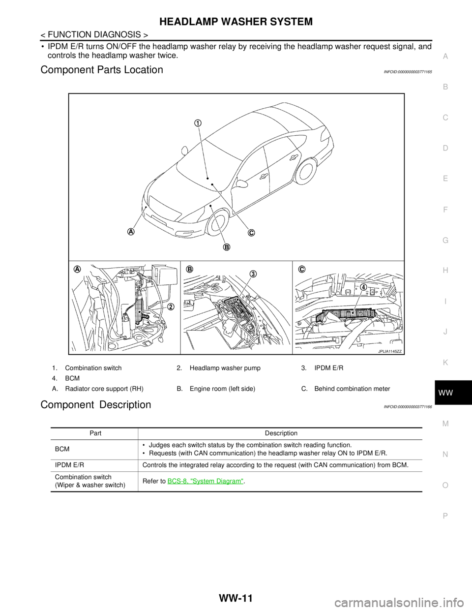
Component Parts LocationINFOID:0000000003771165
Component DescriptionINFOID:0000000003771166
1. Combination switch 2. Headlamp washer pump 3. IPDM E/R
4. BCM
A. Radiator core support (RH) B. Engine room (left side) C. Behind combination meter
JPLIA1145ZZ
Part Description
BCM Judges each switch status by the combination switch reading function.
Requests (with CAN communication) the headlamp washer relay ON to IPDM E/R.
IPDM E/R Controls the integrated relay according to the request (with CAN communication) from BCM.
Combination switch
(Wiper & washer switch)Refer to BCS-8, "
System Diagram".
Page 5026 of 5121
![NISSAN TEANA 2008 Service Manual WW-14
< FUNCTION DIAGNOSIS >
DIAGNOSIS SYSTEM (BCM)
DATA MONITOR
ACTIVE TEST
Monitor Item
[Unit]Description
PUSH SW
[Off/On]The switch status input from push-button ignition switch.
VEH SPEED 1
[km/h] NISSAN TEANA 2008 Service Manual WW-14
< FUNCTION DIAGNOSIS >
DIAGNOSIS SYSTEM (BCM)
DATA MONITOR
ACTIVE TEST
Monitor Item
[Unit]Description
PUSH SW
[Off/On]The switch status input from push-button ignition switch.
VEH SPEED 1
[km/h]](/manual-img/5/57391/w960_57391-5025.png)
WW-14
< FUNCTION DIAGNOSIS >
DIAGNOSIS SYSTEM (BCM)
DATA MONITOR
ACTIVE TEST
Monitor Item
[Unit]Description
PUSH SW
[Off/On]The switch status input from push-button ignition switch.
VEH SPEED 1
[km/h]Displays the value of the vehicle speed signal received from combination meter with CAN communication.
FR WIPER HI
[Off/On]
Status of each switch judged by BCM using the combination switch reading function FR WIPER LOW
[Off/On]
FR WASHER SW
[Off/On]
FR WIPER INT
[Off/On]
FR WIPER STOP
[Off/On]Displays the status of the front wiper stop position signal received from IPDM E/R with CAN communication.
INT VOLUME
[1 − 7] Status of each switch judged by BCM using the combination switch reading function
H/L WASH SW
[Off/On]Status of the switch input from headlamp washer switch
Test item Operation Description
FRONT WIPERHiTransmits the front wiper request signal (HI) to IPDM E/R with CAN communication to
operate the front wiper HI operation.
LoTransmits the front wiper request signal (LO) to IPDM E/R with CAN communication to
operate the front wiper LO operation.
INTTransmits the front wiper request signal (INT) to IPDM E/R with CAN communication to
operate the front wiper INT operation.
Off Stops transmitting the front wiper request signal to stop the front wiper operation.
HEADLAMP WASHER OnTransmits the headlamp washer request signal to IPDM E/R with CAN communication to
operate the headlamp washer operation.
Page 5027 of 5121

DIAGNOSIS SYSTEM (IPDM E/R)
WW-15
< FUNCTION DIAGNOSIS >
C
D
E
F
G
H
I
J
K
MA
B
WW
N
O
P
DIAGNOSIS SYSTEM (IPDM E/R)
Diagnosis DescriptionINFOID:0000000003941292
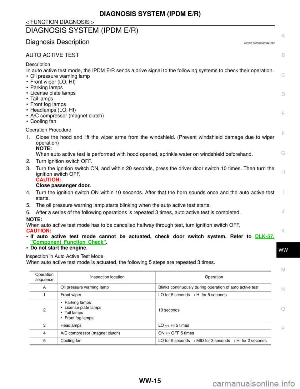
AUTO ACTIVE TEST
Description
In auto active test mode, the IPDM E/R sends a drive signal to the following systems to check their operation.
Oil pressure warning lamp
Front wiper (LO, HI)
Parking lamps
License plate lamps
Tail lamps
Front fog lamps
Headlamps (LO, HI)
A/C compressor (magnet clutch)
Cooling fan
Operation Procedure
1. Close the hood and lift the wiper arms from the windshield. (Prevent windshield damage due to wiper
operation)
NOTE:
When auto active test is performed with hood opened, sprinkle water on windshield beforehand.
2. Turn ignition switch OFF.
3. Turn the ignition switch ON, and within 20 seconds, press the driver door switch 10 times. Then turn the
ignition switch OFF.
CAUTION:
Close passenger door.
4. Turn the ignition switch ON within 10 seconds. After that the horn sounds once and the auto active test
starts.
5. The oil pressure warning lamp starts blinking when the auto active test starts.
6. After a series of the following operations is repeated 3 times, auto active test is completed.
NOTE:
When auto active test mode has to be cancelled halfway through test, turn ignition switch OFF.
CAUTION:
• If auto active test mode cannot be actuated, check door switch system. Refer to DLK-57,
"ComponentFunctionCheck".
Do not start the engine.
Inspection in Auto Active Test Mode
When auto active test mode is actuated, the following 5 steps are repeated 3 times.
Operation
sequenceInspection location Operation
A Oil pressure warning lamp Blinks continuously during operation of auto active test
1 Front wiper LO for 5 seconds → HI for 5 seconds
2Parking lamps
License plate lamps
Tail lamps
Front fog lamps10 seconds
3 Headlamps LO ⇔ HI 5 times
4 A/C compressor (magnet clutch) ON ⇔ OFF 5 times
5 Cooling fan LO for 5 seconds → MID for 3 seconds → HI for 2 seconds