2008 NISSAN TEANA steering wheel
[x] Cancel search: steering wheelPage 4608 of 5121
![NISSAN TEANA 2008 Service Manual PRECAUTIONS
TM-135
< PRECAUTION >[CVT: RE0F09B]
C
E
F
G
H
I
J
K
L
MA
B
TM
N
O
P
PRECAUTION
PRECAUTIONS
Precaution for Supplemental Restraint System (SRS) "AIR BAG" and "SEAT BELT
PRE-TENSIONER"
INFOI](/manual-img/5/57391/w960_57391-4607.png "NISSAN TEANA 2008 Service Manual PRECAUTIONS
TM-135
< PRECAUTION >[CVT: RE0F09B]
C
E
F
G
H
I
J
K
L
MA
B
TM
N
O
P
PRECAUTION
PRECAUTIONS
Precaution for Supplemental Restraint System (SRS) \"AIR BAG\" and \"SEAT BELT
PRE-TENSIONER\"
INFOI")
PRECAUTIONS
TM-135
< PRECAUTION >[CVT: RE0F09B]
C
E
F
G
H
I
J
K
L
MA
B
TM
N
O
P
PRECAUTION
PRECAUTIONS
Precaution for Supplemental Restraint System (SRS) "AIR BAG" and "SEAT BELT
PRE-TENSIONER"
INFOID:0000000003897161
The Supplemental Restraint System such as “AIR BAG” and “SEAT BELT PRE-TENSIONER”, used along
with a front seat belt, helps to reduce the risk or severity of injury to the driver and front passenger for certain
types of collision. Information necessary to service the system safely is included in the “SRS AIRBAG” and
“SEAT BELT” of this Service Manual.
WARNING:
To avoid rendering the SRS inoperative, which could increase the risk of personal injury or death in
the event of a collision which would result in air bag inflation, all maintenance must be performed by
an authorized NISSAN/INFINITI dealer.
Improper maintenance, including incorrect removal and installation of the SRS, can lead to personal
injury caused by unintentional activation of the system. For removal of Spiral Cable and Air Bag
Module, see the “SRS AIRBAG”.
Never use electrical test equipment on any circuit related to the SRS unless instructed to in this Ser-
vice Manual. SRS wiring harnesses can be identified by yellow and/or orange harnesses or harness
connectors.
Precaution Necessary for Steering Wheel Rotation after Battery Disconnect
INFOID:0000000003897162
NOTE:
Before removing and installing any control units, first turn the push-button ignition switch to the LOCK posi-
tion, then disconnect both battery cables.
After finishing work, confirm that all control unit connectors are connected properly, then re-connect both
battery cables.
Always use CONSULT-III to perform self-diagnosis as a part of each function inspection after finishing work.
If a DTC is detected, perform trouble diagnosis according to self-diagnosis results.
This vehicle is equipped with a push-button ignition switch and a steering lock unit.
If the battery is disconnected or discharged, the steering wheel will lock and cannot be turned.
If turning the steering wheel is required with the battery disconnected or discharged, follow the procedure
below before starting the repair operation.
OPERATION PROCEDURE
1. Connect both battery cables.
NOTE:
Supply power using jumper cables if battery is discharged.
2. Turn the push-button ignition switch to ACC position.
(At this time, the steering lock will be released.)
3. Disconnect both battery cables. The steering lock will remain released with both battery cables discon-
nected and the steering wheel can be turned.
4. Perform the necessary repair operation.
5. When the repair work is completed, re-connect both battery cables. With the brake pedal released, turn
the push-button ignition switch from ACC position to ON position, then to LOCK position. (The steering
wheel will lock when the push-button ignition switch is turned to LOCK position.)
6. Perform self-diagnosis check of all control units using CONSULT-III.
Page 4770 of 5121
![NISSAN TEANA 2008 Service Manual PRECAUTIONS
TM-297
< PRECAUTION >[CVT: RE0F10A]
C
E
F
G
H
I
J
K
L
MA
B
TM
N
O
P
PRECAUTION
PRECAUTIONS
Precaution for Supplemental Restraint System (SRS) "AIR BAG" and "SEAT BELT
PRE-TENSIONER"
INFOI](/manual-img/5/57391/w960_57391-4769.png "NISSAN TEANA 2008 Service Manual PRECAUTIONS
TM-297
< PRECAUTION >[CVT: RE0F10A]
C
E
F
G
H
I
J
K
L
MA
B
TM
N
O
P
PRECAUTION
PRECAUTIONS
Precaution for Supplemental Restraint System (SRS) \"AIR BAG\" and \"SEAT BELT
PRE-TENSIONER\"
INFOI")
PRECAUTIONS
TM-297
< PRECAUTION >[CVT: RE0F10A]
C
E
F
G
H
I
J
K
L
MA
B
TM
N
O
P
PRECAUTION
PRECAUTIONS
Precaution for Supplemental Restraint System (SRS) "AIR BAG" and "SEAT BELT
PRE-TENSIONER"
INFOID:0000000003901473
The Supplemental Restraint System such as “AIR BAG” and “SEAT BELT PRE-TENSIONER”, used along
with a front seat belt, helps to reduce the risk or severity of injury to the driver and front passenger for certain
types of collision. Information necessary to service the system safely is included in the “SRS AIRBAG” and
“SEAT BELT” of this Service Manual.
WARNING:
To avoid rendering the SRS inoperative, which could increase the risk of personal injury or death in
the event of a collision which would result in air bag inflation, all maintenance must be performed by
an authorized NISSAN/INFINITI dealer.
Improper maintenance, including incorrect removal and installation of the SRS, can lead to personal
injury caused by unintentional activation of the system. For removal of Spiral Cable and Air Bag
Module, see the “SRS AIRBAG”.
Never use electrical test equipment on any circuit related to the SRS unless instructed to in this Ser-
vice Manual. SRS wiring harnesses can be identified by yellow and/or orange harnesses or harness
connectors.
Precaution Necessary for Steering Wheel Rotation after Battery Disconnect
INFOID:0000000003901477
NOTE:
Before removing and installing any control units, first turn the push-button ignition switch to the LOCK posi-
tion, then disconnect both battery cables.
After finishing work, confirm that all control unit connectors are connected properly, then re-connect both
battery cables.
Always use CONSULT-III to perform self-diagnosis as a part of each function inspection after finishing work.
If a DTC is detected, perform trouble diagnosis according to self-diagnosis results.
This vehicle is equipped with a push-button ignition switch and a steering lock unit.
If the battery is disconnected or discharged, the steering wheel will lock and cannot be turned.
If turning the steering wheel is required with the battery disconnected or discharged, follow the procedure
below before starting the repair operation.
OPERATION PROCEDURE
1. Connect both battery cables.
NOTE:
Supply power using jumper cables if battery is discharged.
2. Turn the push-button ignition switch to ACC position.
(At this time, the steering lock will be released.)
3. Disconnect both battery cables. The steering lock will remain released with both battery cables discon-
nected and the steering wheel can be turned.
4. Perform the necessary repair operation.
5. When the repair work is completed, re-connect both battery cables. With the brake pedal released, turn
the push-button ignition switch from ACC position to ON position, then to LOCK position. (The steering
wheel will lock when the push-button ignition switch is turned to LOCK position.)
6. Perform self-diagnosis check of all control units using CONSULT-III.
Page 4812 of 5121

VTL-1
VENTILATION, HEATER & AIR CONDITIONER
C
DE
F
G H
J
K L
M
SECTION VTL
A
B
VTL
N
O P
CONTENTS
VENTILATION SYSTEM
WITHOUT 7 INCH DISPLAY
FUNCTION DIAGNOSIS .. .............................
5
SWITCHES AND THEIR CONTROL FUNC-
TION ............................................................... .....
5
System Description ............................................. ......5
AIR DISTRIBUTION ............................................6
System Description ............................................. ......6
PRECAUTION ...............................................7
PRECAUTIONS .............................................. .....7
Precaution for Supplemental Restraint System
(SRS) "AIR BAG" and "SEAT BELT PRE-TEN-
SIONER" ............................................................. ......
7
Precaution Necessary for Steering Wheel Rota-
tion after Battery Disconnect .....................................
7
Precaution for Procedure without Cowl Top Cover ......8
Precautions For Xenon Headlamp Service ...............8
Working with HFC-134a (R-134a) .............................8
General Refrigerant Precaution ................................8
Refrigerant Connection .............................................9
Service Equipment ..................................................11
COMPRESSOR .............................................. ....14
General Precautions ........................................... ....14
FLUORESCENT LEAK DETECTOR .................15
General Precautions ........................................... ....15
PREPARATION ...........................................16
PREPARATION .............................................. ....16
Special Service Tool ........................................... ....16
Commercial Service Tool ........................................18
Sealant or/and Lubricant .........................................18
ON-VEHICLE MAINTENANCE ....................20
AIR CONDITIONER FILTER .......................... ....20
Exploded View .................................................... ....20
Removal and Installation ..................................... ....20
Replacement ...........................................................20
ON-VEHICLE REPAIR .................................21
A/C CONTROL ..................................................21
Exploded View ..................................................... ....21
Removal and Installation .........................................21
A/C DISPLAY ....................................................22
Exploded View .........................................................22
Removal and Installation .........................................22
A/C AUTO AMP. ...............................................23
Exploded View .........................................................23
Removal and Installation .........................................23
AMBIENT SENSOR ..........................................24
Exploded View .........................................................24
Removal and Installation .........................................24
IN-VEHICLE SENSOR ......................................25
Exploded View .........................................................25
Removal and Installation .........................................25
SUNLOAD SENSOR .........................................26
Exploded View .........................................................26
Removal and Installation .........................................26
INTAKE SENSOR .............................................27
Exploded View .........................................................27
Removal and Installation .........................................28
BLOWER UNIT .................................................29
Exploded View .........................................................29
Removal and Installation .........................................30
BLOWER MOTOR ............................................32
Exploded View .........................................................32
Removal and Installation .........................................32
INTAKE DOOR MOTOR ...................................33
Exploded View .........................................................33
Page 4813 of 5121

VTL-2
Removal and Installation ........................................33
HEATER & COOLING UNIT ASSEMBLY .........35
Exploded View ........................................................35
Removal and Installation ........................................37
MODE DOOR MOTOR ......................................40
Exploded View ........................................................40
Removal and Installation ........................................40
AIR MIX DOOR MOTOR ....................................41
Exploded View ........................................................41
Removal and Installation ........................................41
HEATER CORE .................................................43
Exploded View ........................................................43
Removal and Installation ........................................44
DUCT AND GRILLE ..........................................45
CENTER VENTILATOR GRILLE ..............................45
CENTER VENTILATOR GRILLE : Exploded View ...45
CENTER VENTILATOR GRILLE : Removal and
Installation ..............................................................
45
SIDE VENTILATOR GRILLE ....................................45
SIDE VENTILATOR GRILLE : Exploded View .......46
SIDE VENTILATOR GRILLE : Removal and In-
stallation .................................................................
46
SIDE DEFROSTER GRILLE .....................................46
SIDE DEFROSTER GRILLE : Exploded View ........47
SIDE DEFROSTER GRILLE : Removal and In-
stallation .................................................................
47
VENTILATOR DUCT .................................................47
VENTILATOR DUCT : Exploded View ...................48
VENTILATOR DUCT : Removal and Installation ....48
SIDE DEFROSTER NOZZLE ....................................49
SIDE DEFROSTER NOZZLE : Exploded View ......49
SIDE DEFROSTER NOZZLE : Removal and In-
stallation .................................................................
49
DEFROSTER NOZZLE .............................................50
DEFROSTER NOZZLE : Exploded View ................50
DEFROSTER NOZZLE : Removal and Installation
...
51
REAR VENTILATOR GRILLE ..................................51
REAR VENTILATOR GRILLE : Exploded View ......52
REAR VENTILATOR GRILLE : Removal and In-
stallation .................................................................
52
REAR VENTILATOR DUCT 1 ...................................52
REAR VENTILATOR DUCT 1 : Exploded View .....53
REAR VENTILATOR DUCT 1 : Removal and In-
stallation .................................................................
53
REAR VENTILATOR DUCT 2 ...................................53
REAR VENTILATOR DUCT 2 : Exploded View .....54
REAR VENTILATOR DUCT 2 : Removal and In-
stallation .................................................................
54
REAR FOOT DUCT 1 ................................................54
REAR FOOT DUCT 1 : Exploded View ..................55
REAR FOOT DUCT 1 : Removal and Installation ...55
REAR FOOT DUCT 2 ................................................56
REAR FOOT DUCT 2 : Exploded View ..................56
REAR FOOT DUCT 2 : Removal and Installation ...56
REAR FOOT DUCT 3 ................................................57
REAR FOOT DUCT 3 : Exploded View ..................58
REAR FOOT DUCT 3 : Removal and Installation ...58
FOOT DUCT ..............................................................59
FOOT DUCT : Exploded View ................................59
FOOT DUCT : Removal and Installation .................60
WITH 7 INCH DISPLAY
FUNCTION DIAGNOSIS ............................
61
SWITCHES AND THEIR CONTROL FUNC-
TION ...................................................................
61
WITHOUT INTELLIGENT AIR CONDITIONER
SYSTEM ....................................................................
61
WITHOUT INTELLIGENT AIR CONDITIONER
SYSTEM : System Description ...............................
61
WITH INTELLIGENT AIR CONDITIONER SYS-
TEM ...........................................................................
62
WITH INTELLIGENT AIR CONDITIONER SYS-
TEM : System Description ......................................
62
AIR DISTRIBUTION ..........................................63
System Description .................................................63
PRECAUTION ............................................64
PRECAUTIONS .................................................64
Precaution for Supplemental Restraint System
(SRS) "AIR BAG" and "SEAT BELT PRE-TEN-
SIONER" .................................................................
64
Precaution Necessary for Steering Wheel Rota-
tion after Battery Disconnect ...................................
64
Precaution for Procedure without Cowl Top Cover ...65
Precautions For Xenon Headlamp Service .............65
Working with HFC-134a (R-134a) ...........................65
General Refrigerant Precaution ..............................65
Refrigerant Connection ...........................................66
Service Equipment ..................................................68
COMPRESSOR .................................................71
General Precautions ...............................................71
FLUORESCENT LEAK DETECTOR .................72
General Precautions ...............................................72
PREPARATION ..........................................73
PREPARATION .................................................73
Special Service Tool ...............................................73
Commercial Service Tool ........................................75
Sealant or/and Lubricant .........................................75
Page 4818 of 5121
![NISSAN TEANA 2008 Service Manual PRECAUTIONS
VTL-7
< PRECAUTION >[WITHOUT 7 INCH DISPLAY]
C
D
E
F
G
H
J
K
L
MA
B
VTL
N
O
P
PRECAUTION
PRECAUTIONS
Precaution for Supplemental Restraint System (SRS) "AIR BAG" and "SEAT BELT
PRE-TENSIO](/manual-img/5/57391/w960_57391-4817.png "NISSAN TEANA 2008 Service Manual PRECAUTIONS
VTL-7
< PRECAUTION >[WITHOUT 7 INCH DISPLAY]
C
D
E
F
G
H
J
K
L
MA
B
VTL
N
O
P
PRECAUTION
PRECAUTIONS
Precaution for Supplemental Restraint System (SRS) \"AIR BAG\" and \"SEAT BELT
PRE-TENSIO")
PRECAUTIONS
VTL-7
< PRECAUTION >[WITHOUT 7 INCH DISPLAY]
C
D
E
F
G
H
J
K
L
MA
B
VTL
N
O
P
PRECAUTION
PRECAUTIONS
Precaution for Supplemental Restraint System (SRS) "AIR BAG" and "SEAT BELT
PRE-TENSIONER"
INFOID:0000000003845339
The Supplemental Restraint System such as “AIR BAG” and “SEAT BELT PRE-TENSIONER”, used along
with a front seat belt, helps to reduce the risk or severity of injury to the driver and front passenger for certain
types of collision. Information necessary to service the system safely is included in the “SRS AIRBAG” and
“SEAT BELT” of this Service Manual.
WARNING:
• To avoid rendering the SRS inoperative, which could increase the risk of personal injury or death in
the event of a collision which would result in air bag inflation, all maintenance must be performed by
an authorized NISSAN/INFINITI dealer.
Improper maintenance, including incorrect removal and installation of the SRS, can lead to personal
injury caused by unintentional activation of the system. For removal of Spiral Cable and Air Bag
Module, see the “SRS AIRBAG”.
Never use electrical test equipment on any circuit related to the SRS unless instructed to in this Ser-
vice Manual. SRS wiring harnesses can be identified by yellow and/or orange harnesses or harness
connectors.
Precaution Necessary for Steering Wheel Rotation after Battery Disconnect
INFOID:0000000003845340
NOTE:
Before removing and installing any control units, first turn the push-button ignition switch to the LOCK posi-
tion, then disconnect both battery cables.
After finishing work, confirm that all control unit connectors are connected properly, then re-connect both
battery cables.
Always use CONSULT-III to perform self-diagnosis as a part of each function inspection after finishing work.
If a DTC is detected, perform trouble diagnosis according to self-diagnosis results.
This vehicle is equipped with a push-button ignition switch and a steering lock unit.
If the battery is disconnected or discharged, the steering wheel will lock and cannot be turned.
If turning the steering wheel is required with the battery disconnected or discharged, follow the procedure
below before starting the repair operation.
OPERATION PROCEDURE
1. Connect both battery cables.
NOTE:
Supply power using jumper cables if battery is discharged.
2. Turn the push-button ignition switch to ACC position.
(At this time, the steering lock will be released.)
3. Disconnect both battery cables. The steering lock will remain released with both battery cables discon-
nected and the steering wheel can be turned.
4. Perform the necessary repair operation.
5. When the repair work is completed, re-connect both battery cables. With the brake pedal released, turn
the push-button ignition switch from ACC position to ON position, then to LOCK position. (The steering
wheel will lock when the push-button ignition switch is turned to LOCK position.)
6. Perform self-diagnosis check of all control units using CONSULT-III.
Page 4875 of 5121
![NISSAN TEANA 2008 Service Manual VTL-64
< PRECAUTION >[WITH 7 INCH DISPLAY]
PRECAUTIONS
PRECAUTION
PRECAUTIONS
Precaution for Supplemental Restraint System (SRS) "AIR BAG" and "SEAT BELT
PRE-TENSIONER"
INFOID:0000000003894443
The Su](/manual-img/5/57391/w960_57391-4874.png "NISSAN TEANA 2008 Service Manual VTL-64
< PRECAUTION >[WITH 7 INCH DISPLAY]
PRECAUTIONS
PRECAUTION
PRECAUTIONS
Precaution for Supplemental Restraint System (SRS) \"AIR BAG\" and \"SEAT BELT
PRE-TENSIONER\"
INFOID:0000000003894443
The Su")
VTL-64
< PRECAUTION >[WITH 7 INCH DISPLAY]
PRECAUTIONS
PRECAUTION
PRECAUTIONS
Precaution for Supplemental Restraint System (SRS) "AIR BAG" and "SEAT BELT
PRE-TENSIONER"
INFOID:0000000003894443
The Supplemental Restraint System such as “AIR BAG” and “SEAT BELT PRE-TENSIONER”, used along
with a front seat belt, helps to reduce the risk or severity of injury to the driver and front passenger for certain
types of collision. Information necessary to service the system safely is included in the “SRS AIRBAG” and
“SEAT BELT” of this Service Manual.
WARNING:
To avoid rendering the SRS inoperative, which could increase the risk of personal injury or death in
the event of a collision which would result in air bag inflation, all maintenance must be performed by
an authorized NISSAN/INFINITI dealer.
Improper maintenance, including incorrect removal and installation of the SRS, can lead to personal
injury caused by unintentional activation of the system. For removal of Spiral Cable and Air Bag
Module, see the “SRS AIRBAG”.
Do not use electrical test equipment on any circuit related to the SRS unless instructed to in this
Service Manual. SRS wiring harnesses can be identified by yellow and/or orange harnesses or har-
ness connectors.
Precaution Necessary for Steering Wheel Rotation after Battery Disconnect
INFOID:0000000003894445
NOTE:
Before removing and installing any control units, first turn the push-button ignition switch to the LOCK posi-
tion, then disconnect both battery cables.
After finishing work, confirm that all control unit connectors are connected properly, then re-connect both
battery cables.
Always use CONSULT-III to perform self-diagnosis as a part of each function inspection after finishing work.
If a DTC is detected, perform trouble diagnosis according to self-diagnosis results.
This vehicle is equipped with a push-button ignition switch and a steering lock unit.
If the battery is disconnected or discharged, the steering wheel will lock and cannot be turned.
If turning the steering wheel is required with the battery disconnected or discharged, follow the procedure
below before starting the repair operation.
OPERATION PROCEDURE
1. Connect both battery cables.
NOTE:
Supply power using jumper cables if battery is discharged.
2. Turn the push-button ignition switch to ACC position.
(At this time, the steering lock will be released.)
3. Disconnect both battery cables. The steering lock will remain released with both battery cables discon-
nected and the steering wheel can be turned.
4. Perform the necessary repair operation.
5. When the repair work is completed, re-connect both battery cables. With the brake pedal released, turn
the push-button ignition switch from ACC position to ON position, then to LOCK position. (The steering
wheel will lock when the push-button ignition switch is turned to LOCK position.)
6. Perform self-diagnosis check of all control units using CONSULT-III.
Page 4986 of 5121
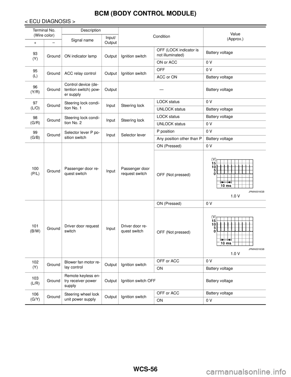
WCS-56
< ECU DIAGNOSIS >
BCM (BODY CONTROL MODULE)
93
(Y)Ground ON indicator lamp Output Ignition switchOFF (LOCK indicator is
not illuminated)Battery voltage
ON or ACC 0 V
95
(L)Ground ACC relay control Output Ignition switchOFF 0 V
ACC or ON Battery voltage
96
(Y/R)GroundControl device (de-
tention switch) pow-
er supplyOutput — Battery voltage
97
(L/O)GroundSteering lock condi-
tion No. 1Input Steering lockLOCK status 0 V
UNLOCK status Battery voltage
98
(G/R)GroundSteering lock condi-
tion No. 2Input Steering lockLOCK status Battery voltage
UNLOCK status 0 V
99
(G/B)GroundSelector lever P po-
sition switchInput Selector leverP position 0 V
Any position other than P Battery voltage
100
(P/L)GroundPassenger door re-
quest switchInputPassenger door
request switchON (Pressed) 0 V
OFF (Not pressed)
1.0 V
101
(B/W)GroundDriver door request
switchInputDriver door re-
quest switchON (Pressed) 0 V
OFF (Not pressed)
1.0 V
102
(Y)GroundBlower fan motor re-
lay controlOutput Ignition switchOFF or ACC 0 V
ON Battery voltage
103
(L/R)GroundRemote keyless en-
try receiver power
supplyOutput Ignition switch OFF Battery voltage
106
(G/Y)GroundSteering wheel lock
unit power supplyOutput Ignition switchOFF or ACC Battery voltage
ON 0 V Te r m i n a l N o .
(Wire color)Description
ConditionVa l u e
(Approx.)
Signal nameInput/
Output +–
JPMIA0016GB
JPMIA0016GB
Page 5069 of 5121
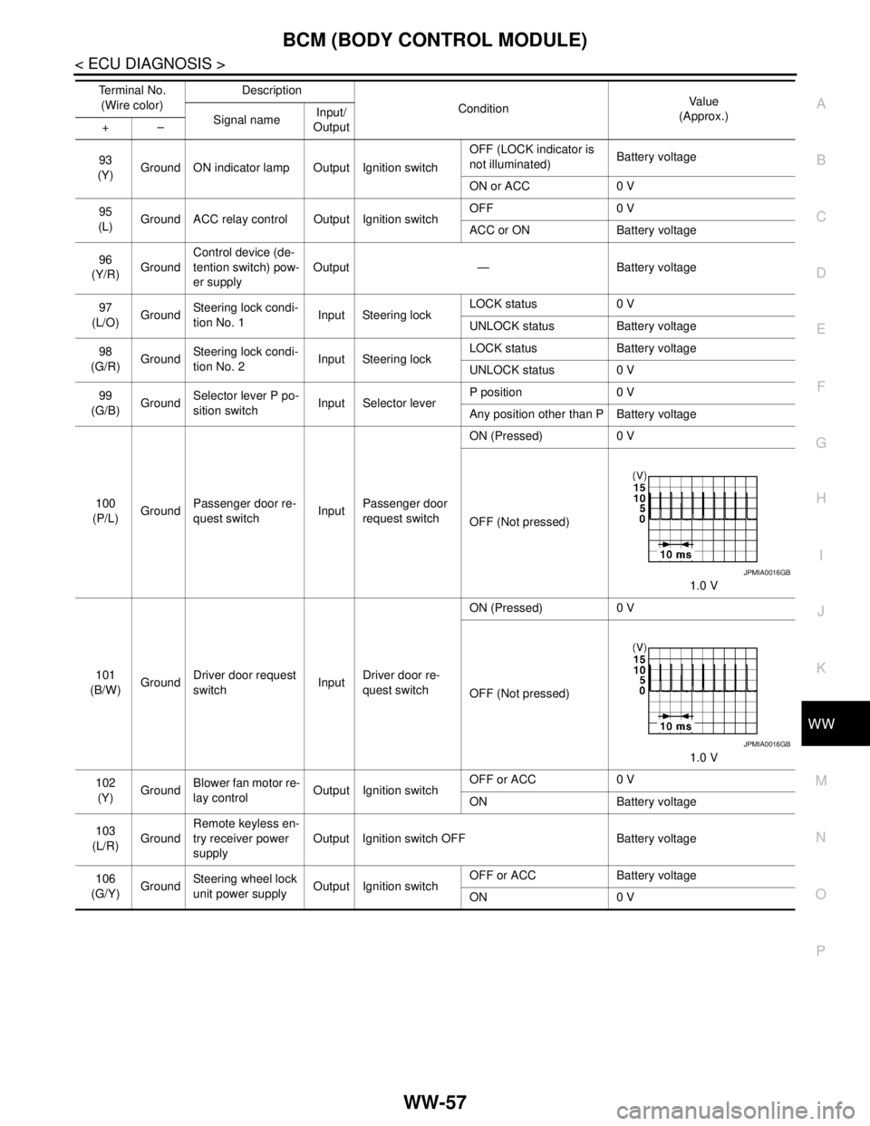
BCM (BODY CONTROL MODULE)
WW-57
< ECU DIAGNOSIS >
C
D
E
F
G
H
I
J
K
MA
B
WW
N
O
P
93
(Y)Ground ON indicator lamp Output Ignition switchOFF (LOCK indicator is
not illuminated)Battery voltage
ON or ACC 0 V
95
(L)Ground ACC relay control Output Ignition switchOFF 0 V
ACC or ON Battery voltage
96
(Y/R)GroundControl device (de-
tention switch) pow-
er supplyOutput — Battery voltage
97
(L/O)GroundSteering lock condi-
tion No. 1Input Steering lockLOCK status 0 V
UNLOCK status Battery voltage
98
(G/R)GroundSteering lock condi-
tion No. 2Input Steering lockLOCK status Battery voltage
UNLOCK status 0 V
99
(G/B)GroundSelector lever P po-
sition switchInput Selector leverP position 0 V
Any position other than P Battery voltage
100
(P/L)GroundPassenger door re-
quest switchInputPassenger door
request switchON (Pressed) 0 V
OFF (Not pressed)
1.0 V
101
(B/W)GroundDriver door request
switchInputDriver door re-
quest switchON (Pressed) 0 V
OFF (Not pressed)
1.0 V
102
(Y)GroundBlower fan motor re-
lay controlOutput Ignition switchOFF or ACC 0 V
ON Battery voltage
103
(L/R)GroundRemote keyless en-
try receiver power
supplyOutput Ignition switch OFF Battery voltage
106
(G/Y)GroundSteering wheel lock
unit power supplyOutput Ignition switchOFF or ACC Battery voltage
ON 0 V Te r m i n a l N o .
(Wire color)Description
ConditionVa l u e
(Approx.)
Signal nameInput/
Output +–
JPMIA0016GB
JPMIA0016GB