2008 NISSAN TEANA sensor
[x] Cancel search: sensorPage 1105 of 5121
CHG
POWER GENERATION VOLTAGE VARIABLE CONTROL SYSTEM
CHG-7
< FUNCTION DIAGNOSIS >
C
D
E
F
G
H
I
J
K
L B A
O
P N
POWER GENERATION VOLTAGE VARIABLE CONTROL SYSTEM
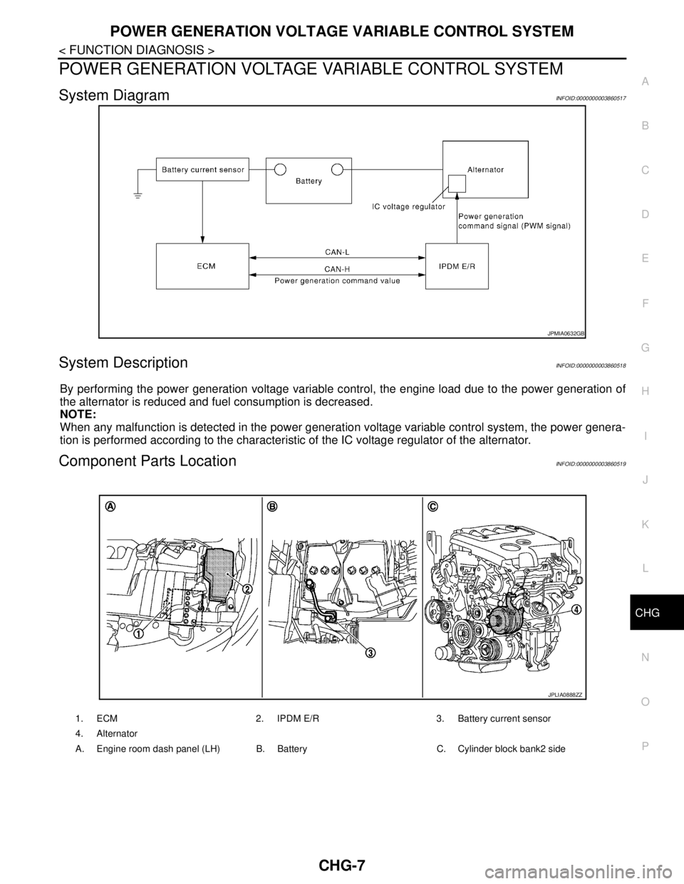
System DiagramINFOID:0000000003860517
System DescriptionINFOID:0000000003860518
By performing the power generation voltage variable control, the engine load due to the power generation of
the alternator is reduced and fuel consumption is decreased.
NOTE:
When any malfunction is detected in the power generation voltage variable control system, the power genera-
tion is performed according to the characteristic of the IC voltage regulator of the alternator.
Component Parts LocationINFOID:0000000003860519
JPMIA0632GB
1. ECM 2. IPDM E/R 3. Battery current sensor
4. Alternator
A. Engine room dash panel (LH) B. Battery C. Cylinder block bank2 side
JPLIA0888ZZ
Page 1106 of 5121

CHG-8
< FUNCTION DIAGNOSIS >
POWER GENERATION VOLTAGE VARIABLE CONTROL SYSTEM
Component Description
INFOID:0000000003860520
Component part Description
Battery current sensorBattery current sensor is installed to the battery cable at the neg-
ative terminal, and it detects the charging/discharging current of
the battery and sends the voltage signal to ECM according to the
current value.
ECMBattery current sensor detects the charging/discharging current of
the battery. ECM judges the battery condition based on this signal.
ECM judges whether to perform the power generation voltage
variable control according to the battery condition.
When performing the power generation voltage variable control,
ECM calculates the target power generation voltage according to
the battery condition and sends the calculated value as the power
generation command value to IPDM E/R.
IPDM E/RIPDM E/R converts the received power generation command val-
ue into the power generation command signal (PWM signal) and
sends it to the IC voltage regulator.
Alternator (IC voltage regulator)IC voltage regulator controls the power generation voltage by the
target power generation voltage based on the received power gen-
eration command signal.
When there is no power generation command signal, the alterna-
tor performs the normal power generation according to the char-
acteristic of the IC voltage regulator.
Page 1139 of 5121
CO-16
< ON-VEHICLE REPAIR >
COOLING FAN
COOLING FAN
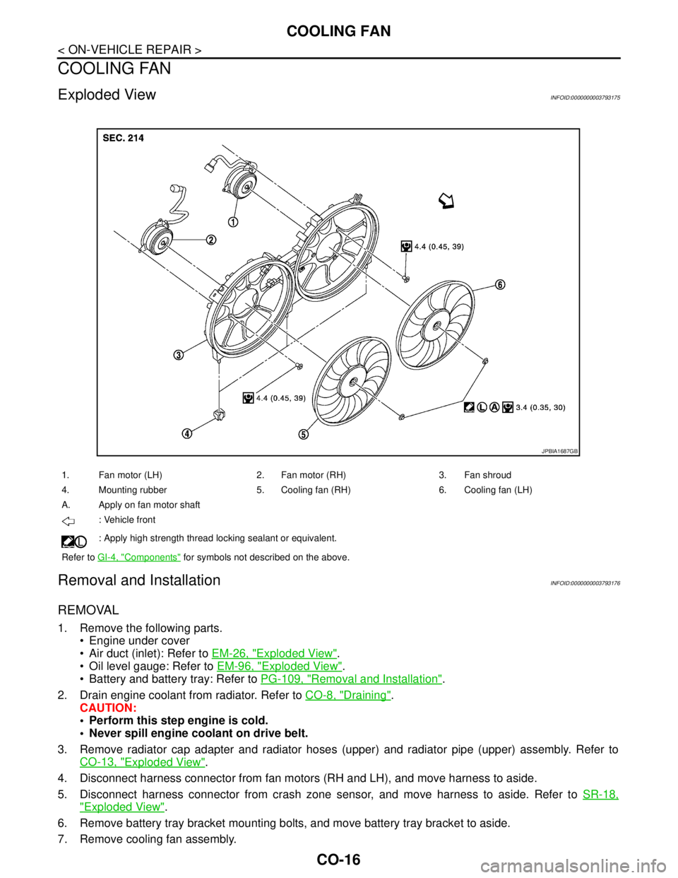
Exploded ViewINFOID:0000000003793175
Removal and InstallationINFOID:0000000003793176
REMOVAL
1. Remove the following parts.
Engine under cover
Air duct (inlet): Refer to EM-26, "
Exploded View".
Oil level gauge: Refer to EM-96, "
Exploded View".
Battery and battery tray: Refer to PG-109, "
Removal and Installation".
2. Drain engine coolant from radiator. Refer to CO-8, "
Draining".
CAUTION:
Perform this step engine is cold.
Never spill engine coolant on drive belt.
3. Remove radiator cap adapter and radiator hoses (upper) and radiator pipe (upper) assembly. Refer to
CO-13, "
Exploded View".
4. Disconnect harness connector from fan motors (RH and LH), and move harness to aside.
5. Disconnect harness connector from crash zone sensor, and move harness to aside. Refer to SR-18,
"Exploded View".
6. Remove battery tray bracket mounting bolts, and move battery tray bracket to aside.
7. Remove cooling fan assembly.
1. Fan motor (LH) 2. Fan motor (RH) 3. Fan shroud
4. Mounting rubber 5. Cooling fan (RH) 6. Cooling fan (LH)
A. Apply on fan motor shaft
: Vehicle front
: Apply high strength thread locking sealant or equivalent.
Refer to GI-4, "
Components" for symbols not described on the above.
JPBIA1687GB
Page 1148 of 5121
WATER OUTLET AND WATER PIPING
CO-25
< ON-VEHICLE REPAIR >
C
D
E
F
G
H
I
J
K
L
MA
CO
N
P O
WATER OUTLET AND WATER PIPING
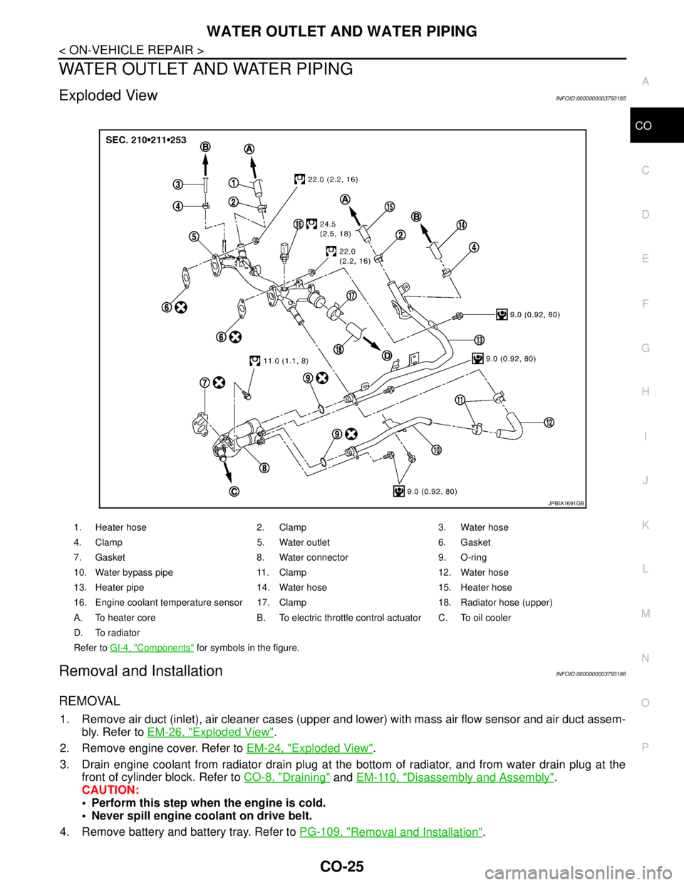
Exploded ViewINFOID:0000000003793185
Removal and InstallationINFOID:0000000003793186
REMOVAL
1. Remove air duct (inlet), air cleaner cases (upper and lower) with mass air flow sensor and air duct assem-
bly. Refer to EM-26, "
Exploded View".
2. Remove engine cover. Refer to EM-24, "
Exploded View".
3. Drain engine coolant from radiator drain plug at the bottom of radiator, and from water drain plug at the
front of cylinder block. Refer to CO-8, "
Draining" and EM-110, "Disassembly and Assembly".
CAUTION:
Perform this step when the engine is cold.
Never spill engine coolant on drive belt.
4. Remove battery and battery tray. Refer to PG-109, "
Removal and Installation".
1. Heater hose 2. Clamp 3. Water hose
4. Clamp 5. Water outlet 6. Gasket
7. Gasket 8. Water connector 9. O-ring
10. Water bypass pipe 11. Clamp 12. Water hose
13. Heater pipe 14. Water hose 15. Heater hose
16. Engine coolant temperature sensor 17. Clamp 18. Radiator hose (upper)
A. To heater core B. To electric throttle control actuator C. To oil cooler
D. To radiator
Refer to GI-4, "
Components" for symbols in the figure.
JPBIA1691GB
Page 1149 of 5121
CO-26
< ON-VEHICLE REPAIR >
WATER OUTLET AND WATER PIPING
5. Remove CVT fluid charging pipe and CVT fluid level gauge. Refer to TM-332, "Exploded View" (VQ25DE)
or TM-168, "
Exploded View" (VQ35DE).
6. Move CVT control cable aside. Refer to TM-319, "
Exploded View" (VQ25DE) or TM-157, "Exploded View"
(VQ35DE).
7. Remove vacuum pipe (front) mounting bolt from water outlet. Refer to EM-67, "
Exploded View".
8. Remove radiator hose (upper) from water outlet.
9. Remove water hoses and heater hoses.
10. Disconnect harness connectors, and move harness to aside.
11. Remove engine coolant temperature sensor as necessary.
CAUTION:
Be careful not to damage engine coolant temperature sensor.
12. Remove water outlet, heater pipe, water bypass pipe and water connector.
INSTALLATION
Note the following, and install in the reverse order of removal.
Securely insert each hose, and install clamp at a position where it does not interfere with the pipe bulge.
When inserting water bypass pipe and heater pipe into water connector, apply neutral detergent to O-ring.
InspectionINFOID:0000000003793187
INSPECTION AFTER INSTALLATION
Check for leakage of engine coolant using the radiator cap tester adapter (commercial service tool) and the
radiator cap tester (commercial service tool). Refer to CO-8, "
Inspection".
Start and warm up the engine. Visually check that there is no leakage of engine coolant.
Page 1177 of 5121
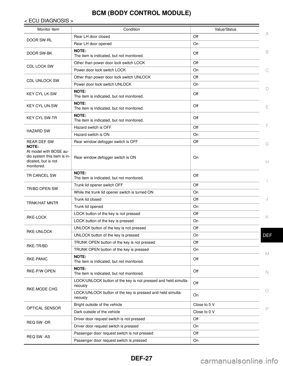
BCM (BODY CONTROL MODULE)
DEF-27
< ECU DIAGNOSIS >
C
D
E
F
G
H
I
J
K
MA
B
DEF
N
O
P
DOOR SW-RLRear LH door closed Off
Rear LH door opened On
DOOR SW-BKNOTE:
The item is indicated, but not monitored. Off
CDL LOCK SWOther than power door lock switch LOCK Off
Power door lock switch LOCK On
CDL UNLOCK SWOther than power door lock switch UNLOCK Off
Power door lock switch UNLOCK On
KEY CYL LK-SWNOTE:
The item is indicated, but not monitored. Off
KEY CYL UN-SWNOTE:
The item is indicated, but not monitored. Off
KEY CYL SW-TRNOTE:
The item is indicated, but not monitored. Off
HAZARD SWHazard switch is OFF Off
Hazard switch is ON On
REAR DEF SW
NOTE:
At model with BOSE au-
dio system this item is in-
dicated, but is not
monitored.Rear window defogger switch is OFF Off
Rear window defogger switch is ON On
TR CANCEL SWNOTE:
The item is indicated, but not monitored. Off
TR/BD OPEN SWTrunk lid opener switch OFF Off
While the trunk lid opener switch is turned ON On
TRNK/HAT MNTRTrunk lid closed Off
Trunk lid opened On
RKE-LOCKLOCK button of the key is not pressed Off
LOCK button of the key is pressed On
RKE-UNLOCKUNLOCK button of the key is not pressed Off
UNLOCK button of the key is pressed On
RKE-TR/BDTRUNK OPEN button of the key is not pressed Off
TRUNK OPEN button of the key is pressed On
RKE-PANICNOTE:
The item is indicated, but not monitored. Off
RKE-P/W OPENNOTE:
The item is indicated, but not monitored. Off
RKE-MODE CHGLOCK/UNLOCK button of the key is not pressed and held simulta-
neouslyOff
LOCK/UNLOCK button of the key is pressed and held simulta-
neouslyOn
OPTICAL SENSORBright outside of the vehicle Close to 5 V
Dark outside of the vehicle Close to 0 V
REQ SW -DRDriver door request switch is not pressed Off
Driver door request switch is pressed On
REQ SW -ASPassenger door request switch is not pressed Off
Passenger door request switch is pressed On Monitor Item Condition Value/Status
Page 1195 of 5121
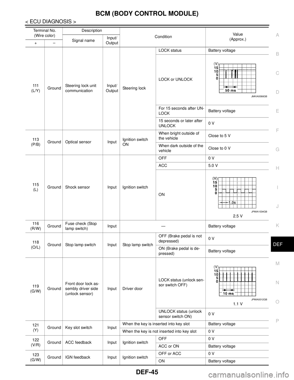
BCM (BODY CONTROL MODULE)
DEF-45
< ECU DIAGNOSIS >
C
D
E
F
G
H
I
J
K
MA
B
DEF
N
O
P
111
(L/Y)GroundSteering lock unit
communicationInput/
OutputSteering lockLOCK status Battery voltage
LOCK or UNLOCK
For 15 seconds after UN-
LOCKBattery voltage
15 seconds or later after
UNLOCK0 V
11 3
(P/B)Ground Optical sensor InputIgnition switch
ONWhen bright outside of
the vehicleClose to 5 V
When dark outside of the
vehicleClose to 0 V
11 5
(L)Ground Shock sensor Input Ignition switchOFF 0 V
ACC 5.0 V
ON
2.5 V
11 6
(R/W)GroundFuse check (Stop
lamp switch)Input — Battery voltage
11 8
(O/L)Ground Stop lamp switch Input Stop lamp switchOFF (Brake pedal is not
depressed)0 V
ON (Brake pedal is de-
pressed)Battery voltage
11 9
(G/W)GroundFront door lock as-
sembly driver side
(unlock sensor)Input Driver doorLOCK status (unlock sen-
sor switch OFF)
1.1 V
UNLOCK status (unlock
sensor switch ON)0 V
121
(Y)Ground Key slot switch InputWhen the key is inserted into key slot Battery voltage
When the key is not inserted into key slot 0 V
122
(V/R)Ground ACC feedback Input Ignition switchOFF 0 V
ACC or ON Battery voltage
123
(G/W)Ground IGN feedback Input Ignition switchOFF or ACC 0 V
ON Battery voltage Te r m i n a l N o .
(Wire color)Description
ConditionVa l u e
(Approx.)
Signal nameInput/
Output +–
JMKIA0066GB
JPMIA1034GB
JPMIA0012GB
Page 1218 of 5121

DLK-2
COMMON ITEM : CONSULT-III Function (BCM -
COMMON ITEM) ....................................................
41
DOOR LOCK .............................................................42
DOOR LOCK : CONSULT-III Function (BCM -
DOOR LOCK) .........................................................
42
INTELLIGENT KEY ...................................................43
INTELLIGENT KEY : CONSULT-III Function
(BCM - INTELLIGENT KEY) ...................................
43
TRUNK ......................................................................46
TRUNK : CONSULT-III Function (BCM - TRUNK) ...46
COMPONENT DIAGNOSIS ........................48
U1000 CAN COMM CIRCUIT ............................48
BCM ...........................................................................48
BCM : Description ...................................................48
BCM : DTC Logic ....................................................48
BCM : Diagnosis Procedure ...................................48
U1010 CONTROL UNIT (CAN) .........................49
BCM ...........................................................................49
BCM : DTC Logic ....................................................49
BCM : Diagnosis Procedure ...................................49
BCM : Special Repair Requirement ........................49
B2621 INSIDE KEY ANTENNA 1 ......................50
Description ..............................................................50
DTC Logic ...............................................................50
Diagnosis Procedure ..............................................50
B2622 INSIDE KEY ANTENNA 2 ......................52
Description ..............................................................52
DTC Logic ...............................................................52
Diagnosis Procedure ..............................................52
B2623 INSIDE KEY ANTENNA 3 ......................54
Description ..............................................................54
DTC Logic ...............................................................54
Diagnosis Procedure ..............................................54
POWER SUPPLY AND GROUND CIRCUIT .....56
BCM (BODY CONTROL MODULE) .........................56
BCM (BODY CONTROL MODULE) : Diagnosis
Procedure ...............................................................
56
DOOR SWITCH .................................................57
Description ..............................................................57
Component Function Check .................................57
Diagnosis Procedure ..............................................57
Component Inspection ............................................59
DOOR LOCK AND UNLOCK SWITCH .............60
Description ..............................................................60
Component Function Check .................................60
Diagnosis Procedure ..............................................60
DOOR LOCK ACTUATOR ................................61
DRIVER SIDE ............................................................61
DRIVER SIDE : Description ....................................61
DRIVER SIDE : Component Function Check ........61
DRIVER SIDE : Diagnosis Procedure .....................61
PASSENGER SIDE ...................................................61
PASSENGER SIDE : Description ...........................62
PASSENGER SIDE :
Component Function Check ..................................
62
PASSENGER SIDE : Diagnosis Procedure ............62
REAR LH ...................................................................62
REAR LH : Description ...........................................62
REAR LH : Component Function Check ...............63
REAR LH : Diagnosis Procedure ............................63
REAR RH ...................................................................63
REAR RH : Description ...........................................63
REAR RH : Component Function Check ...............63
REAR RH : Diagnosis Procedure ...........................64
TRUNK LID OPENER ACTUATOR ..................65
Description ..............................................................65
Component Function Check ..................................65
Diagnosis Procedure ...............................................65
REMOTE KEYLESS ENTRY RECEIVER .........67
Description ..............................................................67
Component Function Check ..................................67
Diagnosis Procedure ...............................................67
TRUNK LID OPENER SWITCH ........................70
Description ..............................................................70
Component Function Check ..................................70
Diagnosis Procedure ...............................................70
Component Inspection ............................................71
DOOR REQUEST SWITCH ...............................72
Description ..............................................................72
Component Function Check ..................................72
Diagnosis Procedure ...............................................72
Component Inspection ............................................73
TRUNK LID OPENER REQUEST SWITCH ......74
Description ..............................................................74
Component Function Check ..................................74
Diagnosis Procedure ...............................................74
Component Inspection ............................................75
TRUNK ROOM LAMP SWITCH ........................76
Description ..............................................................76
Component Function Check ..................................76
Diagnosis Procedure ...............................................76
Component Inspection ............................................77
UNLOCK SENSOR ............................................78
Description ..............................................................78
Component Function Check ..................................78
Diagnosis Procedure ...............................................78
Component Inspection ............................................79
OUTSIDE KEY ANTENNA ................................80