2008 NISSAN TEANA check oil
[x] Cancel search: check oilPage 1091 of 5121
![NISSAN TEANA 2008 Service Manual BRC-150
< PRECAUTION >[VDC/TCS/ABS]
PRECAUTIONS
Precaution for Brake Control
INFOID:0000000003767032
When starting engine or when starting vehicle just after starting engine, brake pedal may vibrate NISSAN TEANA 2008 Service Manual BRC-150
< PRECAUTION >[VDC/TCS/ABS]
PRECAUTIONS
Precaution for Brake Control
INFOID:0000000003767032
When starting engine or when starting vehicle just after starting engine, brake pedal may vibrate](/manual-img/5/57391/w960_57391-1090.png)
BRC-150
< PRECAUTION >[VDC/TCS/ABS]
PRECAUTIONS
Precaution for Brake Control
INFOID:0000000003767032
When starting engine or when starting vehicle just after starting engine, brake pedal may vibrate or motor
operating noise may be heard from engine compartment. This is normal condition.
When an error is indicated by ABS or another warning lamp, collect all necessary information from customer
(what symptoms are present under what conditions) and check for estimate causes before starting diagnos-
tic servicing. Besides electrical system inspection, check brake booster operation, brake fluid level, and oil
leaks.
If tire size and type are used in an improper combination, or brake pads are not Genuine NISSAN parts,
stopping distance or steering stability may deteriorate.
ABS might be out of order or malfunctions by putting a radio (wiring inclusive), an antenna and a lead-in wire
near the control unit.
If aftermarket parts (car stereo, CD player, etc.) have been installed, check for incidents such as harness
pinches, open circuits, and improper wiring.
VDC system may not operate normally or a VDC OFF indicator lamp or SLIP indicator lamp may light.
- When replacing the following parts with parts other than genuine parts or making modifications: Suspension
related parts (shock absorber, spring, bushing, etc.), tires, wheels (other than specified sizes), brake-related
parts (pad, rotor, caliper, etc.), engine-related parts (muffler, ECM, etc.) and body reinforcement-related parts
(roll bar, tower bar, etc.).
- When driving with worn or deteriorated suspension, tires and brake-related parts.
Precautions for Harness RepairINFOID:0000000003843440
COMMUNICATION LINE
Solder the repaired area and wrap tape around the soldered area.
NOTE:
A fray of twisted lines must be within 110 mm (4.33 in).
Bypass connection is never allowed at the repaired area.
NOTE:
Bypass connection may cause communication error as spliced
wires that are separate from the main line or twisted lines lose
noise immunity.
Replace the applicable harness as an assembly if error is detected
on the shield lines of communication line.
SKIB8766E
SKIB8767E
Page 1102 of 5121
CHG-4
< BASIC INSPECTION >
DIAGNOSIS AND REPAIR WORKFLOW
YES >> GO TO 10.
NO >> Repair as needed.
10.DISASSEMBLE AND CHECK ALTERNATOR
Check the following conditions. Refer to CHG-24, "
Inspection".
Rotor coil
Rotor slip ring
Brush
Stator coil
Are these normal?
YES >> Replace IC regulator and/or diode assembly.
NO >> Repair as needed.
11 .INSPECTION WITH CHARGE WARNING LAMP (IGNITION SWITCH IS ON)
1. Disconnect alternator connector and ground “L” harness side.
2. Turn the ignition switch ON.
Does the charge warning lamp illuminate?
YES >> GO TO 12.
NO >> GO TO 13.
12.DISASSEMBLE AND CHECK ALTERNATOR
Check the following conditions. Refer to CHG-24, "
Inspection".
Rotor coil
Rotor slip ring
Brush
Are these normal?
YES >> Replace IC regulator.
NO >> Repair as needed.
13.CHECK “L” TERMINAL CIRCUIT (OPEN)
Check “L” terminal circuit (open). Refer to CHG-10, "
Diagnosis Procedure".
>> Repair as needed.
Page 1129 of 5121
CO-6
< PRECAUTION >
PRECAUTIONS
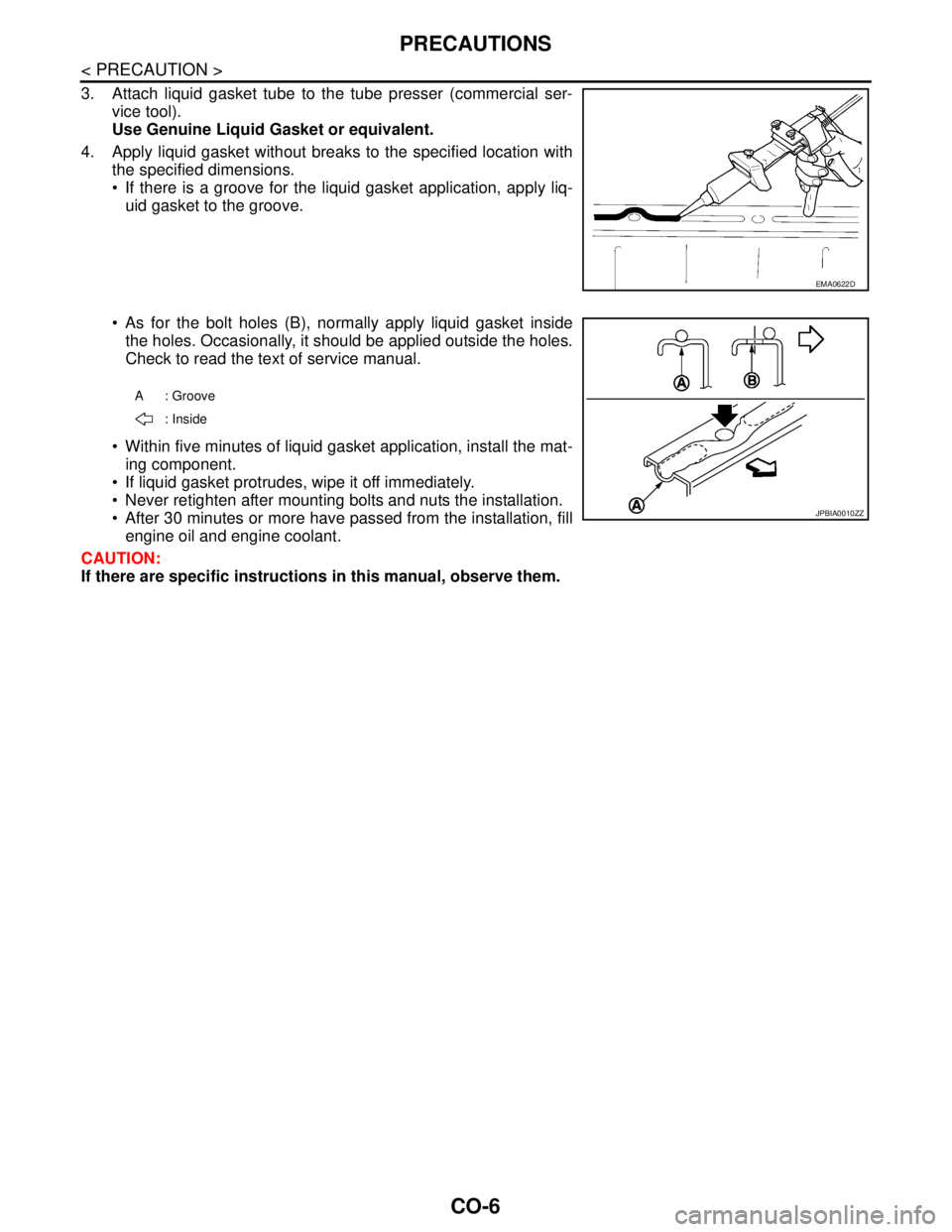
3. Attach liquid gasket tube to the tube presser (commercial ser-
vice tool).
Use Genuine Liquid Gasket or equivalent.
4. Apply liquid gasket without breaks to the specified location with
the specified dimensions.
If there is a groove for the liquid gasket application, apply liq-
uid gasket to the groove.
As for the bolt holes (B), normally apply liquid gasket inside
the holes. Occasionally, it should be applied outside the holes.
Check to read the text of service manual.
Within five minutes of liquid gasket application, install the mat-
ing component.
If liquid gasket protrudes, wipe it off immediately.
Never retighten after mounting bolts and nuts the installation.
After 30 minutes or more have passed from the installation, fill
engine oil and engine coolant.
CAUTION:
If there are specific instructions in this manual, observe them.
EMA0622D
A: Groove
: Inside
JPBIA0010ZZ
Page 1135 of 5121
CO-12
< ON-VEHICLE MAINTENANCE >
RADIATOR
RADIATOR
RADIATOR CAP
RADIATOR CAP : InspectionINFOID:0000000003793170
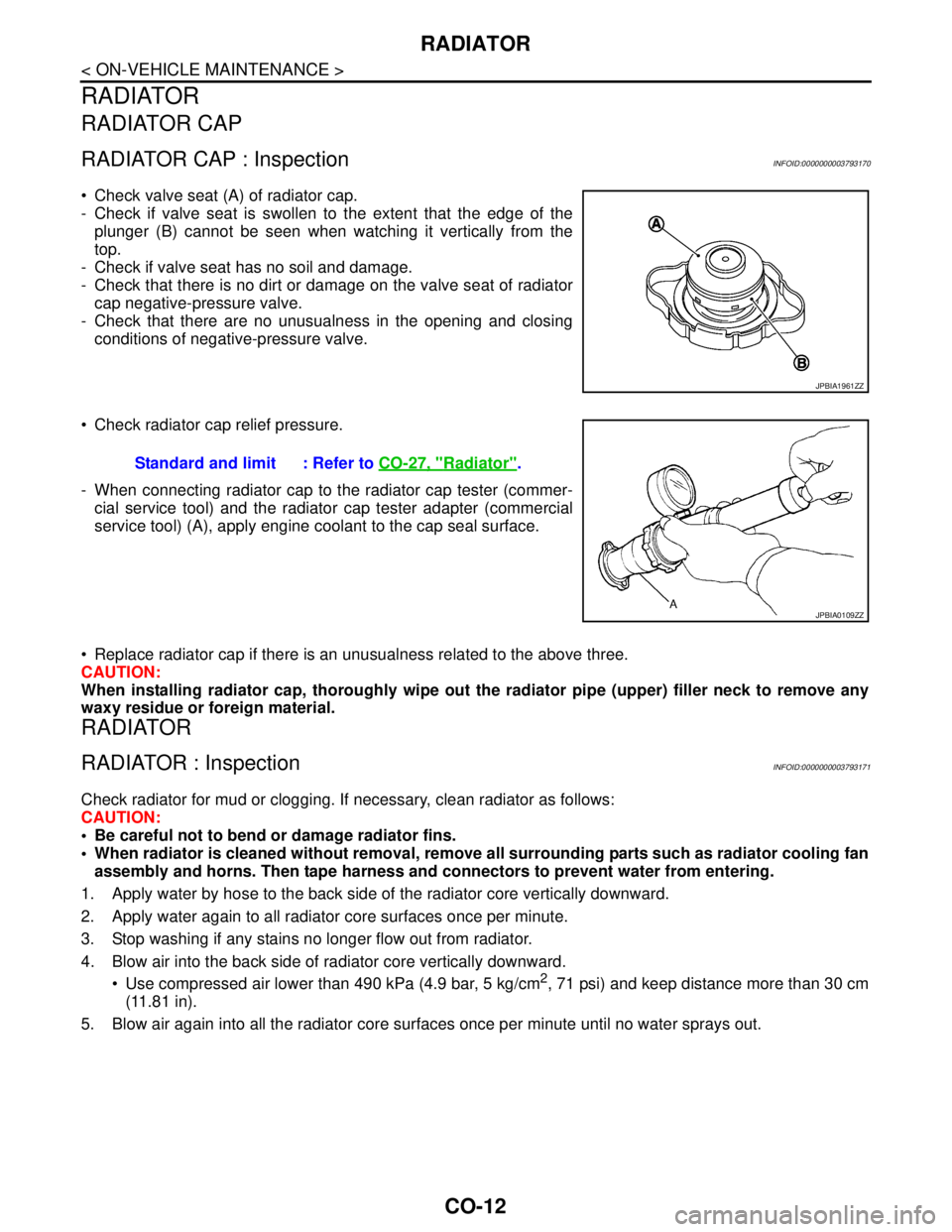
Check valve seat (A) of radiator cap.
- Check if valve seat is swollen to the extent that the edge of the
plunger (B) cannot be seen when watching it vertically from the
top.
- Check if valve seat has no soil and damage.
- Check that there is no dirt or damage on the valve seat of radiator
cap negative-pressure valve.
- Check that there are no unusualness in the opening and closing
conditions of negative-pressure valve.
Check radiator cap relief pressure.
- When connecting radiator cap to the radiator cap tester (commer-
cial service tool) and the radiator cap tester adapter (commercial
service tool) (A), apply engine coolant to the cap seal surface.
Replace radiator cap if there is an unusualness related to the above three.
CAUTION:
When installing radiator cap, thoroughly wipe out the radiator pipe (upper) filler neck to remove any
waxy residue or foreign material.
RADIATOR
RADIATOR : InspectionINFOID:0000000003793171
Check radiator for mud or clogging. If necessary, clean radiator as follows:
CAUTION:
Be careful not to bend or damage radiator fins.
When radiator is cleaned without removal, remove all surrounding parts such as radiator cooling fan
assembly and horns. Then tape harness and connectors to prevent water from entering.
1. Apply water by hose to the back side of the radiator core vertically downward.
2. Apply water again to all radiator core surfaces once per minute.
3. Stop washing if any stains no longer flow out from radiator.
4. Blow air into the back side of radiator core vertically downward.
Use compressed air lower than 490 kPa (4.9 bar, 5 kg/cm
2, 71 psi) and keep distance more than 30 cm
(11.81 in).
5. Blow air again into all the radiator core surfaces once per minute until no water sprays out.
JPBIA1961ZZ
Standard and limit : Refer to CO-27, "Radiator".
JPBIA0109ZZ
Page 1141 of 5121
CO-18
< ON-VEHICLE REPAIR >
WATER PUMP
WATER PUMP
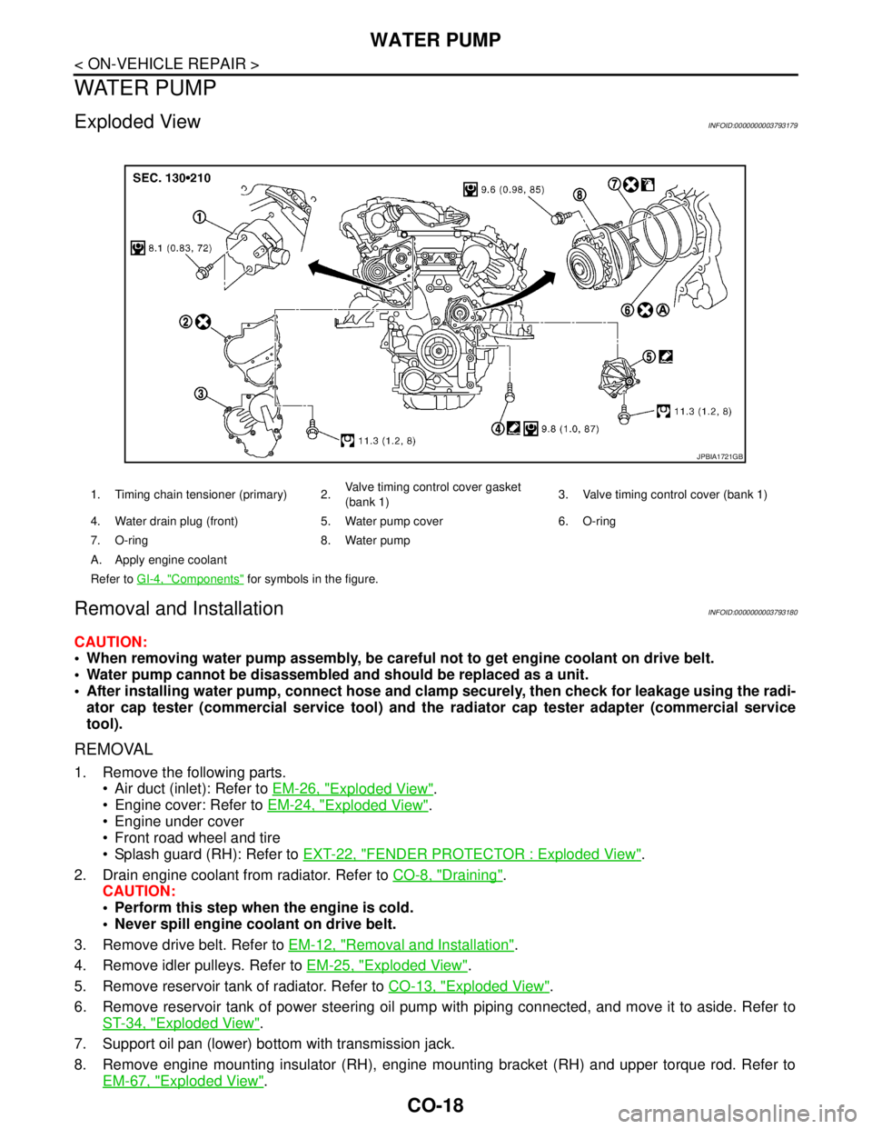
Exploded ViewINFOID:0000000003793179
Removal and InstallationINFOID:0000000003793180
CAUTION:
When removing water pump assembly, be careful not to get engine coolant on drive belt.
Water pump cannot be disassembled and should be replaced as a unit.
After installing water pump, connect hose and clamp securely, then check for leakage using the radi-
ator cap tester (commercial service tool) and the radiator cap tester adapter (commercial service
tool).
REMOVAL
1. Remove the following parts.
Air duct (inlet): Refer to EM-26, "
Exploded View".
Engine cover: Refer to EM-24, "
Exploded View".
Engine under cover
Front road wheel and tire
Splash guard (RH): Refer to EXT-22, "
FENDER PROTECTOR : Exploded View".
2. Drain engine coolant from radiator. Refer to CO-8, "
Draining".
CAUTION:
Perform this step when the engine is cold.
Never spill engine coolant on drive belt.
3. Remove drive belt. Refer to EM-12, "
Removal and Installation".
4. Remove idler pulleys. Refer to EM-25, "
Exploded View".
5. Remove reservoir tank of radiator. Refer to CO-13, "
Exploded View".
6. Remove reservoir tank of power steering oil pump with piping connected, and move it to aside. Refer to
ST-34, "
Exploded View".
7. Support oil pan (lower) bottom with transmission jack.
8. Remove engine mounting insulator (RH), engine mounting bracket (RH) and upper torque rod. Refer to
EM-67, "
Exploded View".
1. Timing chain tensioner (primary) 2.Valve timing control cover gasket
(bank 1)3. Valve timing control cover (bank 1)
4. Water drain plug (front) 5. Water pump cover 6. O-ring
7. O-ring 8. Water pump
A. Apply engine coolant
Refer to GI-4, "
Components" for symbols in the figure.
JPBIA1721GB
Page 1143 of 5121
![NISSAN TEANA 2008 Service Manual CO-20
< ON-VEHICLE REPAIR >
WATER PUMP
b. Screw M8 bolts [pitch: 1.25 mm (0.0492 in) length: approxi-
mately 50 mm (1.97 in)] into water pumps upper and lower
mounting bolt holes until they reach timi NISSAN TEANA 2008 Service Manual CO-20
< ON-VEHICLE REPAIR >
WATER PUMP
b. Screw M8 bolts [pitch: 1.25 mm (0.0492 in) length: approxi-
mately 50 mm (1.97 in)] into water pumps upper and lower
mounting bolt holes until they reach timi](/manual-img/5/57391/w960_57391-1142.png)
CO-20
< ON-VEHICLE REPAIR >
WATER PUMP
b. Screw M8 bolts [pitch: 1.25 mm (0.0492 in) length: approxi-
mately 50 mm (1.97 in)] into water pumps upper and lower
mounting bolt holes until they reach timing chain case. Then,
alternately tighten each bolt for a half turn, and pull out water
pump.
CAUTION:
Pull straight out while preventing vane from contacting
socket in installation area.
Remove water pump without causing sprocket to contact
timing chain.
c. Remove M8 bolts and O-rings from water pump.
CAUTION:
Never disassemble water pump.
INSTALLATION
1. Install new O-rings to water pump.
Apply engine oil and engine coolant to O-rings as shown in the
figure.
Locate O-ring with white paint mark to engine front side.
2. Install water pump.
CAUTION:
Never allow cylinder block to nip O-rings when installing
water pump.
Check that timing chain and water pump sprocket are
engaged.
Insert water pump by tightening mounting bolts alternately and
evenly.
3. Install timing chain tensioner (primary) as follows:
a. Turn crankshaft pulley clockwise so that timing chain on the tim-
ing chain tensioner (primary) side is loose.
JLC357B
PBIC1397E
SLC031B
PBIC4820E
Page 1466 of 5121
EC-5
C
D
E
F
G
H
I
J
K
L
M
ECA
N
O
P
P2122, P2123 APP SENSOR ...........................304
Description ............................................................304
DTC Logic .............................................................304
Diagnosis Procedure .............................................304
Component Inspection ..........................................306
Special Repair Requirement .................................306
P2127, P2128 APP SENSOR ...........................307
Description ............................................................307
DTC Logic .............................................................307
Diagnosis Procedure .............................................307
Component Inspection ..........................................309
Special Repair Requirement .................................310
P2135 TP SENSOR ..........................................311
Description ............................................................311
DTC Logic .............................................................311
Diagnosis Procedure .............................................311
Component Inspection ..........................................313
Special Repair Requirement .................................313
P2138 APP SENSOR .......................................314
Description ............................................................314
DTC Logic .............................................................314
Diagnosis Procedure .............................................314
Component Inspection ..........................................316
Special Repair Requirement .................................317
P2A00, P2A03 A/F SENSOR 1 ........................318
Description ............................................................318
DTC Logic .............................................................318
Diagnosis Procedure .............................................319
ASCD BRAKE SWITCH ...................................321
Description ............................................................321
Component Function Check ..................................321
Diagnosis Procedure .............................................321
Component Inspection (ASCD Brake Switch) .......322
ASCD INDICATOR ...........................................323
Description ............................................................323
Component Function Check ..................................323
Diagnosis Procedure .............................................323
COOLING FAN .................................................324
Description ............................................................324
Component Function Check ..................................324
Diagnosis Procedure .............................................324
Component Inspection (Cooling Fan Motor) .........327
Component Inspection (Cooling Fan Relay) .........328
ELECTRICAL LOAD SIGNAL .........................329
Description ............................................................329
Component Function Check ..................................329
Diagnosis Procedure .............................................329
ELECTRONIC CONTROLLED ENGINE
MOUNT .............................................................
331
Description ............................................................331
Component Function Check ..................................331
Diagnosis Procedure .............................................331
Component Inspection ...........................................332
FUEL INJECTOR ............................................334
Description .............................................................334
Component Function Check ..................................334
Diagnosis Procedure .............................................334
Component Inspection ...........................................336
FUEL PUMP ....................................................337
Description .............................................................337
Component Function Check ..................................337
Diagnosis Procedure .............................................337
Component Inspection (Fuel Pump) ......................340
Component Inspection (Condenser) ......................340
IGNITION SIGNAL ..........................................341
Description .............................................................341
Component Function Check ..................................341
Diagnosis Procedure .............................................341
Component Inspection (Ignition Coil with Power
Transistor) .............................................................
344
Component Inspection (Condenser) ......................345
MALFUNCTION INDICATOR .........................346
Description .............................................................346
Component Function Check ..................................346
Diagnosis Procedure .............................................346
POSITIVE CRANKCASE VENTILATION .......347
Description .............................................................347
Component Inspection ...........................................347
REFRIGERANT PRESSURE SENSOR ..........348
Description .............................................................348
Component Function Check ..................................348
Diagnosis Procedure .............................................348
VARIABLE INDUCTION AIR SYSTEM ..........351
Description .............................................................351
Component Function Check (VQ35DE engine) .....351
Component Function Check (VQ25DE engine) .....353
Diagnosis Procedure (VQ35DE engine) ................353
Diagnosis Procedure (VQ25DE engine) ................355
ECU DIAGNOSIS .......................................357
ECM .................................................................357
Reference Value ....................................................357
Wiring Diagram—ENGINE CONTROL SYS-
TEM— ...................................................................
371
Fail safe .................................................................386
DTC Inspection Priority Chart .............................388
DTC Index .............................................................389
How to Set SRT Code ........................................392
Test Value and Test Limit ...................................394
SYMPTOM DIAGNOSIS ............................400
ENGINE CONTROL SYSTEM SYMPTOMS ...400
Symptom Table .....................................................400
NORMAL OPERATING CONDITION .............404
Page 1581 of 5121
![NISSAN TEANA 2008 Service Manual EC-120
< FUNCTION DIAGNOSIS >[VQ25DE, VQ35DE]
ON BOARD DIAGNOSTIC (OBD) SYSTEM
*: This item is not used on this vehicle.
NOTE:
Any monitored item that does not match the vehicle being diagnosed is del NISSAN TEANA 2008 Service Manual EC-120
< FUNCTION DIAGNOSIS >[VQ25DE, VQ35DE]
ON BOARD DIAGNOSTIC (OBD) SYSTEM
*: This item is not used on this vehicle.
NOTE:
Any monitored item that does not match the vehicle being diagnosed is del](/manual-img/5/57391/w960_57391-1580.png)
EC-120
< FUNCTION DIAGNOSIS >[VQ25DE, VQ35DE]
ON BOARD DIAGNOSTIC (OBD) SYSTEM
*: This item is not used on this vehicle.
NOTE:
Any monitored item that does not match the vehicle being diagnosed is deleted from the display automatically.
ACTIVE TEST MODE
Test Item
SET LAMP ON/OFF Indicates [ON/OFF] condition of SET lamp deter-
mined by the ECM according to the input signals.
BAT CUR SEN mV The signal voltage of battery current sensor is
displayed.
ALT DUTY SIG ON/OFF The control condition of the power generation
voltage variable control (determined by ECM ac-
cording to the input signals) is indicated.
ON: Power generation voltage variable control is
active.
OFF: Power generation voltage variable control
is inactive.
A/F ADJ-B1
— Indicates the correction of factor stored in ECM.
The factor is calculated from the difference be-
tween the target air-fuel ratio stored in ECM and
the air-fuel ratio calculated from A/F sensor 1 sig-
nal. A/F ADJ-B2
ALT DUTY % Indicates the duty ratio of the power generation
command value. The ratio is calculated by ECM
based on the battery current sensor signal. Monitored item Unit Description Remarks
TEST ITEM CONDITION JUDGMENT CHECK ITEM (REMEDY)
FUEL INJEC-
TION Engine: Return to the original
non-standard condition
Change the amount of fuel injec-
tion using CONSULT-III.If malfunctioning symptom disap-
pears, see CHECK ITEM. Harness and connectors
Fuel injector
Air fuel ratio (A/F) sensor 1
IGNITION TIM-
ING Engine: Return to the original
non-standard condition
Timing light: Set
Retard the ignition timing using
CONSULT-III.If malfunctioning symptom disap-
pears, see CHECK ITEM. Perform Idle Air Volume Learning.
POWER BAL-
ANCE Engine: After warming up, idle the
engine.
A/C switch OFF
Selector lever: P or N
Cut off each injector signal one at
a time using CONSULT-III.Engine runs rough or dies. Harness and connectors
Compression
Fuel injector
Power transistor
Spark plug
Ignition coil
COOLING FAN*
1
Ignition switch: ON
Turn the cooling fan “HI”, “MID”,
“LOW” and “OFF” using CON-
SULT-III.Cooling fan moves and stops. Harness and connectors
Cooling fan motor
IPDM E/R
ENG COOLANT
TEMP Engine: Return to the original
non-standard condition
Change the engine coolant tem-
perature using CONSULT-III.If malfunctioning symptom disap-
pears, see CHECK ITEM. Harness and connectors
Engine coolant temperature sen-
sor
Fuel injector
FUEL PUMP RE-
LAY Ignition switch: ON (Engine
stopped)
Turn the fuel pump relay “ON”
and “OFF” using CONSULT-III
and listen to operating sound.Fuel pump relay makes the operat-
ing sound. Harness and connectors
Fuel pump relay