2008 NISSAN TEANA automatic transmission
[x] Cancel search: automatic transmissionPage 830 of 5121

BCS
POWER CONSUMPTION CONTROL SYSTEM
BCS-13
< FUNCTION DIAGNOSIS >
C
D
E
F
G
H
I
J
K
L B A
O
P N
POWER CONSUMPTION CONTROL SYSTEM
System DiagramINFOID:0000000003809591
System DescriptionINFOID:0000000003809592
OUTLINE
BCM incorporates a power saving control function that reduces the power consumption according to the
vehicle status.
BCM switches the status (control mode) by itself with the power saving control function. It performs the sleep
request to each unit (IPDM E/R, combination meter, driver seat control unit and automatic back door control
unit) that operates with the ignition switch OFF.
Normal mode (wake-up)- CAN communication is normally performed with other units
- Each control with BCM is operating properly
CAN communication sleep mode (CAN sleep)- CAN transmission is stopped
- Control with BCM only is operating
Low power consumption mode (BCM sleep)- Low power consumption control is active
- CAN transmission is stopped
LOW POWER CONSUMPTION CONTROL WITH BCM
BCM reduces the power consumption with the following operation in the low power consumption mode.
The reading interval of the each switches changes from 10 ms interval to 60 ms interval.
Sleep mode activation
BCM receives the sleep-ready signal (ready) from IPDM E/R and combination meter via CAN communica-
tion.
BCM transmits the sleep wake up signal (sleep) to each unit when all of the CAN sleep conditions are ful-
filled.
Each unit stops the transmission of CAN communication with the sleep wake up signal. BCM is in CAN com-
munication sleep mode.
BCM is in the low power consumption mode and perform the low power consumption control when all of the
BCM sleep conditions are fulfilled with CAN sleep condition.
JPMIA1046GB
Page 2496 of 5121

HOW TO USE THIS MANUAL
GI-3
< HOW TO USE THIS MANUAL >
C
D
E
F
G
H
I
J
K
L
MB
GI
N
O
PHOW TO USE THIS MANUAL
HOW TO USE THIS MANUAL
DescriptionINFOID:0000000003852757
This volume explains “Removal, Disassembly, Installation, Inspection and Adjustment” and “Trouble Diag-
noses”.
Te r m sINFOID:0000000003852758
The captions WARNING and CAUTION warn you of steps that must be followed to prevent personal injury
and/or damage to some part of the vehicle.
WARNING indicates the possibility of personal injury if instructions are not followed.
CAUTION indicates the possibility of component damage if instructions are not followed.
BOLD TYPED STATEMENTS except WARNING and CAUTION give you helpful information.
Standard value: Tolerance at inspection and adjustment.
Limit value: The maximum or minimum limit value that should not be exceeded at inspection and adjust-
ment.
UnitsINFOID:0000000003852759
The UNITS given in this manual are primarily expressed as the SI UNIT (International System of Unit), and
alternatively expressed in the metric system and in the yard/pound system.
Also with regard to tightening torque of bolts and nuts, there are descriptions both about range and about the
standard tightening torque.
“Example”
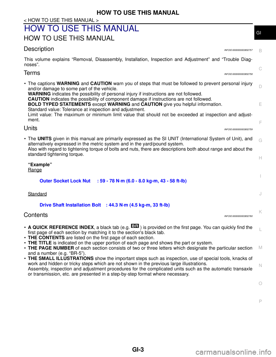
Range
Standard
ContentsINFOID:0000000003852760
A QUICK REFERENCE INDEX, a black tab (e.g. ) is provided on the first page. You can quickly find the
first page of each section by matching it to the section's black tab.
THE CONTENTS are listed on the first page of each section.
THE TITLE is indicated on the upper portion of each page and shows the part or system.
THE PAGE NUMBER of each section consists of two or three letters which designate the particular section
and a number (e.g. “BR-5”).
THE SMALL ILLUSTRATIONS show the important steps such as inspection, use of special tools, knacks of
work and hidden or tricky steps which are not shown in the previous large illustrations.
Assembly, inspection and adjustment procedures for the complicated units such as the automatic transaxle
or transmission, etc. are presented in a step-by-step format where necessary. Outer Socket Lock Nut : 59 - 78 N·m (6.0 - 8.0 kg-m, 43 - 58 ft-lb)
Drive Shaft Installation Bolt: 44.3 N·m (4.5 kg-m, 33 ft-lb)
Page 2506 of 5121

ABBREVIATIONS
GI-13
< HOW TO USE THIS MANUAL >
C
D
E
F
G
H
I
J
K
L
MB
GI
N
O
PABBREVIATIONS
Abbreviation ListINFOID:0000000003852769
The following ABBREVIATIONS are used:
ABBREVIATION DESCRIPTION
A/C Air Conditioner
A/T Automatic Transaxle/Transmission
ATF Automatic Transmission Fluid
D
1Drive range 1st gear
D
2Drive range 2nd gear
D
3Drive range 3rd gear
D
4Drive range 4th gear
FR, RR Front, Rear
LH, RH Left-Hand, Right-Hand
M/T Manual Transaxle/Transmission
OD Overdrive
P/S Power Steering
SAE Society of Automotive Engineers, Inc.
SDS Service Data and Specifications
SST Special Service Tools
2WD 2-Wheel Drive
2
22nd range 2nd gear
2
12nd range 1st gear
1
21st range 2nd gear
1
11st range 1st gear
Page 2515 of 5121

GI-22
< FEATURES OF NEW MODEL >
IDENTIFICATION INFORMATION
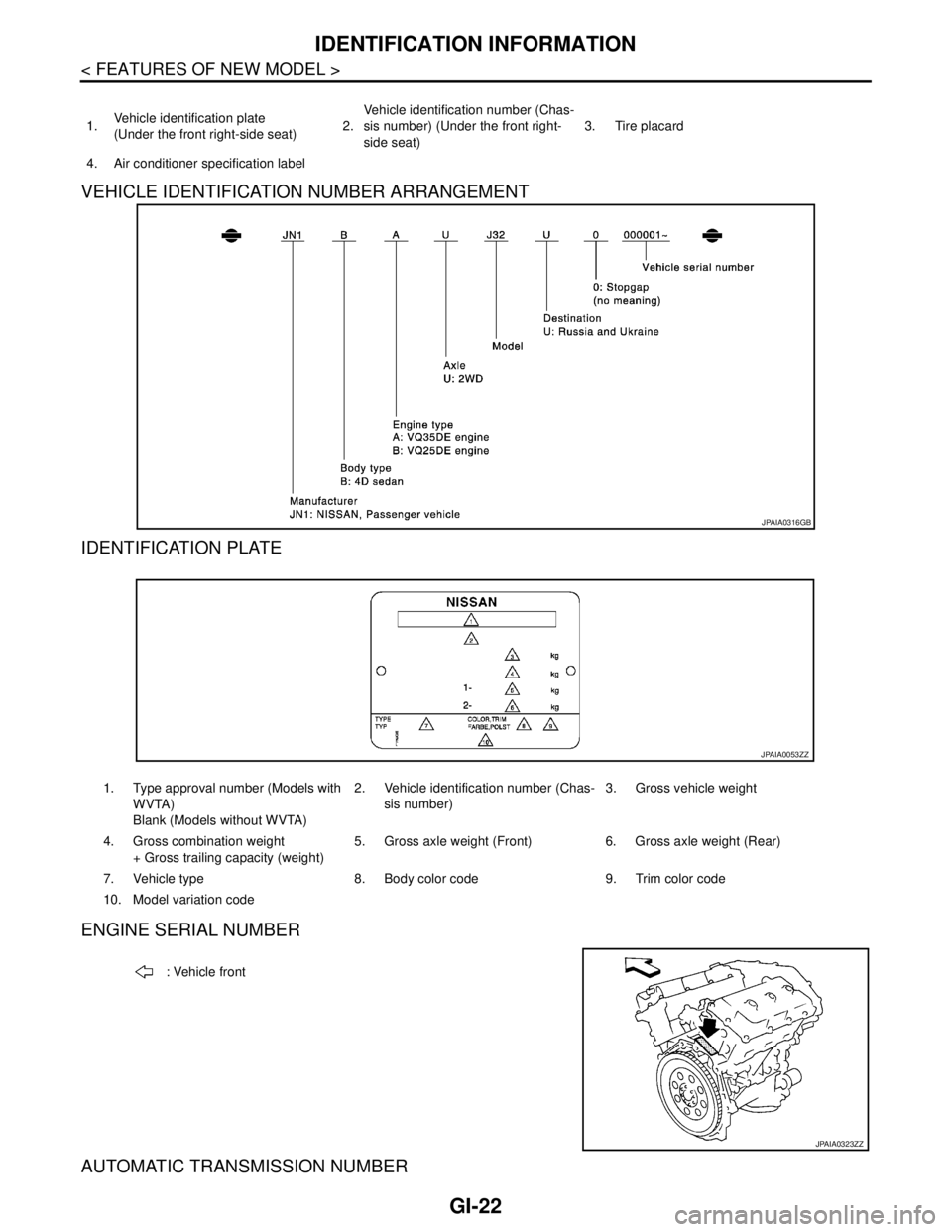
VEHICLE IDENTIFICATION NUMBER ARRANGEMENT
IDENTIFICATION PLATE
ENGINE SERIAL NUMBER
AUTOMATIC TRANSMISSION NUMBER
1.Vehicle identification plate
(Under the front right-side seat)2.Vehicle identification number (Chas-
sis number) (Under the front right-
side seat)3. Tire placard
4. Air conditioner specification label
JPAIA0316GB
1. Type approval number (Models with
WVTA)
Blank (Models without WVTA)2. Vehicle identification number (Chas-
sis number)3. Gross vehicle weight
4. Gross combination weight
+ Gross trailing capacity (weight)5. Gross axle weight (Front) 6. Gross axle weight (Rear)
7. Vehicle type 8. Body color code 9. Trim color code
10. Model variation code
JPAIA0053ZZ
: Vehicle front
JPAIA0323ZZ
Page 2519 of 5121

GI-26
< PRECAUTION >
PRECAUTIONS
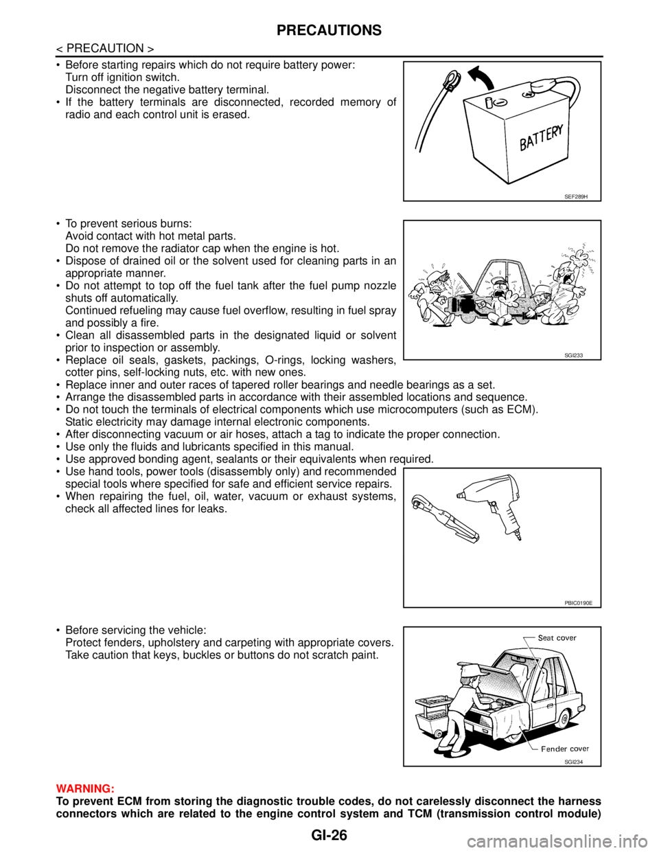
Before starting repairs which do not require battery power:
Turn off ignition switch.
Disconnect the negative battery terminal.
If the battery terminals are disconnected, recorded memory of
radio and each control unit is erased.
To prevent serious burns:
Avoid contact with hot metal parts.
Do not remove the radiator cap when the engine is hot.
Dispose of drained oil or the solvent used for cleaning parts in an
appropriate manner.
Do not attempt to top off the fuel tank after the fuel pump nozzle
shuts off automatically.
Continued refueling may cause fuel overflow, resulting in fuel spray
and possibly a fire.
Clean all disassembled parts in the designated liquid or solvent
prior to inspection or assembly.
Replace oil seals, gaskets, packings, O-rings, locking washers,
cotter pins, self-locking nuts, etc. with new ones.
Replace inner and outer races of tapered roller bearings and needle bearings as a set.
Arrange the disassembled parts in accordance with their assembled locations and sequence.
Do not touch the terminals of electrical components which use microcomputers (such as ECM).
Static electricity may damage internal electronic components.
After disconnecting vacuum or air hoses, attach a tag to indicate the proper connection.
Use only the fluids and lubricants specified in this manual.
Use approved bonding agent, sealants or their equivalents when required.
Use hand tools, power tools (disassembly only) and recommended
special tools where specified for safe and efficient service repairs.
When repairing the fuel, oil, water, vacuum or exhaust systems,
check all affected lines for leaks.
Before servicing the vehicle:
Protect fenders, upholstery and carpeting with appropriate covers.
Take caution that keys, buckles or buttons do not scratch paint.
WARNING:
To prevent ECM from storing the diagnostic trouble codes, do not carelessly disconnect the harness
connectors which are related to the engine control system and TCM (transmission control module)
SEF289H
SGI233
PBIC0190E
SGI234
Page 2526 of 5121

TOW TRUCK TOWING
GI-33
< PRECAUTION >
C
D
E
F
G
H
I
J
K
L
MB
GI
N
O
P
Do not use the vehicle tie downs to free a vehicle stuck in sand, snow, mud, etc. Never tow the vehi-
cle using the vehicle tie downs or recovery hooks.
Always pull the cable straight out from the front of the vehicle. Never pull on the hook at an angle.
Pulling devices should be routed so they do not touch any part of the suspension, steering, brake or
cooling systems.
Pulling devices such as ropes or canvas straps are not recommended for use in vehicle towing or
recovery.
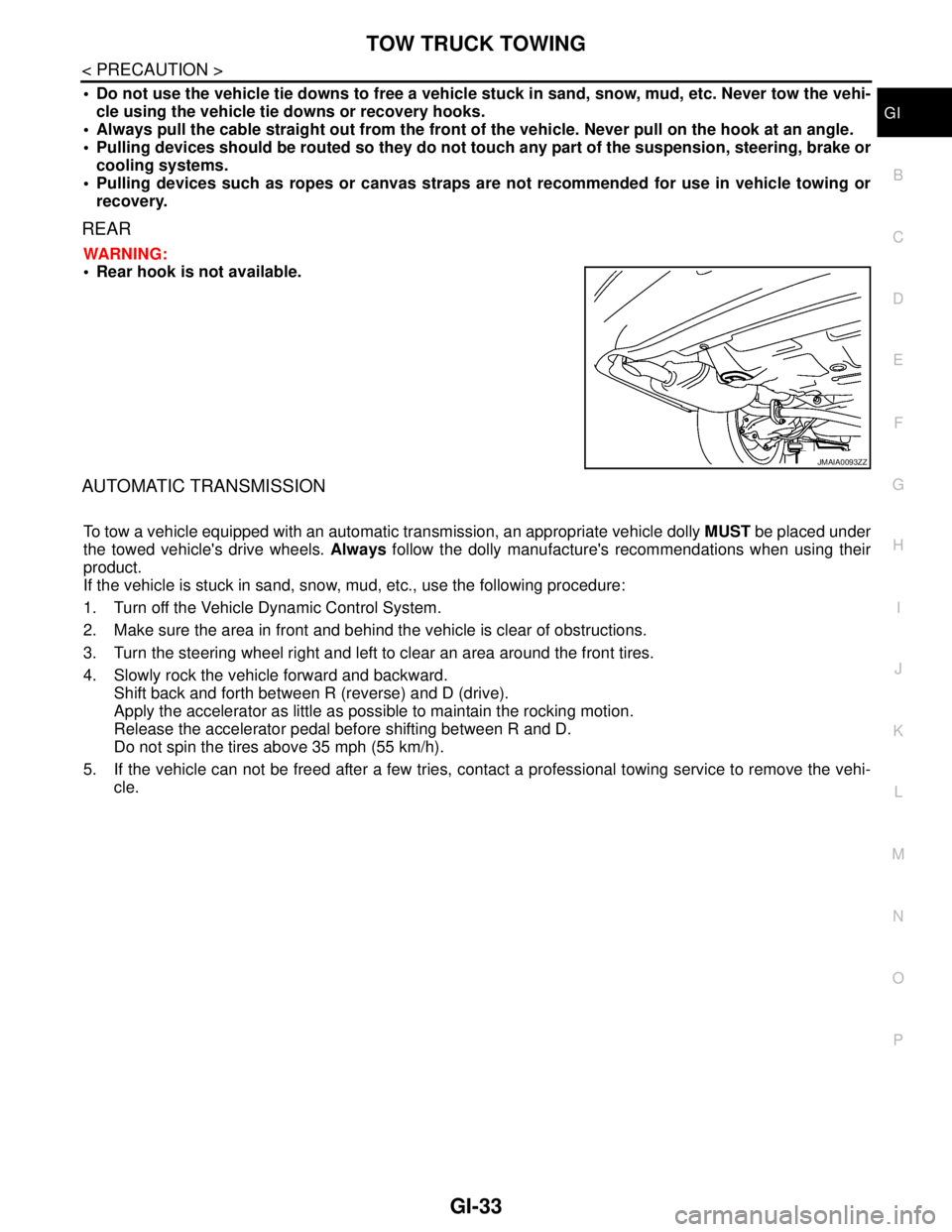
REAR
WARNING:
Rear hook is not available.
AUTOMATIC TRANSMISSION
To tow a vehicle equipped with an automatic transmission, an appropriate vehicle dolly MUST be placed under
the towed vehicle's drive wheels. Always follow the dolly manufacture's recommendations when using their
product.
If the vehicle is stuck in sand, snow, mud, etc., use the following procedure:
1. Turn off the Vehicle Dynamic Control System.
2. Make sure the area in front and behind the vehicle is clear of obstructions.
3. Turn the steering wheel right and left to clear an area around the front tires.
4. Slowly rock the vehicle forward and backward.
Shift back and forth between R (reverse) and D (drive).
Apply the accelerator as little as possible to maintain the rocking motion.
Release the accelerator pedal before shifting between R and D.
Do not spin the tires above 35 mph (55 km/h).
5. If the vehicle can not be freed after a few tries, contact a professional towing service to remove the vehi-
cle.
JMAIA0093ZZ
Page 2650 of 5121
![NISSAN TEANA 2008 Service Manual HAC-22
< FUNCTION DIAGNOSIS >[WITHOUT 7 INCH DISPLAY]
AUTOMATIC AIR CONDITIONER SYSTEM
AIR CONDITIONER LAN CONTROL SYSTEM
The LAN (Local Area Network) system consists of the A/C auto amp., the mode do NISSAN TEANA 2008 Service Manual HAC-22
< FUNCTION DIAGNOSIS >[WITHOUT 7 INCH DISPLAY]
AUTOMATIC AIR CONDITIONER SYSTEM
AIR CONDITIONER LAN CONTROL SYSTEM
The LAN (Local Area Network) system consists of the A/C auto amp., the mode do](/manual-img/5/57391/w960_57391-2649.png)
HAC-22
< FUNCTION DIAGNOSIS >[WITHOUT 7 INCH DISPLAY]
AUTOMATIC AIR CONDITIONER SYSTEM
AIR CONDITIONER LAN CONTROL SYSTEM
The LAN (Local Area Network) system consists of the A/C auto amp., the mode door motor, the air mix door
motors and the intake door motor.
A configuration of these components is as shown in the figure below.
SYSTEM CONSTRUCTION
A small network exists between the A/C auto amp., the mode door motor, the air mix door motor and the intake
door motor. The A/C auto amp. and motors are connected by data transmission lines and motor power supply
lines. The LAN network is built through the ground circuits of each door motor.
Addresses, motor opening angle signals, motor stop signals and error checking messages are all transmitted
through the data transmission lines connecting the A/C auto amp. and each door motor.
The following functions are contained in LCUs built into the mode door motor, the air mix door motors and the
intake door motor.
Address
Motor opening angle signals
Data transmission
Motor stop and drive decision
Opening angle sensor (PBR function)
Comparison
JSIIA1186GB
JSIIA1129GB
Page 2651 of 5121
![NISSAN TEANA 2008 Service Manual AUTOMATIC AIR CONDITIONER SYSTEM
HAC-23
< FUNCTION DIAGNOSIS >[WITHOUT 7 INCH DISPLAY]
C
D
E
F
G
H
J
K
L
MA
B
HAC
N
O
P
Decision (A/C auto amp. indicated value and motor opening angle comparison)
Op NISSAN TEANA 2008 Service Manual AUTOMATIC AIR CONDITIONER SYSTEM
HAC-23
< FUNCTION DIAGNOSIS >[WITHOUT 7 INCH DISPLAY]
C
D
E
F
G
H
J
K
L
MA
B
HAC
N
O
P
Decision (A/C auto amp. indicated value and motor opening angle comparison)
Op](/manual-img/5/57391/w960_57391-2650.png)
AUTOMATIC AIR CONDITIONER SYSTEM
HAC-23
< FUNCTION DIAGNOSIS >[WITHOUT 7 INCH DISPLAY]
C
D
E
F
G
H
J
K
L
MA
B
HAC
N
O
P
Decision (A/C auto amp. indicated value and motor opening angle comparison)
Operation
The A/C auto amp. receives data from each of the sensors. The A/C auto amp. sends mode door, the air mix
door and the intake door opening angle data to the mode door motor LCU, the air mix door motor LCUs and
the intake door motor LCU.
The mode door motor, the air mix door motors and the intake door motor read their respective signals accord-
ing to the address signal. Opening angle indication signals received from the A/C auto amp. and each of the
motor position sensors is compared by the LCUs in each door motor with the existing decision and opening
angles. Next, HOT/COLD, DEF/VENT, OPEN/SHUT or FRE/REC operation is selected. The new selection
data is returned to the A/C auto amp.
Transmission Data and Transmission Order
A/C auto amp. data is transmitted consecutively to each of the door motors following the form as shown in the
figure below.
START: Initial compulsory signal is sent to each of the door motors.
ADDRESS: Data sent from the A/C auto amp. is selected according to data-based decisions made by the mode door
motor, the air mix door motors and the intake door motor.
If the addresses are identical, the opening angle data and error check signals are received by the door motor
LCUs. The LCUs then make the appropriate error decision. If the opening angle data has no error, door con-
trol begins.
If an error exists, the received data is rejected and the corrected data received. Finally, door control is based
upon the corrected opening angle data.
OPENING ANGLE:
Data that shows the indicated door opening angle of each door motor.
ERROR CHECK: In this procedure, transmitted and received data is checked for errors. Error data is then compiled. The error
check prevents corrupted data from being used by the mode door motor, the air mix door motors and the
intake door motor. Error data can be related to the following symptoms.
- Malfunction of electrical frequency
- Poor electrical connections
- Signal leakage from transmission lines
- Signal level fluctuation
STOP SIGNAL:
JSIIA1130GB
JSIIA1131GB