2008 NISSAN TEANA Ccu
[x] Cancel search: CcuPage 1879 of 5121
EM-4
< SYMPTOM DIAGNOSIS >
NOISE, VIBRATION AND HARSHNESS (NVH) TROUBLESHOOTING
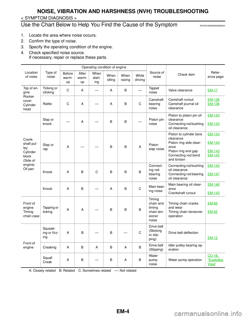
Use the Chart Below to Help You Find the Cause of the Symptom
INFOID:0000000003802223
1. Locate the area where noise occurs.
2. Confirm the type of noise.
3. Specify the operating condition of the engine.
4. Check specified noise source.
If necessary, repair or replace these parts.
A: Closely related B: Related C: Sometimes related —: Not related Location
of noiseType of
noiseOperating condition of engine
Source of
noiseCheck itemRefer-
ence page Before
warm-
upAfter
warm-
upWhen
start-
ingWhen
idlingWhen
racingWhile
driving
Top of en-
gine
Rocker
cover
Cylinder
headTicking or
clickingCA—AB—Tappet
noiseValve clearanceEM-17
Rattle C A — A B CCamshaft
bearing
noiseCamshaft runout
Camshaft journal oil
clearanceEM-136EM-136
Crank-
shaft pul-
ley
Cylinder
block
(Side of
engine)
Oil panSlap or
knock—A—B B—Piston pin
noisePiston to piston pin oil
clearance
Connecting rod bushing
oil clearanceEM-143
EM-143
Slap or
rapA——B B APiston
slap noisePiston to cylinder bore
clearance
Piston ring side clear-
ance
Piston ring end gap
Connecting rod bend
and torsionEM-143EM-143
EM-143
EM-143
Knock A B C B B BConnect-
ing rod
bearing
noiseConnecting rod bushing
oil clearance
Connecting rod bearing
oil clearanceEM-143EM-147
Knock A B — A B CMain bear-
ing noiseMain bearing oil clear-
ance
Crankshaft runoutEM-146
EM-143
Front of
engine
Timing
chain caseTapping or
tickingAA—BBBTiming
chain and
timing
chain ten-
sioner
noiseTiming chain cracks
and wear
Timing chain tensioner
operationEM-65
EM-52
Front of
engineSqueak-
ing or fizz-
ingAB—B—CDrive belt
(Sticking
or slip-
ping)Drive belt deflection
EM-12
CreakingABABABDrive belt
(Slipping)Idler pulley bearing op-
eration
Squall
CreakAB—BABWater
pump
noiseWater pump operationCO-18,
"Exploded
View"
Page 1880 of 5121
PRECAUTIONS
EM-5
< PRECAUTION >
C
D
E
F
G
H
I
J
K
L
MA
EM
N
P O
PRECAUTION
PRECAUTIONS
Precaution for Procedure without Cowl Top CoverINFOID:0000000003802312
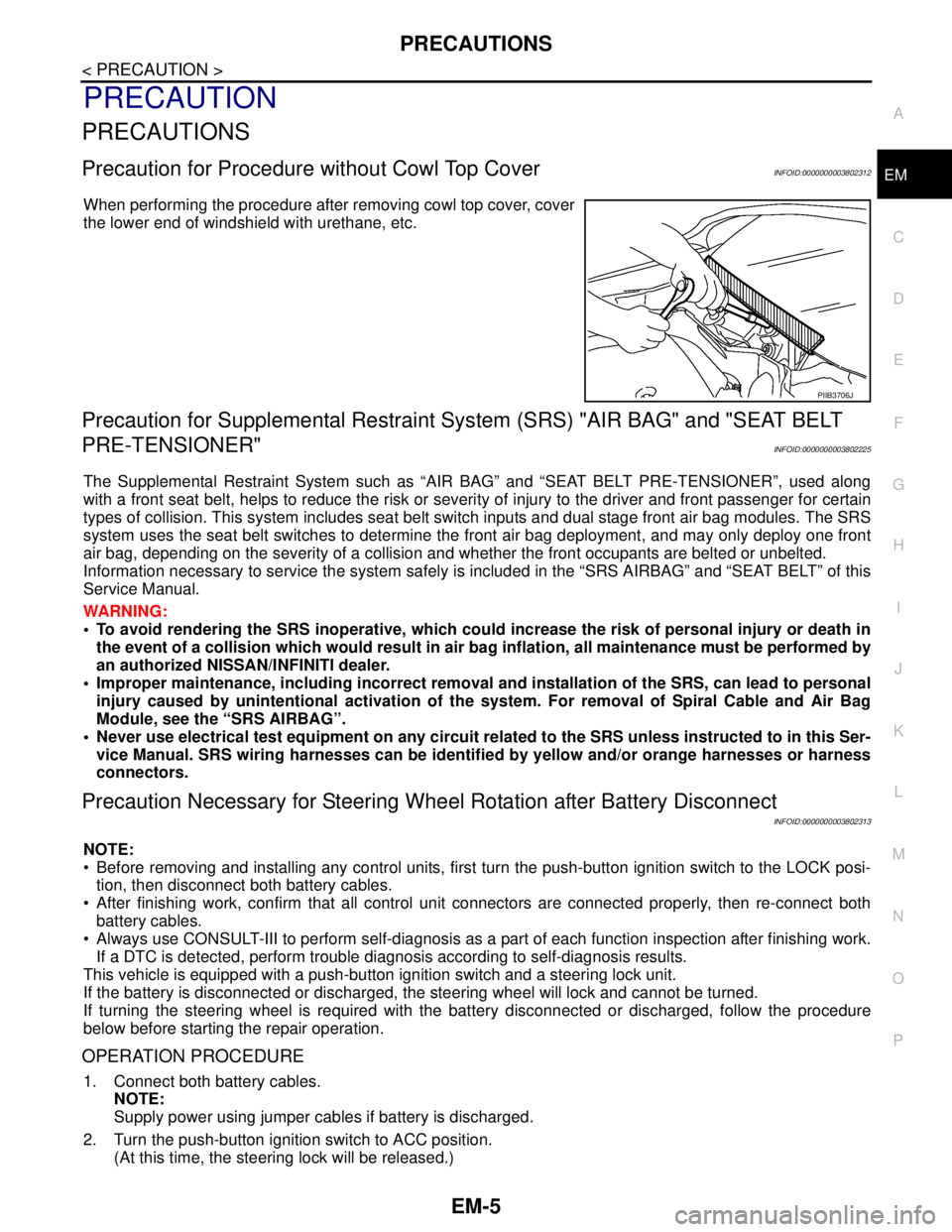
When performing the procedure after removing cowl top cover, cover
the lower end of windshield with urethane, etc.
Precaution for Supplemental Restraint System (SRS) "AIR BAG" and "SEAT BELT
PRE-TENSIONER"
INFOID:0000000003802225
The Supplemental Restraint System such as “AIR BAG” and “SEAT BELT PRE-TENSIONER”, used along
with a front seat belt, helps to reduce the risk or severity of injury to the driver and front passenger for certain
types of collision. This system includes seat belt switch inputs and dual stage front air bag modules. The SRS
system uses the seat belt switches to determine the front air bag deployment, and may only deploy one front
air bag, depending on the severity of a collision and whether the front occupants are belted or unbelted.
Information necessary to service the system safely is included in the “SRS AIRBAG” and “SEAT BELT” of this
Service Manual.
WARNING:
• To avoid rendering the SRS inoperative, which could increase the risk of personal injury or death in
the event of a collision which would result in air bag inflation, all maintenance must be performed by
an authorized NISSAN/INFINITI dealer.
Improper maintenance, including incorrect removal and installation of the SRS, can lead to personal
injury caused by unintentional activation of the system. For removal of Spiral Cable and Air Bag
Module, see the “SRS AIRBAG”.
Never use electrical test equipment on any circuit related to the SRS unless instructed to in this Ser-
vice Manual. SRS wiring harnesses can be identified by yellow and/or orange harnesses or harness
connectors.
Precaution Necessary for Steering Wheel Rotation after Battery Disconnect
INFOID:0000000003802313
NOTE:
Before removing and installing any control units, first turn the push-button ignition switch to the LOCK posi-
tion, then disconnect both battery cables.
After finishing work, confirm that all control unit connectors are connected properly, then re-connect both
battery cables.
Always use CONSULT-III to perform self-diagnosis as a part of each function inspection after finishing work.
If a DTC is detected, perform trouble diagnosis according to self-diagnosis results.
This vehicle is equipped with a push-button ignition switch and a steering lock unit.
If the battery is disconnected or discharged, the steering wheel will lock and cannot be turned.
If turning the steering wheel is required with the battery disconnected or discharged, follow the procedure
below before starting the repair operation.
OPERATION PROCEDURE
1. Connect both battery cables.
NOTE:
Supply power using jumper cables if battery is discharged.
2. Turn the push-button ignition switch to ACC position.
(At this time, the steering lock will be released.)
PIIB3706J
Page 1888 of 5121
DRIVE BELT
EM-13
< ON-VEHICLE MAINTENANCE >
C
D
E
F
G
H
I
J
K
L
MA
EM
N
P O
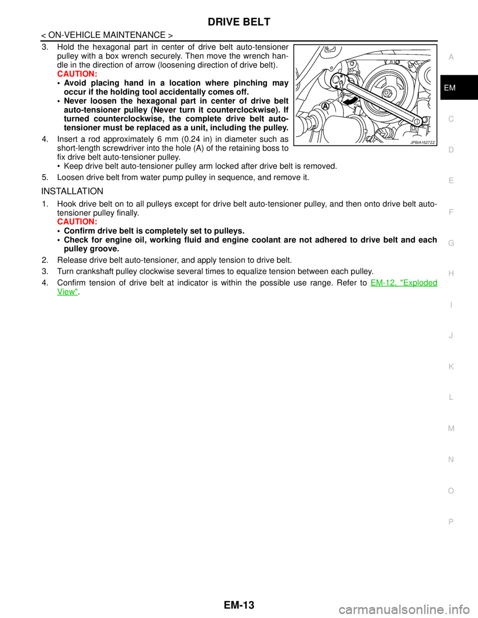
3. Hold the hexagonal part in center of drive belt auto-tensioner
pulley with a box wrench securely. Then move the wrench han-
dle in the direction of arrow (loosening direction of drive belt).
CAUTION:
Avoid placing hand in a location where pinching may
occur if the holding tool accidentally comes off.
Never loosen the hexagonal part in center of drive belt
auto-tensioner pulley (Never turn it counterclockwise). If
turned counterclockwise, the complete drive belt auto-
tensioner must be replaced as a unit, including the pulley.
4. Insert a rod approximately 6 mm (0.24 in) in diameter such as
short-length screwdriver into the hole (A) of the retaining boss to
fix drive belt auto-tensioner pulley.
Keep drive belt auto-tensioner pulley arm locked after drive belt is removed.
5. Loosen drive belt from water pump pulley in sequence, and remove it.
INSTALLATION
1. Hook drive belt on to all pulleys except for drive belt auto-tensioner pulley, and then onto drive belt auto-
tensioner pulley finally.
CAUTION:
Confirm drive belt is completely set to pulleys.
Check for engine oil, working fluid and engine coolant are not adhered to drive belt and each
pulley groove.
2. Release drive belt auto-tensioner, and apply tension to drive belt.
3. Turn crankshaft pulley clockwise several times to equalize tension between each pulley.
4. Confirm tension of drive belt at indicator is within the possible use range. Refer to EM-12, "
Exploded
View".
JPBIA1627ZZ
Page 1922 of 5121
FUEL INJECTOR AND FUEL TUBE
EM-47
< ON-VEHICLE REPAIR >
C
D
E
F
G
H
I
J
K
L
MA
EM
N
P O
Upper and lower O-ring are different. Be careful not to confuse them.
Handle O-ring with bare hands. Never wear gloves.
Lubricate O-ring with new engine oil.
Never clean O-ring with solvent.
Check that O-ring and its mating part are free of foreign material.
When installing O-ring, be careful not to scratch it with tool or fingernails. Also be careful not to
twist or stretch O-ring. If O-ring was stretched while it was being attached, never insert it quickly
into fuel tube.
Insert O-ring straight into fuel injector. Never decenter or twist it.
3. Install fuel injector to fuel tube as follows:
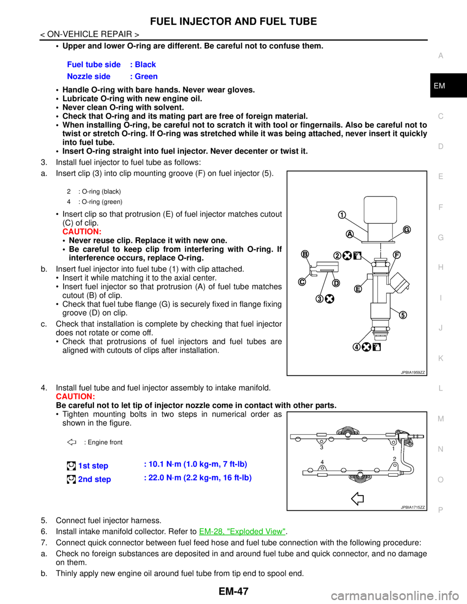
a. Insert clip (3) into clip mounting groove (F) on fuel injector (5).
Insert clip so that protrusion (E) of fuel injector matches cutout
(C) of clip.
CAUTION:
Never reuse clip. Replace it with new one.
Be careful to keep clip from interfering with O-ring. If
interference occurs, replace O-ring.
b. Insert fuel injector into fuel tube (1) with clip attached.
Insert it while matching it to the axial center.
Insert fuel injector so that protrusion (A) of fuel tube matches
cutout (B) of clip.
Check that fuel tube flange (G) is securely fixed in flange fixing
groove (D) on clip.
c. Check that installation is complete by checking that fuel injector
does not rotate or come off.
Check that protrusions of fuel injectors and fuel tubes are
aligned with cutouts of clips after installation.
4. Install fuel tube and fuel injector assembly to intake manifold.
CAUTION:
Be careful not to let tip of injector nozzle come in contact with other parts.
Tighten mounting bolts in two steps in numerical order as
shown in the figure.
5. Connect fuel injector harness.
6. Install intake manifold collector. Refer to EM-28, "
Exploded View".
7. Connect quick connector between fuel feed hose and fuel tube connection with the following procedure:
a. Check no foreign substances are deposited in and around fuel tube and quick connector, and no damage
on them.
b. Thinly apply new engine oil around fuel tube from tip end to spool end.Fuel tube side : Black
Nozzle side : Green
2 : O-ring (black)
4 : O-ring (green)
JPBIA1959ZZ
: Engine front
1st step: 10.1 N·m (1.0 kg-m, 7 ft-lb)
2nd step: 22.0 N·m (2.2 kg-m, 16 ft-lb)
JPBIA1715ZZ
Page 2004 of 5121
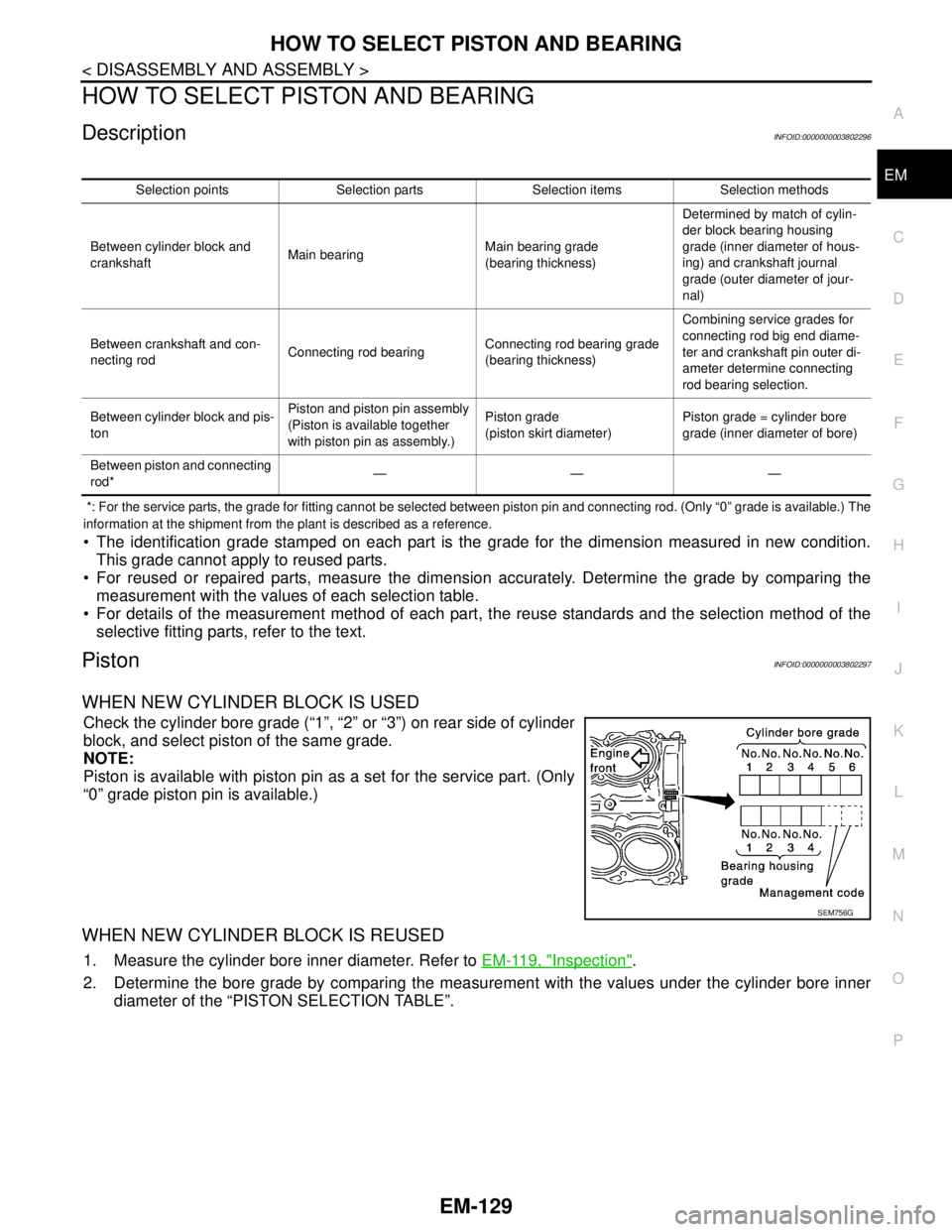
HOW TO SELECT PISTON AND BEARING
EM-129
< DISASSEMBLY AND ASSEMBLY >
C
D
E
F
G
H
I
J
K
L
MA
EM
N
P O
HOW TO SELECT PISTON AND BEARING
DescriptionINFOID:0000000003802296
*: For the service parts, the grade for fitting cannot be selected between piston pin and connecting rod. (Only “0” grade is available.) The
information at the shipment from the plant is described as a reference.
The identification grade stamped on each part is the grade for the dimension measured in new condition.
This grade cannot apply to reused parts.
For reused or repaired parts, measure the dimension accurately. Determine the grade by comparing the
measurement with the values of each selection table.
For details of the measurement method of each part, the reuse standards and the selection method of the
selective fitting parts, refer to the text.
PistonINFOID:0000000003802297
WHEN NEW CYLINDER BLOCK IS USED
Check the cylinder bore grade (“1”, “2” or “3”) on rear side of cylinder
block, and select piston of the same grade.
NOTE:
Piston is available with piston pin as a set for the service part. (Only
“0” grade piston pin is available.)
WHEN NEW CYLINDER BLOCK IS REUSED
1. Measure the cylinder bore inner diameter. Refer to EM-119, "Inspection".
2. Determine the bore grade by comparing the measurement with the values under the cylinder bore inner
diameter of the “PISTON SELECTION TABLE”.
Selection points Selection parts Selection items Selection methods
Between cylinder block and
crankshaftMain bearingMain bearing grade
(bearing thickness)Determined by match of cylin-
der block bearing housing
grade (inner diameter of hous-
ing) and crankshaft journal
grade (outer diameter of jour-
nal)
Between crankshaft and con-
necting rodConnecting rod bearingConnecting rod bearing grade
(bearing thickness)Combining service grades for
connecting rod big end diame-
ter and crankshaft pin outer di-
ameter determine connecting
rod bearing selection.
Between cylinder block and pis-
tonPiston and piston pin assembly
(Piston is available together
with piston pin as assembly.)Piston grade
(piston skirt diameter)Piston grade = cylinder bore
grade (inner diameter of bore)
Between piston and connecting
rod*———
SEM756G
Page 2037 of 5121
![NISSAN TEANA 2008 Service Manual EXL-8
< BASIC INSPECTION >[XENON TYPE]
DIAGNOSIS AND REPAIR WORKFLOW
>> GO TO 2.
2.SYMPTOM CHECK
Check the symptom from the customers information.
>> GO TO 3.
3.BASIC INSPECTION
Check the operation o NISSAN TEANA 2008 Service Manual EXL-8
< BASIC INSPECTION >[XENON TYPE]
DIAGNOSIS AND REPAIR WORKFLOW
>> GO TO 2.
2.SYMPTOM CHECK
Check the symptom from the customers information.
>> GO TO 3.
3.BASIC INSPECTION
Check the operation o](/manual-img/5/57391/w960_57391-2036.png)
EXL-8
< BASIC INSPECTION >[XENON TYPE]
DIAGNOSIS AND REPAIR WORKFLOW
>> GO TO 2.
2.SYMPTOM CHECK
Check the symptom from the customer's information.
>> GO TO 3.
3.BASIC INSPECTION
Check the operation of each part. Check that any symptom occurs other than the interviewed symptom.
>> GO TO 4.
4.SELF-DIAGNOSIS WITH CONSULT-III
Perform the self-diagnosis with CONSULT-III. Check that any DTC is detected.
Is any DTC detected?
YES >> GO TO 5.
NO >> GO TO 6.
5.TROUBLE DIAGNOSIS BY DTC
Perform the trouble diagnosis for the detected DTC. Specify the malfunctioning part.
>> GO TO 9.
6.FAIL-SAFE ACTIVATION CHECK
Check that the symptom is applied to the fail-safe activation.
Does the fail-safe activate?
YES >> GO TO 7.
NO >> GO TO 8.
7.SYSTEM DIAGNOSIS
Perform the system diagnosis for the system that the fail-safe activates. Specify the malfunctioning part.
>> GO TO 9.
8.SYMPTOM DIAGNOSIS
Perform the symptom diagnosis. Specify the malfunctioning part.
>> GO TO 9.
9.MALFUNCTION PART REPAIR
Repair or replace the malfunctioning part.
>> GO TO 10.
10.REPAIR CHECK (SELF-DIAGNOSIS WITH CONSULT-III)
Perform the self-diagnosis with CONSULT-III. Check that any DTC is not detected. Erase DTC if DTC is
detected before the repair. Check that DTC is not detected again.
Is any DTC detected?
YES >> GO TO 5.
NO >> GO TO 11.
11 .REPAIR CHECK (OPERATION CHECK)
Check the operation of each part.
Does it operate normally?
YES >> INSPECTION END
NO >> GO TO 3.
Page 2087 of 5121
![NISSAN TEANA 2008 Service Manual EXL-58
< COMPONENT DIAGNOSIS >[XENON TYPE]
XENON HEADLAMP
XENON HEADLAMP
DescriptionINFOID:0000000003773562
OUTLINE
The lamp light source is by the arch discharge by applying high voltage into the x NISSAN TEANA 2008 Service Manual EXL-58
< COMPONENT DIAGNOSIS >[XENON TYPE]
XENON HEADLAMP
XENON HEADLAMP
DescriptionINFOID:0000000003773562
OUTLINE
The lamp light source is by the arch discharge by applying high voltage into the x](/manual-img/5/57391/w960_57391-2086.png)
EXL-58
< COMPONENT DIAGNOSIS >[XENON TYPE]
XENON HEADLAMP
XENON HEADLAMP
DescriptionINFOID:0000000003773562
OUTLINE
The lamp light source is by the arch discharge by applying high voltage into the xenon gas-filled bulb instead
of the halogen bulb filament.
Sight becomes more natural and brighter because the amount of light are gained adequately and the color of
light is sunshine-like white.
The xenon bulb drops the amount of light, repeats blinking, and illuminates in red if the bulb reaches the ser-
vice life.
ILLUMINATION PRINCIPLE
1. Discharging starts in high voltage pulse between bulb elec-
trodes.
2. Xenon gas is activated by current between electrodes. Pale light
is emitted.
3. The luminous tube (bulb) temperature elevates. Evaporated
halide is activated by discharge. The color of light changes into
white.
NOTE:
Brightness and the color of light may change slightly immediately
after the headlamp turned ON until the xenon bulb becomes sta-
ble. This is not malfunction.
Illumination time lag may occur between right and left. This is not
malfunction.
PRECAUTIONS FOR TROUBLE DIAGNOSIS
Representative malfunction examples are; "Light does not turn ON", "Light blinks", and "Brightness is inade-
quate." The cause often be the xenon bulb. Such malfunctions, however, are occurred occasionally by HID
control unit malfunction or lamp case malfunction. Specify the malfunctioning part with diagnosis procedure.
WARNING:
Never touch the harness, HID control unit, the inside and metal part of lamp when turning the head-
lamp ON or operating the lighting switch.
Never work with wet hands.
CAUTION:
Never perform HID control unit circuit diagnosis with a circuit tester or an equivalent.
Temporarily install the headlamps on the vehicle. Connect the battery to the connector (vehicle side)
when checking ON/OFF status.
Disconnect the battery negative terminal before disconnecting the lamp socket connector or the har-
ness connector.
Check for fusing of the fusible link(s), open around connector, short, disconnection if the symptom
is caused by electric error.
NOTE:
Turn the switch OFF once before turning ON, if the ON/OFF is inoperative.
The xenon bulb drops the amount of light, repeats blinking, and illuminates in red if the bulb reaches the ser-
vice life.
Diagnosis ProcedureINFOID:0000000003773563
1.CHECK XENON BULB
Install the normal bulb to the applicable headlamp. Check that the lighting switch is turned ON.
Is the headlamp turned ON?
YES >> Replace the xenon bulb.
NO >> GO TO 2.
2.CHECK HID CONTROL UNIT
Install the normal HID control unit to the applicable headlamp. Check that the lighting switch is turned ON.
Is the headlamp turned ON?
JPLIA0421GB
Page 2196 of 5121
![NISSAN TEANA 2008 Service Manual NORMAL OPERATING CONDITION
EXL-167
< SYMPTOM DIAGNOSIS >[XENON TYPE]
C
D
E
F
G
H
I
J
K
MA
B
EXL
N
O
P
NORMAL OPERATING CONDITION
DescriptionINFOID:0000000003774368
XENON HEADLAMP
Brightness and the NISSAN TEANA 2008 Service Manual NORMAL OPERATING CONDITION
EXL-167
< SYMPTOM DIAGNOSIS >[XENON TYPE]
C
D
E
F
G
H
I
J
K
MA
B
EXL
N
O
P
NORMAL OPERATING CONDITION
DescriptionINFOID:0000000003774368
XENON HEADLAMP
Brightness and the](/manual-img/5/57391/w960_57391-2195.png)
NORMAL OPERATING CONDITION
EXL-167
< SYMPTOM DIAGNOSIS >[XENON TYPE]
C
D
E
F
G
H
I
J
K
MA
B
EXL
N
O
P
NORMAL OPERATING CONDITION
DescriptionINFOID:0000000003774368
XENON HEADLAMP
Brightness and the color of light may change slightly immediately after turning the headlamp ON until the
xenon bulb becomes stable. This is normal.
Illumination time lag may occur between right and left. This is normal.
AUTO LIGHT SYSTEM
The headlamp may not be turned ON/OFF immediately after passing dark area or bright area (short tunnel,
sky bridge, shadowed area etc.) while using the auto light system. This causes for the control difference. This
is normal.