2008 NISSAN TEANA engine coolant
[x] Cancel search: engine coolantPage 1979 of 5121

EM-104
< DISASSEMBLY AND ASSEMBLY >
CYLINDER HEAD
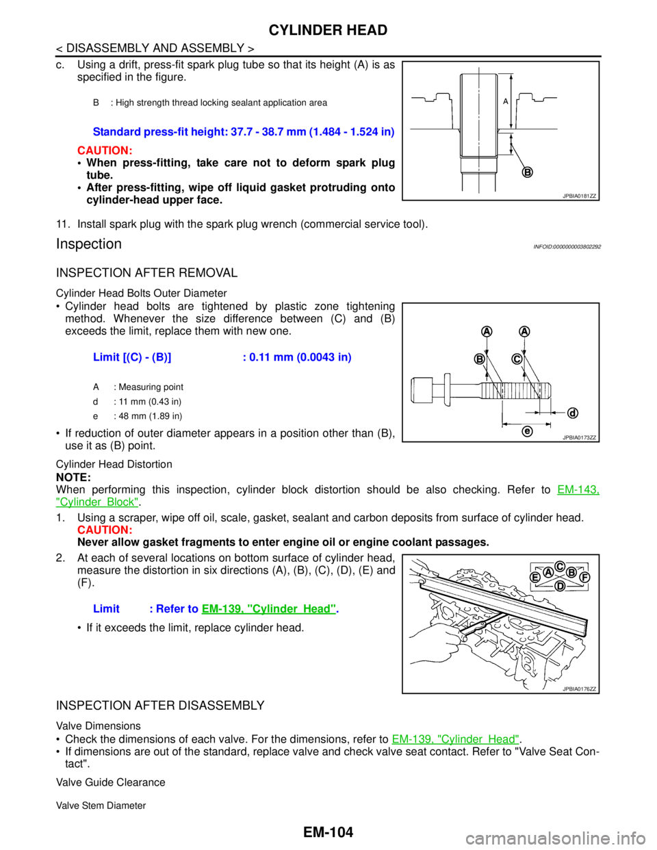
c. Using a drift, press-fit spark plug tube so that its height (A) is as
specified in the figure.
CAUTION:
When press-fitting, take care not to deform spark plug
tube.
After press-fitting, wipe off liquid gasket protruding onto
cylinder-head upper face.
11. Install spark plug with the spark plug wrench (commercial service tool).
InspectionINFOID:0000000003802292
INSPECTION AFTER REMOVAL
Cylinder Head Bolts Outer Diameter
Cylinder head bolts are tightened by plastic zone tightening
method. Whenever the size difference between (C) and (B)
exceeds the limit, replace them with new one.
If reduction of outer diameter appears in a position other than (B),
use it as (B) point.
Cylinder Head Distortion
NOTE:
When performing this inspection, cylinder block distortion should be also checking. Refer to EM-143,
"CylinderBlock".
1. Using a scraper, wipe off oil, scale, gasket, sealant and carbon deposits from surface of cylinder head.
CAUTION:
Never allow gasket fragments to enter engine oil or engine coolant passages.
2. At each of several locations on bottom surface of cylinder head,
measure the distortion in six directions (A), (B), (C), (D), (E) and
(F).
If it exceeds the limit, replace cylinder head.
INSPECTION AFTER DISASSEMBLY
Valve Dimensions
Check the dimensions of each valve. For the dimensions, refer to EM-139, "CylinderHead".
If dimensions are out of the standard, replace valve and check valve seat contact. Refer to "Valve Seat Con-
tact".
Valve Guide Clearance
Valve Stem Diameter
B : High strength thread locking sealant application area
Standard press-fit height: 37.7 - 38.7 mm (1.484 - 1.524 in)
JPBIA0181ZZ
Limit [(C) - (B)] : 0.11 mm (0.0043 in)
A : Measuring point
d : 11 mm (0.43 in)
e : 48 mm (1.89 in)
JPBIA0173ZZ
Limit : Refer to EM-139, "CylinderHead".
JPBIA0176ZZ
Page 1981 of 5121

EM-106
< DISASSEMBLY AND ASSEMBLY >
CYLINDER HEAD
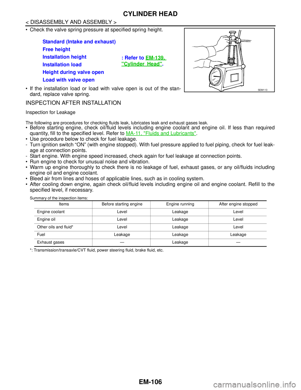
Check the valve spring pressure at specified spring height.
If the installation load or load with valve open is out of the stan-
dard, replace valve spring.
INSPECTION AFTER INSTALLATION
Inspection for Leakage
The following are procedures for checking fluids leak, lubricates leak and exhaust gases leak.
Before starting engine, check oil/fluid levels including engine coolant and engine oil. If less than required
quantity, fill to the specified level. Refer to MA-11, "
Fluids and Lubricants".
Use procedure below to check for fuel leakage.
- Turn ignition switch “ON” (with engine stopped). With fuel pressure applied to fuel piping, check for fuel leak-
age at connection points.
- Start engine. With engine speed increased, check again for fuel leakage at connection points.
Run engine to check for unusual noise and vibration.
Warm up engine thoroughly to check there is no leakage of fuel, exhaust gases, or any oil/fluids including
engine oil and engine coolant.
Bleed air from lines and hoses of applicable lines, such as in cooling system.
After cooling down engine, again check oil/fluid levels including engine oil and engine coolant. Refill to the
specified level, if necessary.
Summary of the inspection items:
*: Transmission/transaxle/CVT fluid, power steering fluid, brake fluid, etc.
Standard (Intake and exhaust)
: Refer to EM-139,
"CylinderHead". Free height
Installation height
Installation load
Height during valve open
Load with valve open
SEM113
Items Before starting engine Engine running After engine stopped
Engine coolant Level Leakage Level
Engine oil Level Leakage Level
Other oils and fluid* Level Leakage Level
Fuel Leakage Leakage Leakage
Exhaust gases — Leakage —
Page 1987 of 5121

EM-112
< DISASSEMBLY AND ASSEMBLY >
CYLINDER BLOCK
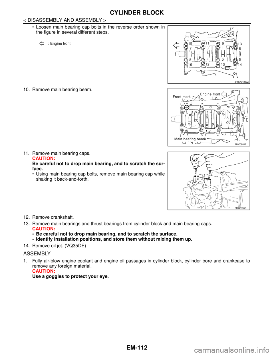
Loosen main bearing cap bolts in the reverse order shown in
the figure in several different steps.
10. Remove main bearing beam.
11. Remove main bearing caps.
CAUTION:
Be careful not to drop main bearing, and to scratch the sur-
face.
Using main bearing cap bolts, remove main bearing cap while
shaking it back-and-forth.
12. Remove crankshaft.
13. Remove main bearings and thrust bearings from cylinder block and main bearing caps.
CAUTION:
Be careful not to drop main bearing, and to scratch the surface.
Identify installation positions, and store them without mixing them up.
14. Remove oil jet. (VQ35DE)
ASSEMBLY
1. Fully air-blow engine coolant and engine oil passages in cylinder block, cylinder bore and crankcase to
remove any foreign material.
CAUTION:
Use a goggles to protect your eye.
: Engine front
JPBIA0439ZZ
PBIC0881E
EMQ0195D
Page 1998 of 5121

CYLINDER BLOCK
EM-123
< DISASSEMBLY AND ASSEMBLY >
C
D
E
F
G
H
I
J
K
L
MA
EM
N
P O
Unit: mm (in)
*: After installing in connecting rod
CYLINDER BLOCK DISTORTION
Using a scraper, remove gasket on the cylinder block surface, and also remove engine oil, scale, carbon, or
other contamination.
CAUTION:
Be careful not to allow gasket flakes to enter engine oil or engine coolant passages.
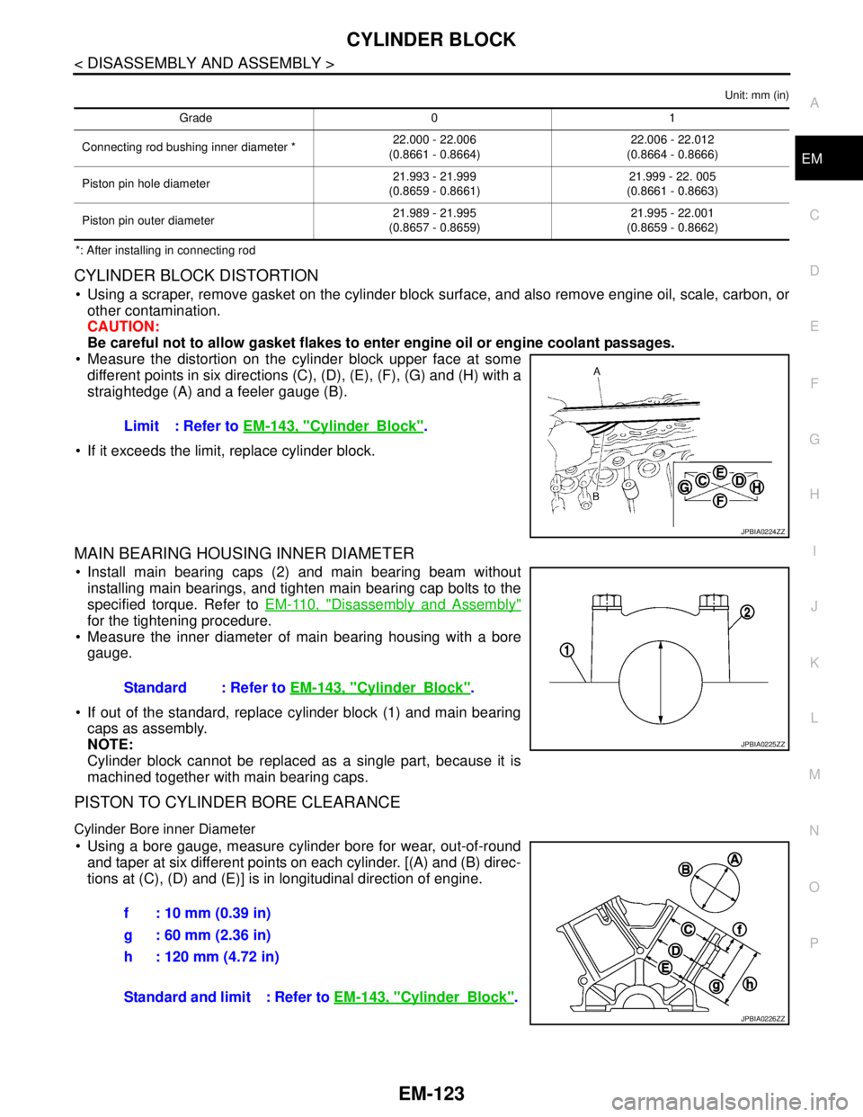
Measure the distortion on the cylinder block upper face at some
different points in six directions (C), (D), (E), (F), (G) and (H) with a
straightedge (A) and a feeler gauge (B).
If it exceeds the limit, replace cylinder block.
MAIN BEARING HOUSING INNER DIAMETER
Install main bearing caps (2) and main bearing beam without
installing main bearings, and tighten main bearing cap bolts to the
specified torque. Refer to EM-110, "
Disassembly and Assembly"
for the tightening procedure.
Measure the inner diameter of main bearing housing with a bore
gauge.
If out of the standard, replace cylinder block (1) and main bearing
caps as assembly.
NOTE:
Cylinder block cannot be replaced as a single part, because it is
machined together with main bearing caps.
PISTON TO CYLINDER BORE CLEARANCE
Cylinder Bore inner Diameter
Using a bore gauge, measure cylinder bore for wear, out-of-round
and taper at six different points on each cylinder. [(A) and (B) direc-
tions at (C), (D) and (E)] is in longitudinal direction of engine.
Grade 0 1
Connecting rod bushing inner diameter *22.000 - 22.006
(0.8661 - 0.8664)22.006 - 22.012
(0.8664 - 0.8666)
Piston pin hole diameter21.993 - 21.999
(0.8659 - 0.8661)21.999 - 22. 005
(0.8661 - 0.8663)
Piston pin outer diameter21.989 - 21.995
(0.8657 - 0.8659)21.995 - 22.001
(0.8659 - 0.8662)
Limit : Refer to EM-143, "CylinderBlock".
JPBIA0224ZZ
Standard : Refer to EM-143, "CylinderBlock".
JPBIA0225ZZ
f : 10 mm (0.39 in)
g : 60 mm (2.36 in)
h : 120 mm (4.72 in)
Standard and limit : Refer to EM-143, "
CylinderBlock".
JPBIA0226ZZ
Page 2171 of 5121
![NISSAN TEANA 2008 Service Manual EXL-142
< ECU DIAGNOSIS >[XENON TYPE]
IPDM E/R (INTELLIGENT POWER DISTRIBUTION MODULE ENGINE ROOM)
IPDM E/R (INTELLIGENT POWER DISTRIBUTION MODULE ENGINE
ROOM)
Reference ValueINFOID:0000000003894273
V NISSAN TEANA 2008 Service Manual EXL-142
< ECU DIAGNOSIS >[XENON TYPE]
IPDM E/R (INTELLIGENT POWER DISTRIBUTION MODULE ENGINE ROOM)
IPDM E/R (INTELLIGENT POWER DISTRIBUTION MODULE ENGINE
ROOM)
Reference ValueINFOID:0000000003894273
V](/manual-img/5/57391/w960_57391-2170.png)
EXL-142
< ECU DIAGNOSIS >[XENON TYPE]
IPDM E/R (INTELLIGENT POWER DISTRIBUTION MODULE ENGINE ROOM)
IPDM E/R (INTELLIGENT POWER DISTRIBUTION MODULE ENGINE
ROOM)
Reference ValueINFOID:0000000003894273
VALUES ON THE DIAGNOSIS TOOL
Monitor Item Condition Value/Status
MOTOR FAN REQ Engine idle speedChanges depending on engine
coolant temperature, air conditioner
operation status, vehicle speed,
etc.1/2/3/4
AC COMP REQ Engine runningA/C switch OFF Off
A/C switch ON
(Compressor is operating)On
TAIL&CLR REQLighting switch OFF Off
Lighting switch 1ST, 2ND, HI or AUTO (Light is illuminated) On
HL LO REQLighting switch OFF Off
Lighting switch 2ND HI or AUTO (Light is illuminated) On
HL HI REQLighting switch OFF Off
Lighting switch HI On
FR FOG REQLighting switch 2ND or
AUTO (Light is illuminated)Front fog lamp switch OFF Off
Front fog lamp switch ON On
FR WIP REQ Ignition switch ONFront wiper switch OFF Stop
Front wiper switch INT 1LOW
Front wiper switch LO Low
Front wiper switch HI Hi
WIP AUTO STOP Ignition switch ONFront wiper stop position STOP P
Any position other than front wiper
stop positionACT P
WIP PROT Ignition switch ONFront wiper operates normally Off
Front wiper stops at fail-safe opera-
tionBLOCK
IGN RLY1 -REQIgnition switch OFF or ACC Off
Ignition switch ON On
IGN RLYIgnition switch OFF or ACC Off
Ignition switch ON On
PUSH SWRelease the push-button ignition switch Off
Press the push-button ignition switch On
INTER/NP SW Ignition switch ONSelector lever in any position other
than P or NOff
Selector lever in P or N position On
ST RLY CONTIgnition switch ON Off
At engine cranking On
IHBT RLY -REQIgnition switch ON Off
At engine cranking On
Page 2202 of 5121
![NISSAN TEANA 2008 Service Manual HEADLAMP AIMING ADJUSTMENT
EXL-173
< ON-VEHICLE MAINTENANCE >[XENON TYPE]
C
D
E
F
G
H
I
J
K
MA
B
EXL
N
O
P
ON-VEHICLE MAINTENANCE
HEADLAMP AIMING ADJUSTMENT
DescriptionINFOID:0000000003774534
PREPARAT NISSAN TEANA 2008 Service Manual HEADLAMP AIMING ADJUSTMENT
EXL-173
< ON-VEHICLE MAINTENANCE >[XENON TYPE]
C
D
E
F
G
H
I
J
K
MA
B
EXL
N
O
P
ON-VEHICLE MAINTENANCE
HEADLAMP AIMING ADJUSTMENT
DescriptionINFOID:0000000003774534
PREPARAT](/manual-img/5/57391/w960_57391-2201.png)
HEADLAMP AIMING ADJUSTMENT
EXL-173
< ON-VEHICLE MAINTENANCE >[XENON TYPE]
C
D
E
F
G
H
I
J
K
MA
B
EXL
N
O
P
ON-VEHICLE MAINTENANCE
HEADLAMP AIMING ADJUSTMENT
DescriptionINFOID:0000000003774534
PREPARATION BEFORE ADJUSTING
NOTE:
For details, refer to the regulations in your own country.
Perform aiming if the vehicle front body has been repaired and/or the headlamp assembly has been
replaced.
Before performing aiming adjustment, check the following. Adjust the tire pressure to the specification.
Fill with fuel, engine coolant and each oil.
Maintain the unloaded vehicle condition. (Remove luggage from the passenger compartment and the trunk
room.)
NOTE:
Do not remove the temporary tire, jack and on-vehicle tool.
Wipe out dirt on the headlamp.
CAUTION:
Never use organic solvent (thinner, gasoline etc.)
Ride alone on the driver seat.
AIMING ADJUSTMENT SCREW
JPLIA1085ZZ
Page 2207 of 5121
![NISSAN TEANA 2008 Service Manual EXL-178
< ON-VEHICLE MAINTENANCE >[XENON TYPE]
FRONT FOG LAMP AIMING ADJUSTMENT
FRONT FOG LAMP AIMING ADJUSTMENT
DescriptionINFOID:0000000003773617
PREPARATION BEFORE ADJUSTING
NOTE:
For details, re NISSAN TEANA 2008 Service Manual EXL-178
< ON-VEHICLE MAINTENANCE >[XENON TYPE]
FRONT FOG LAMP AIMING ADJUSTMENT
FRONT FOG LAMP AIMING ADJUSTMENT
DescriptionINFOID:0000000003773617
PREPARATION BEFORE ADJUSTING
NOTE:
For details, re](/manual-img/5/57391/w960_57391-2206.png)
EXL-178
< ON-VEHICLE MAINTENANCE >[XENON TYPE]
FRONT FOG LAMP AIMING ADJUSTMENT
FRONT FOG LAMP AIMING ADJUSTMENT
DescriptionINFOID:0000000003773617
PREPARATION BEFORE ADJUSTING
NOTE:
For details, refer to the regulations in your own country.
Before performing aiming adjustment, check the following.
Adjust the tire pressure to the specification.
Fill with fuel, engine coolant and each oil.
Maintain the unloaded vehicle condition. (Remove luggage from the passenger compartment and the lug-
gage room.)
NOTE:
Do not remove the temporary tire, jack and on-vehicle tool.
Wipe out dirt on the headlamp.
CAUTION:
Never use organic solvent (thinner, gasoline etc.)
Ride alone on the driver seat.
AIMING ADJUSTMENT SCREW
Turn the aiming adjusting screw for adjustment.
For the position and direction of the adjusting screw, refer to the
figure.
NOTE:
A screwdriver or hexagonal wrench [6 mm (0.24 in)] can be used
for adjustment.
Aiming Adjustment ProcedureINFOID:0000000003773618
1. Place the screen.
NOTE:
Stop the vehicle facing the wall.
Place the board on a plain road vertically.
2. Face the vehicle with the screen. Maintain 10 m (32.8 ft) between the front fog lamp center and the
screen.
3. Start the engine. Illuminate the front fog lamp.
CAUTION:
Never cover the lens surface with a tape etc. The lens is made of resin.
NOTE:
Shut off the headlamp light with the board to prevent from illuminating the adjustment screen.
4. Adjust the cutoff line height (A) with the aiming adjustment screw so that the distance (X) between the hor-
izontal center line of front fog lamp (H) and (A) becomes 200 mm (7.87 in).
Front fog lamp light distribution on the screen
A: UP
B: DOWN
JPLIA1086ZZ
JPLIA0008ZZ
Page 2343 of 5121
![NISSAN TEANA 2008 Service Manual EXL-314
< ECU DIAGNOSIS >[HALOGEN TYPE]
IPDM E/R (INTELLIGENT POWER DISTRIBUTION MODULE ENGINE ROOM)
IPDM E/R (INTELLIGENT POWER DISTRIBUTION MODULE ENGINE
ROOM)
Reference ValueINFOID:0000000003894350 NISSAN TEANA 2008 Service Manual EXL-314
< ECU DIAGNOSIS >[HALOGEN TYPE]
IPDM E/R (INTELLIGENT POWER DISTRIBUTION MODULE ENGINE ROOM)
IPDM E/R (INTELLIGENT POWER DISTRIBUTION MODULE ENGINE
ROOM)
Reference ValueINFOID:0000000003894350](/manual-img/5/57391/w960_57391-2342.png)
EXL-314
< ECU DIAGNOSIS >[HALOGEN TYPE]
IPDM E/R (INTELLIGENT POWER DISTRIBUTION MODULE ENGINE ROOM)
IPDM E/R (INTELLIGENT POWER DISTRIBUTION MODULE ENGINE
ROOM)
Reference ValueINFOID:0000000003894350
VALUES ON THE DIAGNOSIS TOOL
Monitor Item Condition Value/Status
MOTOR FAN REQ Engine idle speedChanges depending on engine
coolant temperature, air conditioner
operation status, vehicle speed,
etc.1/2/3/4
AC COMP REQ Engine runningA/C switch OFF Off
A/C switch ON
(Compressor is operating)On
TAIL&CLR REQLighting switch OFF Off
Lighting switch 1ST, 2ND, HI or AUTO (Light is illuminated) On
HL LO REQLighting switch OFF Off
Lighting switch 2ND HI or AUTO (Light is illuminated) On
HL HI REQLighting switch OFF Off
Lighting switch HI On
FR FOG REQLighting switch 2ND or
AUTO (Light is illuminated)Front fog lamp switch OFF Off
Front fog lamp switch ON On
FR WIP REQ Ignition switch ONFront wiper switch OFF Stop
Front wiper switch INT 1LOW
Front wiper switch LO Low
Front wiper switch HI Hi
WIP AUTO STOP Ignition switch ONFront wiper stop position STOP P
Any position other than front wiper
stop positionACT P
WIP PROT Ignition switch ONFront wiper operates normally Off
Front wiper stops at fail-safe opera-
tionBLOCK
IGN RLY1 -REQIgnition switch OFF or ACC Off
Ignition switch ON On
IGN RLYIgnition switch OFF or ACC Off
Ignition switch ON On
PUSH SWRelease the push-button ignition switch Off
Press the push-button ignition switch On
INTER/NP SW Ignition switch ONSelector lever in any position other
than P or NOff
Selector lever in P or N position On
ST RLY CONTIgnition switch ON Off
At engine cranking On
IHBT RLY -REQIgnition switch ON Off
At engine cranking On