2008 NISSAN TEANA engine coolant
[x] Cancel search: engine coolantPage 2365 of 5121
![NISSAN TEANA 2008 Service Manual EXL-336
< ON-VEHICLE MAINTENANCE >[HALOGEN TYPE]
HEADLAMP AIMING ADJUSTMENT
ON-VEHICLE MAINTENANCE
HEADLAMP AIMING ADJUSTMENT
DescriptionINFOID:0000000003829238
PREPARATION BEFORE ADJUSTING
NOTE:
Fo NISSAN TEANA 2008 Service Manual EXL-336
< ON-VEHICLE MAINTENANCE >[HALOGEN TYPE]
HEADLAMP AIMING ADJUSTMENT
ON-VEHICLE MAINTENANCE
HEADLAMP AIMING ADJUSTMENT
DescriptionINFOID:0000000003829238
PREPARATION BEFORE ADJUSTING
NOTE:
Fo](/manual-img/5/57391/w960_57391-2364.png)
EXL-336
< ON-VEHICLE MAINTENANCE >[HALOGEN TYPE]
HEADLAMP AIMING ADJUSTMENT
ON-VEHICLE MAINTENANCE
HEADLAMP AIMING ADJUSTMENT
DescriptionINFOID:0000000003829238
PREPARATION BEFORE ADJUSTING
NOTE:
For details, refer to the regulations in your own country.
Perform aiming if the vehicle front body has been repaired and/or the headlamp assembly has been
replaced.
Before performing aiming adjustment, check the following. Adjust the tire pressure to the specification.
Fill with fuel, engine coolant and each oil.
Maintain the unloaded vehicle condition. (Remove luggage from the passenger compartment and the trunk
room.)
NOTE:
Do not remove the temporary tire, jack and on-vehicle tool.
Wipe out dirt on the headlamp.
CAUTION:
Never use organic solvent (thinner, gasoline etc.)
Ride alone on the driver seat.
Headlamp aiming switch sets to “0”.
AIMING ADJUSTMENT SCREW
JPLIA1104ZZ
Page 2370 of 5121
![NISSAN TEANA 2008 Service Manual FRONT FOG LAMP AIMING ADJUSTMENT
EXL-341
< ON-VEHICLE MAINTENANCE >[HALOGEN TYPE]
C
D
E
F
G
H
I
J
K
MA
B
EXL
N
O
P
FRONT FOG LAMP AIMING ADJUSTMENT
DescriptionINFOID:0000000003894358
PREPARATION BEFOR NISSAN TEANA 2008 Service Manual FRONT FOG LAMP AIMING ADJUSTMENT
EXL-341
< ON-VEHICLE MAINTENANCE >[HALOGEN TYPE]
C
D
E
F
G
H
I
J
K
MA
B
EXL
N
O
P
FRONT FOG LAMP AIMING ADJUSTMENT
DescriptionINFOID:0000000003894358
PREPARATION BEFOR](/manual-img/5/57391/w960_57391-2369.png)
FRONT FOG LAMP AIMING ADJUSTMENT
EXL-341
< ON-VEHICLE MAINTENANCE >[HALOGEN TYPE]
C
D
E
F
G
H
I
J
K
MA
B
EXL
N
O
P
FRONT FOG LAMP AIMING ADJUSTMENT
DescriptionINFOID:0000000003894358
PREPARATION BEFORE ADJUSTING
NOTE:
For details, refer to the regulations in your own country.
Before performing aiming adjustment, check the following.
Adjust the tire pressure to the specification.
Fill with fuel, engine coolant and each oil.
Maintain the unloaded vehicle condition. (Remove luggage from the passenger compartment and the lug-
gage room.)
NOTE:
Do not remove the temporary tire, jack and on-vehicle tool.
Wipe out dirt on the headlamp.
CAUTION:
Never use organic solvent (thinner, gasoline etc.)
Ride alone on the driver seat.
AIMING ADJUSTMENT SCREW
Turn the aiming adjusting screw for adjustment.
For the position and direction of the adjusting screw, refer to the
figure.
NOTE:
A screwdriver or hexagonal wrench [6 mm (0.24 in)] can be used
for adjustment.
Aiming Adjustment ProcedureINFOID:0000000003894359
1. Place the screen.
NOTE:
Stop the vehicle facing the wall.
Place the board on a plain road vertically.
2. Face the vehicle with the screen. Maintain 10 m (32.8 ft) between the front fog lamp center and the
screen.
3. Start the engine. Illuminate the front fog lamp.
CAUTION:
Never cover the lens surface with a tape etc. The lens is made of resin.
NOTE:
Shut off the headlamp light with the board to prevent from illuminating the adjustment screen.
4. Adjust the cutoff line height (A) with the aiming adjustment screw so that the distance (X) between the hor-
izontal center line of front fog lamp (H) and (A) becomes 200 mm (7.87 in).
Front fog lamp light distribution on the screen
A: UP
B: DOWN
JPLIA1086ZZ
JPLIA0008ZZ
Page 2478 of 5121

FSU-4
< PRECAUTION >
PRECAUTIONS
Precaution for Procedure without Cowl Top Cover
INFOID:0000000003890157
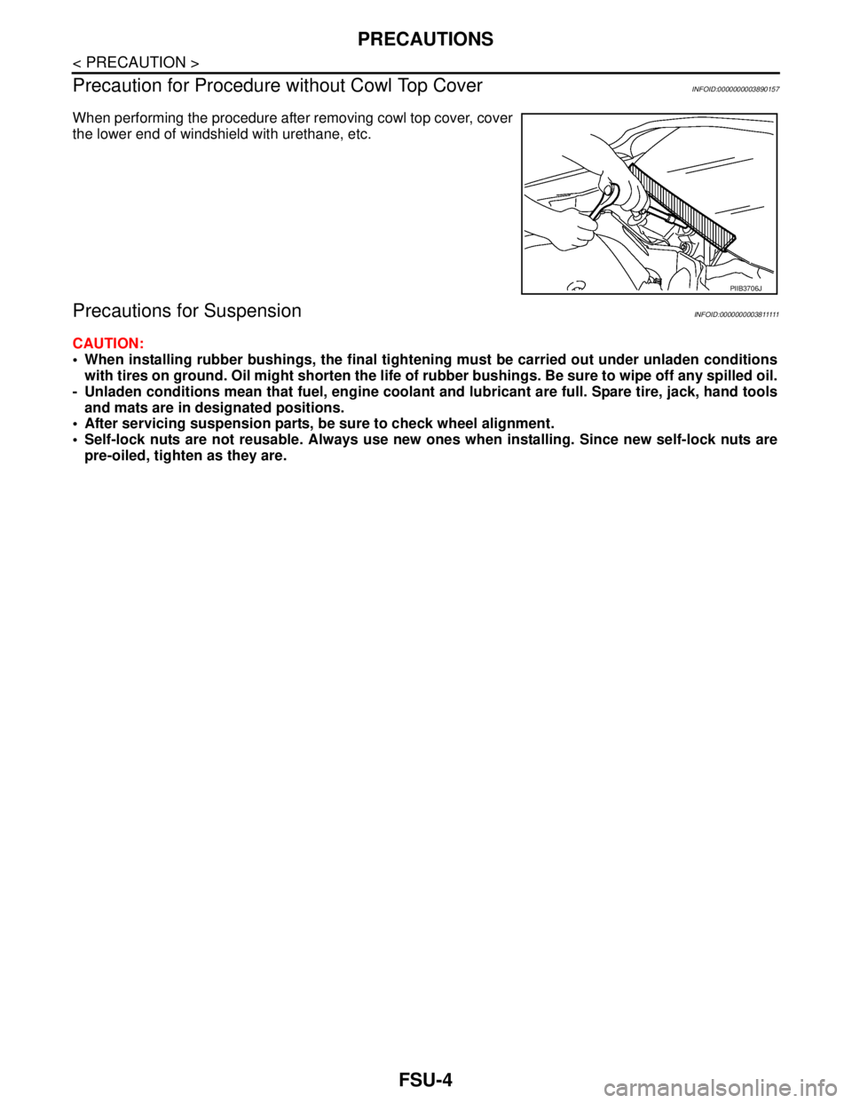
When performing the procedure after removing cowl top cover, cover
the lower end of windshield with urethane, etc.
Precautions for SuspensionINFOID:0000000003811111
CAUTION:
When installing rubber bushings, the final tightening must be carried out under unladen conditions
with tires on ground. Oil might shorten the life of rubber bushings. Be sure to wipe off any spilled oil.
- Unladen conditions mean that fuel, engine coolant and lubricant are full. Spare tire, jack, hand tools
and mats are in designated positions.
After servicing suspension parts, be sure to check wheel alignment.
Self-lock nuts are not reusable. Always use new ones when installing. Since new self-lock nuts are
pre-oiled, tighten as they are.
PIIB3706J
Page 2481 of 5121

WHEEL ALIGNMENT
FSU-7
< ON-VEHICLE MAINTENANCE >
C
D
F
G
H
I
J
K
L
MA
B
FSU
N
O
P
WHEEL ALIGNMENT
Wheel Alignment InspectionINFOID:0000000003812473
INSPECTION
Description
CAUTION:
Camber, caster, kingpin inclination angles cannot be adjusted.
If camber, caster, or kingpin inclination angle exceeds the standard value, check front suspension
parts for wear and damage. Replace suspect parts if a malfunction is detected.
Kingpin inclination angle is reference value, no inspection is required.
Measure wheel alignment under unladen conditions.
NOTE:
“Unladen conditions” means that fuel, engine coolant, and lubricant are full. Spare tire, jack, hand tools and
mats are in designated positions.
Preliminary Check
Check the following:
Tires for improper air pressure and wear
Road wheels for runout: Refer to WT-2, "
Inspection".
Wheel bearing axial end play: Refer to FA X - 6 , "
Inspection".
Transverse link ball joint axial end play: Refer to FSU-11, "
Inspection".
Strut operation.
Each mounting part of axle and suspension for looseness and deformation
Each of suspension member and transverse link for cracks, deformation and other damage
Vehicle height (posture)
CAMBER, CASTER, AND KINGPIN INCLINATION ANGLES
Camber, caster, kingpin inclination angles cannot be adjusted.
Before inspection, mount front wheels onto turning radius gauge. Mount rear wheels onto a stand at the
same height so that vehicle remains horizontal.
Using a CCK Gauge
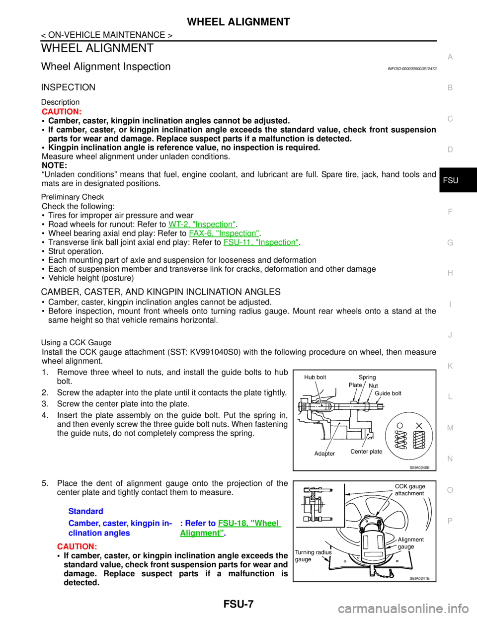
Install the CCK gauge attachment (SST: KV991040S0) with the following procedure on wheel, then measure
wheel alignment.
1. Remove three wheel to nuts, and install the guide bolts to hub
bolt.
2. Screw the adapter into the plate until it contacts the plate tightly.
3. Screw the center plate into the plate.
4. Insert the plate assembly on the guide bolt. Put the spring in,
and then evenly screw the three guide bolt nuts. When fastening
the guide nuts, do not completely compress the spring.
5. Place the dent of alignment gauge onto the projection of the
center plate and tightly contact them to measure.
CAUTION:
If camber, caster, or kingpin inclination angle exceeds the
standard value, check front suspension parts for wear and
damage. Replace suspect parts if a malfunction is
detected.
SEIA0240E
Standard
Camber, caster, kingpin in-
clination angles: Refer to FSU-18, "
Wheel
Alignment".
SEIA0241E
Page 2492 of 5121

FSU-18
< SERVICE DATA AND SPECIFICATIONS (SDS)
SERVICE DATA AND SPECIFICATIONS (SDS)
SERVICE DATA AND SPECIFICATIONS (SDS)
SERVICE DATA AND SPECIFICATIONS (SDS)
Wheel AlignmentINFOID:0000000003811129
Measure value under unladen* conditions.
*: Fuel, engine coolant and lubricant are full. Spare tire, jack, hand tools and mats are in designated positions.
Ball JointINFOID:0000000003811130
Wheel HeightINFOID:0000000003811131
Item Standard
Camber
Degree minute (Decimal degree)Minimum –1° 10′ (–1.16°)
Nominal –0° 25′ (–0.42°)
Maximum 0° 20′ (0.33°)
Left and right difference 0° 45′ (0.75°) or less
Caster
Degree minute (Decimal degree)Minimum 4° 10′ (4.17°)
Nominal 4° 55′ (4.92°)
Maximum 5° 40′ (5.66°)
Left and right difference 0° 45′ (0.75°) or less
Kingpin inclination
Degree minute (Decimal degree)Minimum 11° 55′ (11.92°)
Nominal 12° 40′ (12.67°)
Maximum 13° 25′ (13.41°)
To t a l t o e -
inDistanceMinimum In 0.5 mm (0.020 in)
Nominal In 1.5 mm (0.059 in)
Maximum In 2.5 mm (0.098 in)
Angle (left wheel or right wheel)
Degree minute (Decimal degree)Minimum In 0° 02′ (0.04°)
Nominal In 0° 04
′ (0.07°)
Maximum In 0° 06′ (0.10°)
Item Standard
Swing torque Transverse link 0.5 – 4.9 N·m (0.06 – 0.49 kg-m, 5 – 43 in-lb)
Measurement on spring balance Transverse link 11.1 – 108.9 N (1.2 – 11.1 kg, 3 – 24 lb)
Rotating torque Transverse link 0.5 – 3.4 N·m (0.06 – 0.34 kg-m, 5 – 30 in-lb)
Axial end play0.1 mm (0.004 in)
Tire size 205/65R16 215/55R17
Engine VQ25DE VQ35DE
Grade 250XE 250XL-V6 250XV-V6 350XV-V6
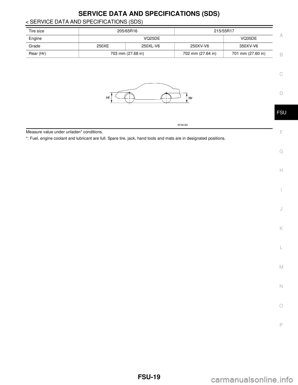
Front (Hf) 712 mm (28.03 in) 711 mm (27.99 in) 710 mm (27.95 in)
Page 2493 of 5121

SERVICE DATA AND SPECIFICATIONS (SDS)
FSU-19
< SERVICE DATA AND SPECIFICATIONS (SDS)
C
D
F
G
H
I
J
K
L
MA
B
FSU
N
O
P
Measure value under unladen* conditions.
*: Fuel, engine coolant and lubricant are full. Spare tire, jack, hand tools and mats are in designated positions.Rear (Hr) 703 mm (27.68 in) 702 mm (27.64 in) 701 mm (27.60 in) Tire size 205/65R16 215/55R17
Engine VQ25DE VQ35DE
Grade 250XE 250XL-V6 250XV-V6 350XV-V6
SFA818A
Page 2510 of 5121

TERMINOLOGY
GI-17
< HOW TO USE THIS MANUAL >
C
D
E
F
G
H
I
J
K
L
MB
GI
N
O
PTERMINOLOGY
SAE J1930 Terminology ListINFOID:0000000003852771
All emission related terms used in this publication in accordance with SAE J1930 are listed. Accordingly, new
terms, new acronyms/abbreviations and old terms are listed in the following chart.
NEW TERMNEW ACRONYM /
ABBREVIATIONOLD TERM
Air cleaner ACL Air cleaner
Barometric pressure BARO ***
Barometric pressure sensor-BCDD BAROS-BCDD BCDD
Camshaft position CMP ***
Camshaft position sensor CMPS Crank angle sensor
Canister *** Canister
Carburetor CARB Carburetor
Charge air cooler CAC Intercooler
Closed loop CL Closed loop
Closed throttle position switch CTP switch Idle switch
Clutch pedal position switch CPP switch Clutch switch
Continuous fuel injection system CFI system ***
Continuous trap oxidizer system CTOX system ***
Crankshaft position CKP ***
Crankshaft position sensor CKPS ***
Data link connector DLC ***
Diagnostic test mode DTM Diagnostic mode
Diagnostic test mode selector DTM selector Diagnostic mode selector
Diagnostic test mode I DTM I Mode I
Diagnostic test mode II DTM II Mode II
Diagnostic trouble code DTC Malfunction code
Direct fuel injection system DFI system ***
Distributor ignition system DI system Ignition timing control
Early fuel evaporation-mixture heater EFE-mixture heater Mixture heater
Early fuel evaporation system EFE system Mixture heater control
Electrically erasable programmable read
only memoryEEPROM ***
Electronic ignition system EI system Ignition timing control
Engine control EC ***
Engine control module ECM ECCS control unit
Engine coolant temperature ECT Engine temperature
Engine coolant temperature sensor ECTS Engine temperature sensor
Engine modification EM ***
Engine speed RPM Engine speed
Erasable programmable read only memory EPROM ***
Evaporative emission canister EVAP canister Canister
Evaporative emission system EVAP system Canister control solenoid valve
Exhaust gas recirculation valve EGR valve EGR valve
Page 2662 of 5121
![NISSAN TEANA 2008 Service Manual HAC-34
< FUNCTION DIAGNOSIS >[WITHOUT 7 INCH DISPLAY]
BLOWER MOTOR CONTROL SYSTEM
BLOWER MOTOR CONTROL SYSTEM
System DiagramINFOID:0000000003846315
System DescriptionINFOID:0000000003846316
Blower spe NISSAN TEANA 2008 Service Manual HAC-34
< FUNCTION DIAGNOSIS >[WITHOUT 7 INCH DISPLAY]
BLOWER MOTOR CONTROL SYSTEM
BLOWER MOTOR CONTROL SYSTEM
System DiagramINFOID:0000000003846315
System DescriptionINFOID:0000000003846316
Blower spe](/manual-img/5/57391/w960_57391-2661.png)
HAC-34
< FUNCTION DIAGNOSIS >[WITHOUT 7 INCH DISPLAY]
BLOWER MOTOR CONTROL SYSTEM
BLOWER MOTOR CONTROL SYSTEM
System DiagramINFOID:0000000003846315
System DescriptionINFOID:0000000003846316
Blower speed is automatically controlled by the temperature setting, ambient temperature, in-vehicle tempera-
ture, intake temperature, amount of sunload and air mix door position.
By pressing the AUTO switch, the blower motor starts to gradually increase air flow volume.
When engine coolant temperature is low, the blower motor operation is delayed to prevent cool air from flow-
ing.
SYSTEM OPERATION
System Operation
For air flow, the manual selection (1-7) with the fan control dial has priority.
If the AUTO switch is pressed or if the DEF switch is pressed while in the OFF condition, it changes to the
automatic control by A/C auto amp.
When increasing the air flow, it changes the duty ratio of the blower motor drive signal to prevent the air flow
from suddenly increasing.
There are the following types of air flow control: starting air flow control, starting air flow control at low cool-
ant temperature, starting air flow control at high in-vehicle temperature, and air flow control at actuator oper-
ation in addition to manual control, normal automatic air flow control.
Normal Automatic Air Flow Control
When the target temperature is set by the temperature control switch of A/C control, the A/C auto amp. per-
forms the calculation and decides the target according to the signal from each sensor.
The A/C auto amp. changes the duty ratio of blower motor drive signal and controls the air flow continuously
so that the air flow becomes the target air flow.
The minimum air flow will change according to the sunload when the air discharge outlet is VENT or B/L.
Fan Speed Control Specification
JPIIA0502GB
JPIIA0635GB