Page 1486 of 2771
EC-412
< SERVICE INFORMATION >
DTC P1217 ENGINE OVER TEMPERATURE
DTC P1217 ENGINE OVER TEMPERATURE
System DescriptionINFOID:0000000001702929
SYSTEM DESCRIPTION
NOTE:
•If DTC P1217 is displayed with DTC U1000 or U1001, first perform the trouble diagnosis for DTC
U1000, U1001. Refer to EC-143
.
•If DTC P1217 is displayed with DTC U1010, first perform the trouble diagnosis for DTC U1010. Refer
to EC-145
.
Cooling Fan Control
*1: The ECM determines the start signal status by the signals of engine speed and battery voltage.
*2: This signal is sent to ECM through CAN communication line.
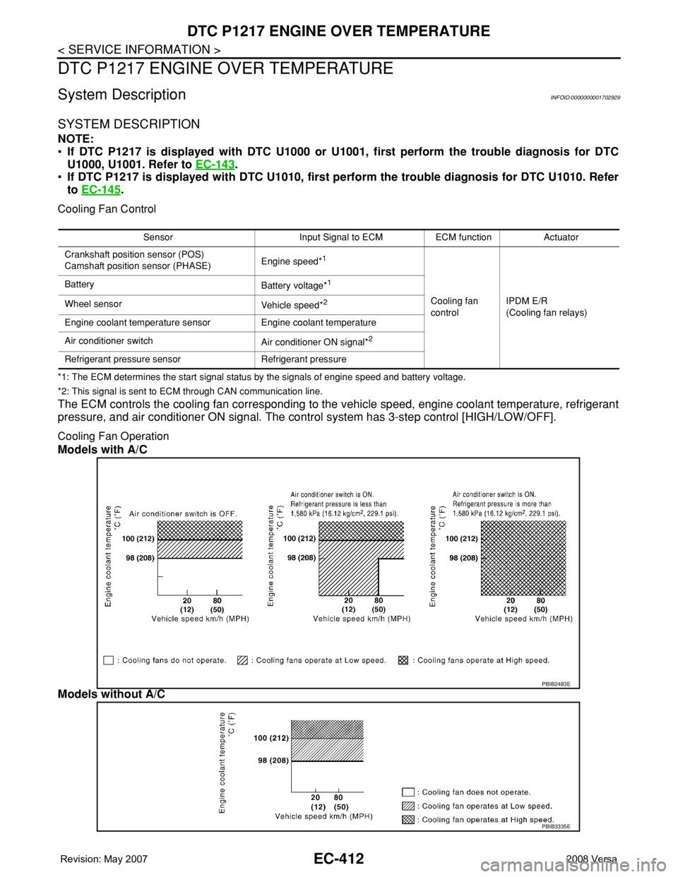
The ECM controls the cooling fan corresponding to the vehicle speed, engine coolant temperature, refrigerant
pressure, and air conditioner ON signal. The control system has 3-step control [HIGH/LOW/OFF].
Cooling Fan Operation
Models with A/C
Models without A/C
Sensor Input Signal to ECM ECM function Actuator
Crankshaft position sensor (POS)
Camshaft position sensor (PHASE)Engine speed*
1
Cooling fan
controlIPDM E/R
(Cooling fan relays) Battery
Battery voltage*
1
Wheel sensor
Vehicle speed*2
Engine coolant temperature sensor Engine coolant temperature
Air conditioner switch
Air conditioner ON signal*
2
Refrigerant pressure sensor Refrigerant pressure
PBIB2483E
PBIB3335E
Page 1489 of 2771
DTC P1217 ENGINE OVER TEMPERATURE
EC-415
< SERVICE INFORMATION >
C
D
E
F
G
H
I
J
K
L
MA
EC
N
P O
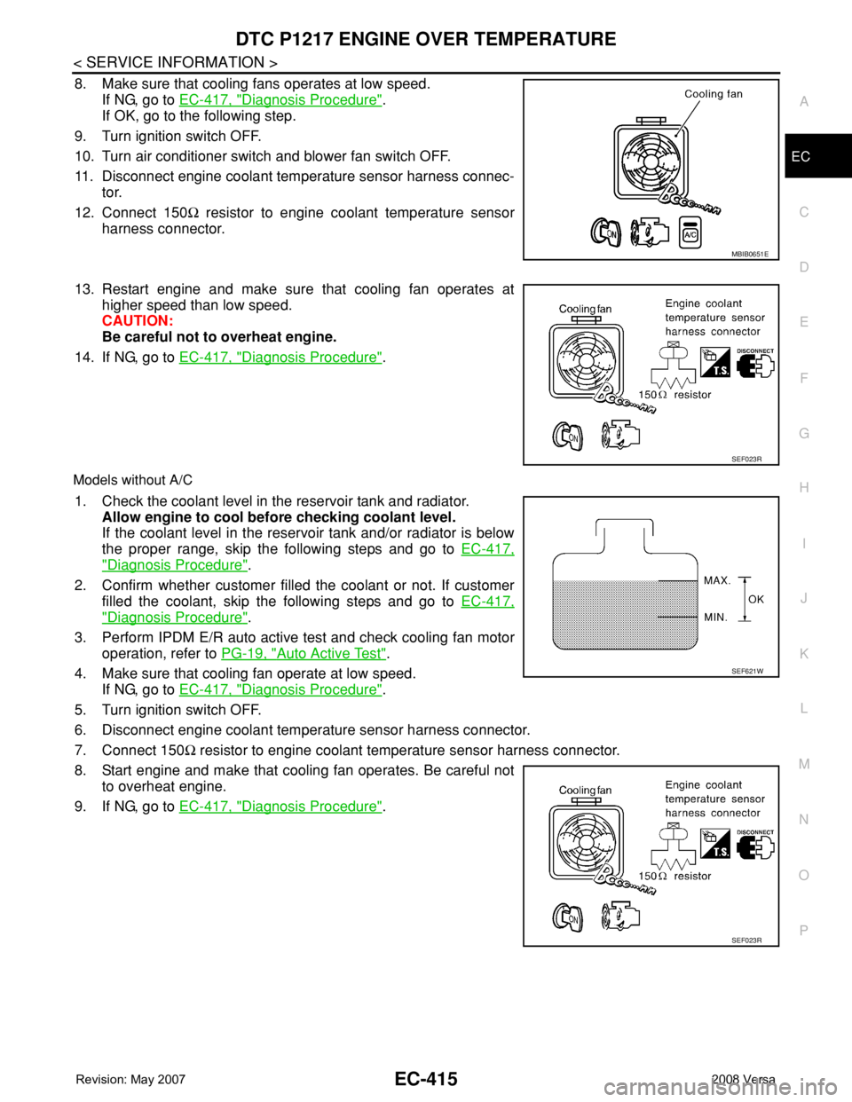
8. Make sure that cooling fans operates at low speed.
If NG, go to EC-417, "
Diagnosis Procedure".
If OK, go to the following step.
9. Turn ignition switch OFF.
10. Turn air conditioner switch and blower fan switch OFF.
11. Disconnect engine coolant temperature sensor harness connec-
tor.
12. Connect 150Ω resistor to engine coolant temperature sensor
harness connector.
13. Restart engine and make sure that cooling fan operates at
higher speed than low speed.
CAUTION:
Be careful not to overheat engine.
14. If NG, go to EC-417, "
Diagnosis Procedure".
Models without A/C
1. Check the coolant level in the reservoir tank and radiator.
Allow engine to cool before checking coolant level.
If the coolant level in the reservoir tank and/or radiator is below
the proper range, skip the following steps and go to EC-417,
"Diagnosis Procedure".
2. Confirm whether customer filled the coolant or not. If customer
filled the coolant, skip the following steps and go to EC-417,
"Diagnosis Procedure".
3. Perform IPDM E/R auto active test and check cooling fan motor
operation, refer to PG-19, "
Auto Active Test".
4. Make sure that cooling fan operate at low speed.
If NG, go to EC-417, "
Diagnosis Procedure".
5. Turn ignition switch OFF.
6. Disconnect engine coolant temperature sensor harness connector.
7. Connect 150Ω resistor to engine coolant temperature sensor harness connector.
8. Start engine and make that cooling fan operates. Be careful not
to overheat engine.
9. If NG, go to EC-417, "
Diagnosis Procedure".
MBIB0651E
SEF023R
SEF621W
SEF023R
Page 1492 of 2771
EC-418
< SERVICE INFORMATION >
DTC P1217 ENGINE OVER TEMPERATURE
No >> GO TO 4.
2.CHECK COOLING FAN LOW SPEED OPERATION
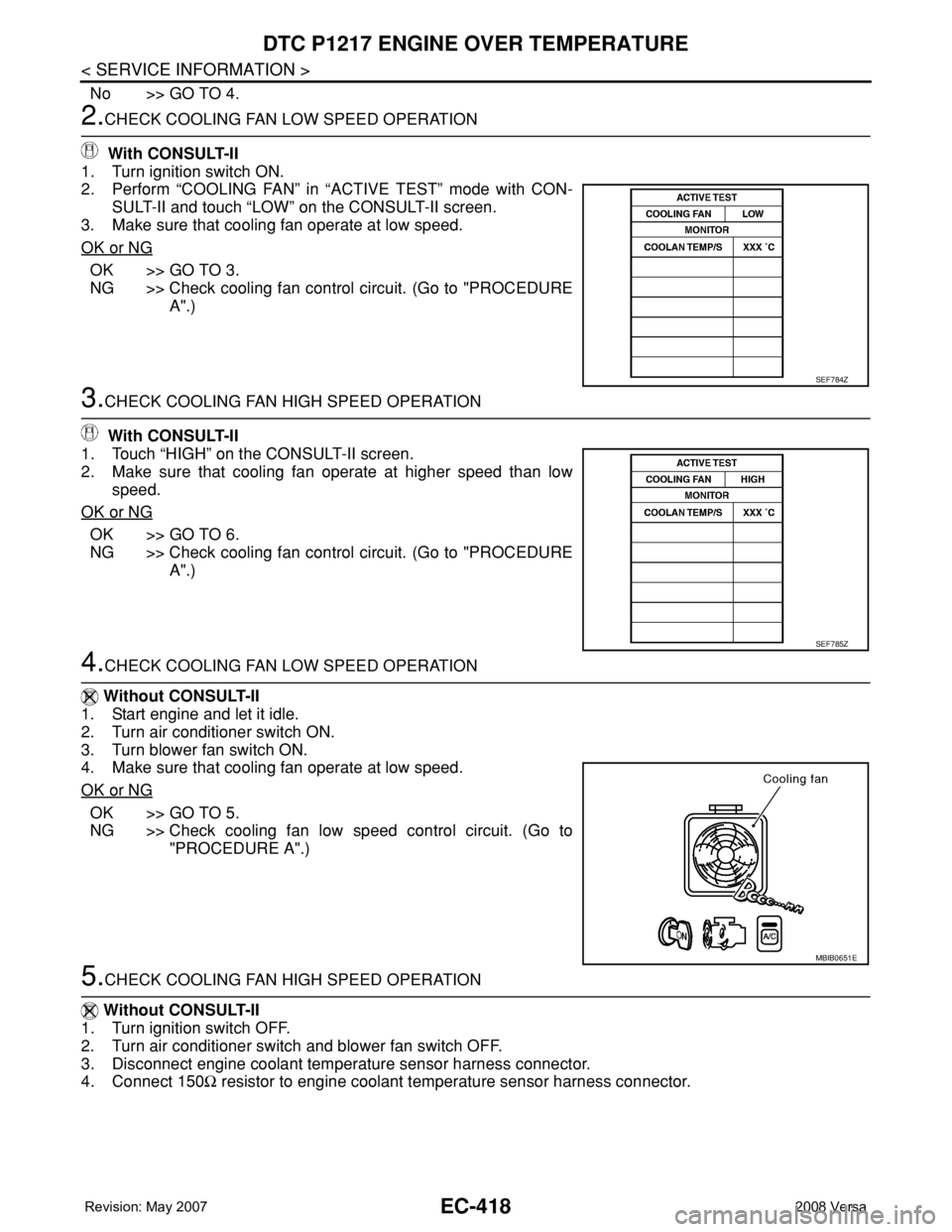
With CONSULT-II
1. Turn ignition switch ON.
2. Perform “COOLING FAN” in “ACTIVE TEST” mode with CON-
SULT-II and touch “LOW” on the CONSULT-II screen.
3. Make sure that cooling fan operate at low speed.
OK or NG
OK >> GO TO 3.
NG >> Check cooling fan control circuit. (Go to "PROCEDURE
A".)
3.CHECK COOLING FAN HIGH SPEED OPERATION
With CONSULT-II
1. Touch “HIGH” on the CONSULT-II screen.
2. Make sure that cooling fan operate at higher speed than low
speed.
OK or NG
OK >> GO TO 6.
NG >> Check cooling fan control circuit. (Go to "PROCEDURE
A".)
4.CHECK COOLING FAN LOW SPEED OPERATION
Without CONSULT-II
1. Start engine and let it idle.
2. Turn air conditioner switch ON.
3. Turn blower fan switch ON.
4. Make sure that cooling fan operate at low speed.
OK or NG
OK >> GO TO 5.
NG >> Check cooling fan low speed control circuit. (Go to
"PROCEDURE A".)
5.CHECK COOLING FAN HIGH SPEED OPERATION
Without CONSULT-II
1. Turn ignition switch OFF.
2. Turn air conditioner switch and blower fan switch OFF.
3. Disconnect engine coolant temperature sensor harness connector.
4. Connect 150Ω resistor to engine coolant temperature sensor harness connector.
SEF784Z
SEF785Z
MBIB0651E
Page 1493 of 2771
DTC P1217 ENGINE OVER TEMPERATURE
EC-419
< SERVICE INFORMATION >
C
D
E
F
G
H
I
J
K
L
MA
EC
N
P O
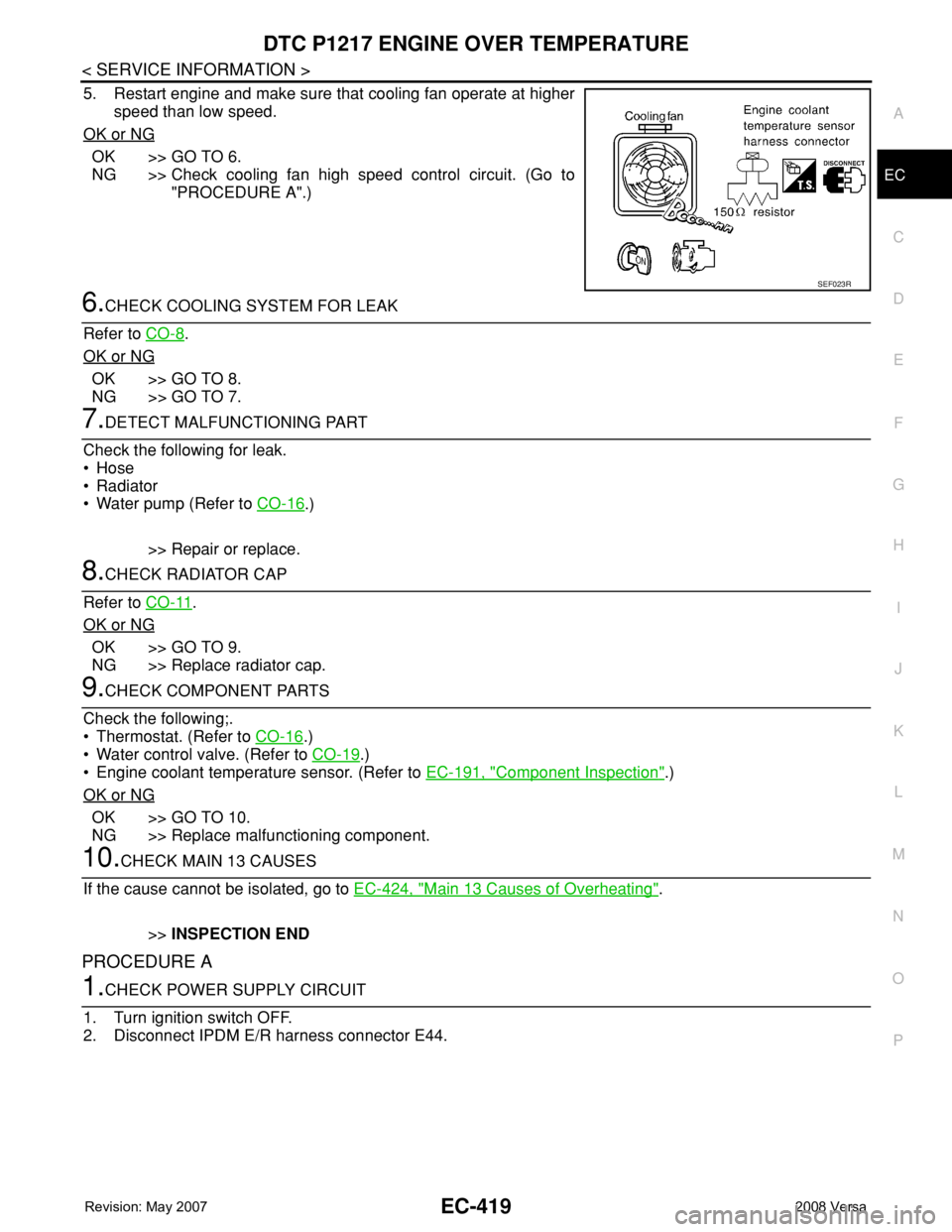
5. Restart engine and make sure that cooling fan operate at higher
speed than low speed.
OK or NG
OK >> GO TO 6.
NG >> Check cooling fan high speed control circuit. (Go to
"PROCEDURE A".)
6.CHECK COOLING SYSTEM FOR LEAK
Refer to CO-8
.
OK or NG
OK >> GO TO 8.
NG >> GO TO 7.
7.DETECT MALFUNCTIONING PART
Check the following for leak.
•Hose
• Radiator
• Water pump (Refer to CO-16
.)
>> Repair or replace.
8.CHECK RADIATOR CAP
Refer to CO-11
.
OK or NG
OK >> GO TO 9.
NG >> Replace radiator cap.
9.CHECK COMPONENT PARTS
Check the following;.
• Thermostat. (Refer to CO-16
.)
• Water control valve. (Refer to CO-19
.)
• Engine coolant temperature sensor. (Refer to EC-191, "
Component Inspection".)
OK or NG
OK >> GO TO 10.
NG >> Replace malfunctioning component.
10.CHECK MAIN 13 CAUSES
If the cause cannot be isolated, go to EC-424, "
Main 13 Causes of Overheating".
>>INSPECTION END
PROCEDURE A
1.CHECK POWER SUPPLY CIRCUIT
1. Turn ignition switch OFF.
2. Disconnect IPDM E/R harness connector E44.
SEF023R
Page 1496 of 2771
EC-422
< SERVICE INFORMATION >
DTC P1217 ENGINE OVER TEMPERATURE
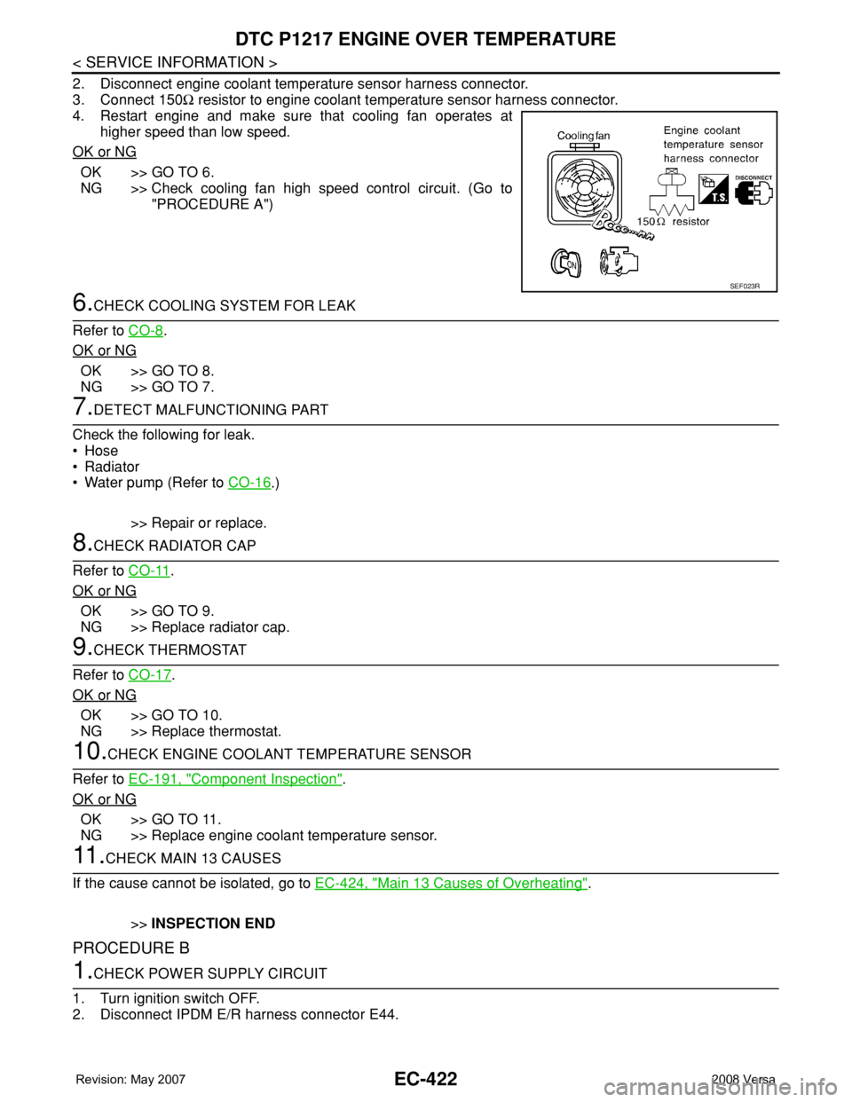
2. Disconnect engine coolant temperature sensor harness connector.
3. Connect 150Ω resistor to engine coolant temperature sensor harness connector.
4. Restart engine and make sure that cooling fan operates at
higher speed than low speed.
OK or NG
OK >> GO TO 6.
NG >> Check cooling fan high speed control circuit. (Go to
"PROCEDURE A")
6.CHECK COOLING SYSTEM FOR LEAK
Refer to CO-8
.
OK or NG
OK >> GO TO 8.
NG >> GO TO 7.
7.DETECT MALFUNCTIONING PART
Check the following for leak.
•Hose
• Radiator
• Water pump (Refer to CO-16
.)
>> Repair or replace.
8.CHECK RADIATOR CAP
Refer to CO-11
.
OK or NG
OK >> GO TO 9.
NG >> Replace radiator cap.
9.CHECK THERMOSTAT
Refer to CO-17
.
OK or NG
OK >> GO TO 10.
NG >> Replace thermostat.
10.CHECK ENGINE COOLANT TEMPERATURE SENSOR
Refer to EC-191, "
Component Inspection".
OK or NG
OK >> GO TO 11.
NG >> Replace engine coolant temperature sensor.
11 .CHECK MAIN 13 CAUSES
If the cause cannot be isolated, go to EC-424, "
Main 13 Causes of Overheating".
>>INSPECTION END
PROCEDURE B
1.CHECK POWER SUPPLY CIRCUIT
1. Turn ignition switch OFF.
2. Disconnect IPDM E/R harness connector E44.
SEF023R
Page 1500 of 2771
EC-426
< SERVICE INFORMATION >
DTC P1225 TP SENSOR
DTC P1225 TP SENSOR
Component DescriptionINFOID:0000000001702937
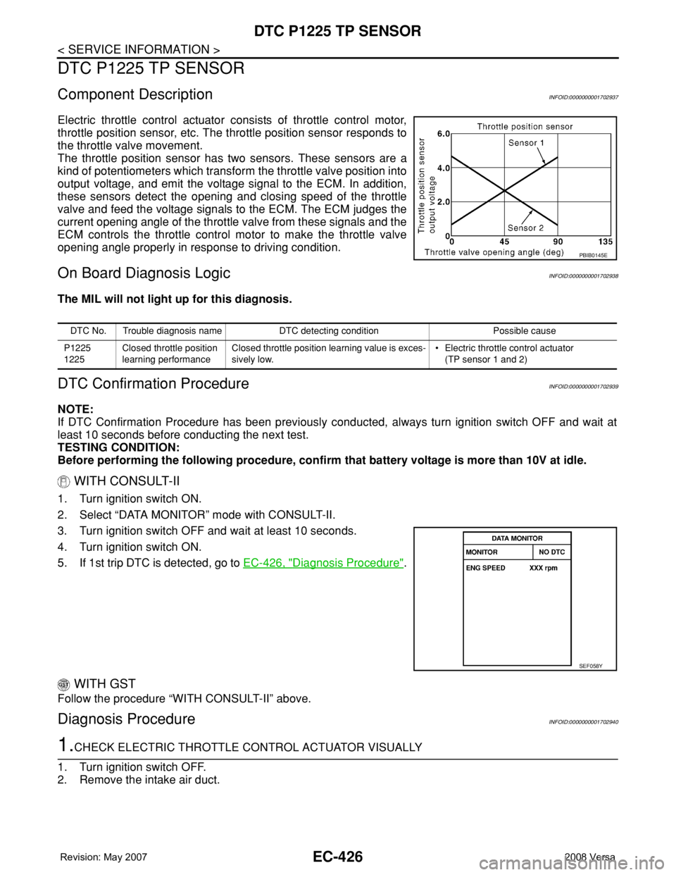
Electric throttle control actuator consists of throttle control motor,
throttle position sensor, etc. The throttle position sensor responds to
the throttle valve movement.
The throttle position sensor has two sensors. These sensors are a
kind of potentiometers which transform the throttle valve position into
output voltage, and emit the voltage signal to the ECM. In addition,
these sensors detect the opening and closing speed of the throttle
valve and feed the voltage signals to the ECM. The ECM judges the
current opening angle of the throttle valve from these signals and the
ECM controls the throttle control motor to make the throttle valve
opening angle properly in response to driving condition.
On Board Diagnosis LogicINFOID:0000000001702938
The MIL will not light up for this diagnosis.
DTC Confirmation ProcedureINFOID:0000000001702939
NOTE:
If DTC Confirmation Procedure has been previously conducted, always turn ignition switch OFF and wait at
least 10 seconds before conducting the next test.
TESTING CONDITION:
Before performing the following procedure, confirm that battery voltage is more than 10V at idle.
WITH CONSULT-II
1. Turn ignition switch ON.
2. Select “DATA MONITOR” mode with CONSULT-II.
3. Turn ignition switch OFF and wait at least 10 seconds.
4. Turn ignition switch ON.
5. If 1st trip DTC is detected, go to EC-426, "
Diagnosis Procedure".
WITH GST
Follow the procedure “WITH CONSULT-II” above.
Diagnosis ProcedureINFOID:0000000001702940
1.CHECK ELECTRIC THROTTLE CONTROL ACTUATOR VISUALLY
1. Turn ignition switch OFF.
2. Remove the intake air duct.
PBIB0145E
DTC No. Trouble diagnosis name DTC detecting condition Possible cause
P1225
1225Closed throttle position
learning performanceClosed throttle position learning value is exces-
sively low.• Electric throttle control actuator
(TP sensor 1 and 2)
SEF058Y
Page 1501 of 2771
DTC P1225 TP SENSOR
EC-427
< SERVICE INFORMATION >
C
D
E
F
G
H
I
J
K
L
MA
EC
N
P O
3. Check if foreign matter is caught between the throttle valve (1)
and the housing.
- : Vehicle front
OK or NG
OK >> GO TO 2.
NG >> Remove the foreign matter and clean the electric throttle
control actuator inside.
2.REPLACE ELECTRIC THROTTLE CONTROL ACTUATOR
1. Replace the electric throttle control actuator.
2. Perform EC-76, "
Throttle Valve Closed Position Learning".
3. Perform EC-76, "
Idle Air Volume Learning".
>>INSPECTION END
Removal and InstallationINFOID:0000000001702941
ELECTRIC THROTTLE CONTROL ACTUATOR
Refer to EM-18.
BBIA0711E
Page 1502 of 2771
EC-428
< SERVICE INFORMATION >
DTC P1226 TP SENSOR
DTC P1226 TP SENSOR
Component DescriptionINFOID:0000000001702942
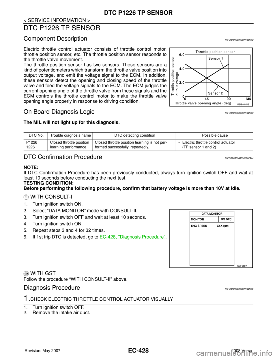
Electric throttle control actuator consists of throttle control motor,
throttle position sensor, etc. The throttle position sensor responds to
the throttle valve movement.
The throttle position sensor has two sensors. These sensors are a
kind of potentiometers which transform the throttle valve position into
output voltage, and emit the voltage signal to the ECM. In addition,
these sensors detect the opening and closing speed of the throttle
valve and feed the voltage signals to the ECM. The ECM judges the
current opening angle of the throttle valve from these signals and the
ECM controls the throttle control motor to make the throttle valve
opening angle properly in response to driving condition.
On Board Diagnosis LogicINFOID:0000000001702943
The MIL will not light up for this diagnosis.
DTC Confirmation ProcedureINFOID:0000000001702944
NOTE:
If DTC Confirmation Procedure has been previously conducted, always turn ignition switch OFF and wait at
least 10 seconds before conducting the next test.
TESTING CONDITION:
Before performing the following procedure, confirm that battery voltage is more than 10V at idle.
WITH CONSULT-II
1. Turn ignition switch ON.
2. Select “DATA MONITOR” mode with CONSULT-II.
3. Turn ignition switch OFF and wait at least 10 seconds.
4. Turn ignition switch ON.
5. Repeat steps 3 and 4 for 32 times.
6. If 1st trip DTC is detected, go to EC-428, "
Diagnosis Procedure".
WITH GST
Follow the procedure “WITH CONSULT-II” above.
Diagnosis ProcedureINFOID:0000000001702945
1.CHECK ELECTRIC THROTTLE CONTROL ACTUATOR VISUALLY
1. Turn ignition switch OFF.
2. Remove the intake air duct.
PBIB0145E
DTC No. Trouble diagnosis name DTC detecting condition Possible cause
P1226
1226Closed throttle position
learning performanceClosed throttle position learning is not per-
formed successfully, repeatedly.• Electric throttle control actuator
(TP sensor 1 and 2)
SEF058Y