2008 NISSAN LATIO parking brake
[x] Cancel search: parking brakePage 2163 of 2771
![NISSAN LATIO 2008 Service Repair Manual LT-26
< SERVICE INFORMATION >
HEADLAMP (FOR CANADA) - DAYTIME LIGHT SYSTEM -
• through 10A fuse [No. 3, located in fuse block (J/B)]
• to combination meter terminal 28.
With the ignition switch in NISSAN LATIO 2008 Service Repair Manual LT-26
< SERVICE INFORMATION >
HEADLAMP (FOR CANADA) - DAYTIME LIGHT SYSTEM -
• through 10A fuse [No. 3, located in fuse block (J/B)]
• to combination meter terminal 28.
With the ignition switch in](/manual-img/5/57360/w960_57360-2162.png)
LT-26
< SERVICE INFORMATION >
HEADLAMP (FOR CANADA) - DAYTIME LIGHT SYSTEM -
• through 10A fuse [No. 3, located in fuse block (J/B)]
• to combination meter terminal 28.
With the ignition switch in the ACC or ON position, power is supplied
• through 10A fuse [No. 20, located in fuse block (J/B)]
• to BCM terminal 11.
Ground is supplied
• to BCM terminal 67 and
• to combination meter terminals 21, 22 and 23
• through grounds M57 and M61,
• to IPDM E/R terminals 39 and 59
• through grounds E15 and E24,
HEADLAMP OPERATION
Low Beam Operation
With the lighting switch in 2ND position, the BCM receives an input signal requesting the headlamps to illumi-
nate. This input signal is communicated to the IPDM E/R via the CAN communication lines. The CPU located
in the IPDM E/R controls the headlamp low relay coil, which when energized, directs power
• through 15A fuse (No. 41, located in IPDM E/R)
• through IPDM E/R terminal 54
• to daytime light relay 2 terminals 1 and 5 (energizing the relay),
• through daytime light relay 2 terminal 3
• to front combination lamp RH terminal 3, and
• through 15A fuse (No. 40, located in IPDM E/R)
• through IPDM E/R terminal 52
• to front combination lamp LH terminal 3.
Ground is supplied
• to front combination lamp LH terminal 2
• through grounds E15 and E24,
• to headlamp RH terminal 2 via
• daytime light relay 1 terminals 3 and 4
• through grounds E15 and E24.
With power and ground supplied, low beam headlamps illuminate.
High Beam/Flash-to-Pass Operation
With the lighting switch in 2ND position and high beam switch in the HIGH position, the BCM receives input
signal requesting the headlamp high beams to illuminate. The flash-to-pass feature can be used any time and
also sends a signal to the BCM. This input signal is communicated to the IPDM E/R and the combination
meter via the CAN communication lines. The CPU located in the IPDM E/R controls the headlamp high relay
coil, which when energized, directs power
• through 10A fuse (No. 34, located in IPDM E/R)
• through IPDM E/R terminal 56
• to front combination lamp RH terminal 1, and
• through 10A fuse (No. 35, located in IPDM E/R)
• through IPDM E/R terminal 55
• to front combination lamp LH terminal 1.
Ground is supplied
• to front combination lamp LH terminal 2
• through grounds E15 and E24, and
• to front combination lamp RH terminal 2 via
• daytime light relay 1 terminals 3 and 4
• through grounds E15 and E24.
With power and ground supplied, the high beam headlamps illuminate.
The BCM sends a signal to the combination meter requesting the high beam indicator lamp to turn ON.
Daytime Light System Operation
With the lighting switch in the OFF or 1ST position (parking lamps ON), the BCM receives inputs requesting
the headlights off. If the parking brake is released and the engine is running, the BCM then sends a signal, via
the CAN communication lines, requesting the IPDM E/R to activate the daytime light system. The CPU located
in the IPDM E/R controls the daytime light relay 1 coil, which when energized, directs power
• from daytime light relay 1 terminal 3
• to front combination lamp RH terminal 2,
• through front combination lamp RH high beam terminal 1
Page 2171 of 2771
LT-34
< SERVICE INFORMATION >
HEADLAMP (FOR CANADA) - DAYTIME LIGHT SYSTEM -
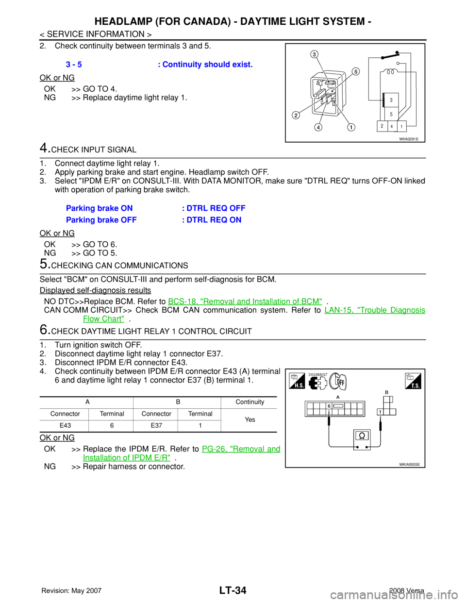
2. Check continuity between terminals 3 and 5.
OK or NG
OK >> GO TO 4.
NG >> Replace daytime light relay 1.
4.CHECK INPUT SIGNAL
1. Connect daytime light relay 1.
2. Apply parking brake and start engine. Headlamp switch OFF.
3. Select "IPDM E/R" on CONSULT-III. With DATA MONITOR, make sure "DTRL REQ" turns OFF-ON linked
with operation of parking brake switch.
OK or NG
OK >> GO TO 6.
NG >> GO TO 5.
5.CHECKING CAN COMMUNICATIONS
Select "BCM" on CONSULT-III and perform self-diagnosis for BCM.
Displayed self-diagnosis results
NO DTC>>Replace BCM. Refer to BCS-18, "Removal and Installation of BCM" .
CAN COMM CIRCUIT>> Check BCM CAN communication system. Refer to LAN-15, "
Trouble Diagnosis
Flow Chart" .
6.CHECK DAYTIME LIGHT RELAY 1 CONTROL CIRCUIT
1. Turn ignition switch OFF.
2. Disconnect daytime light relay 1 connector E37.
3. Disconnect IPDM E/R connector E43.
4. Check continuity between IPDM E/R connector E43 (A) terminal
6 and daytime light relay 1 connector E37 (B) terminal 1.
OK or NG
OK >> Replace the IPDM E/R. Refer to PG-26, "Removal and
Installation of IPDM E/R" .
NG >> Repair harness or connector. 3 - 5 : Continuity should exist.
WIIA0291E
Parking brake ON : DTRL REQ OFF
Parking brake OFF : DTRL REQ ON
ABContinuity
Connector Terminal Connector Terminal
Ye s
E43 6 E37 1
WKIA5553E
Page 2256 of 2771
LU-6
< SERVICE INFORMATION >
ENGINE OIL
ENGINE OIL
InspectionINFOID:0000000001702518
ENGINE OIL LEVEL
NOTE:
Before starting engine, park vehicle on a level surface and check the engine oil level. If engine is already
started, stop it and allow 10 minutes before checking.
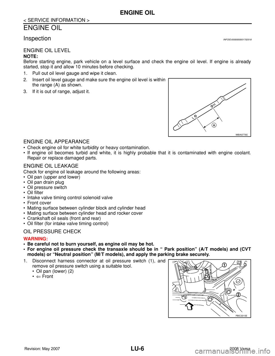
1. Pull out oil level gauge and wipe it clean.
2. Insert oil level gauge and make sure the engine oil level is within
the range (A) as shown.
3. If it is out of range, adjust it.
ENGINE OIL APPEARANCE
• Check engine oil for white turbidity or heavy contamination.
• If engine oil becomes turbid and white, it is highly probable that it is contaminated with engine coolant.
Repair or replace damaged parts.
ENGINE OIL LEAKAGE
Check for engine oil leakage around the following areas:
• Oil pan (upper and lower)
• Oil pan drain plug
• Oil pressure switch
• Oil filter
• Intake valve timing control solenoid valve
• Front cover
• Mating surface between cylinder block and cylinder head
• Mating surface between cylinder head and rocker cover
• Crankshaft oil seals (front and rear)
• Oil filter (for intake valve timing control)
OIL PRESSURE CHECK
WARNING:
• Be careful not to burn yourself, as engine oil may be hot.
• For engine oil pressure check the transaxle should be in “ Park position” (A/T models) and (CVT
models) or “Neutral position” (M/T models), and apply the parking brake securely.
1. Disconnect harness connector at oil pressure switch (1), and
remove oil pressure switch using a suitable tool.
• Oil pan (lower) (2)
•⇐ Front
WBIA0776E
PBIC3310E
Page 2265 of 2771
GENERAL MAINTENANCE
MA-5
< SERVICE INFORMATION >
C
D
E
F
G
H
I
J
K
MA
B
MA
N
O
P
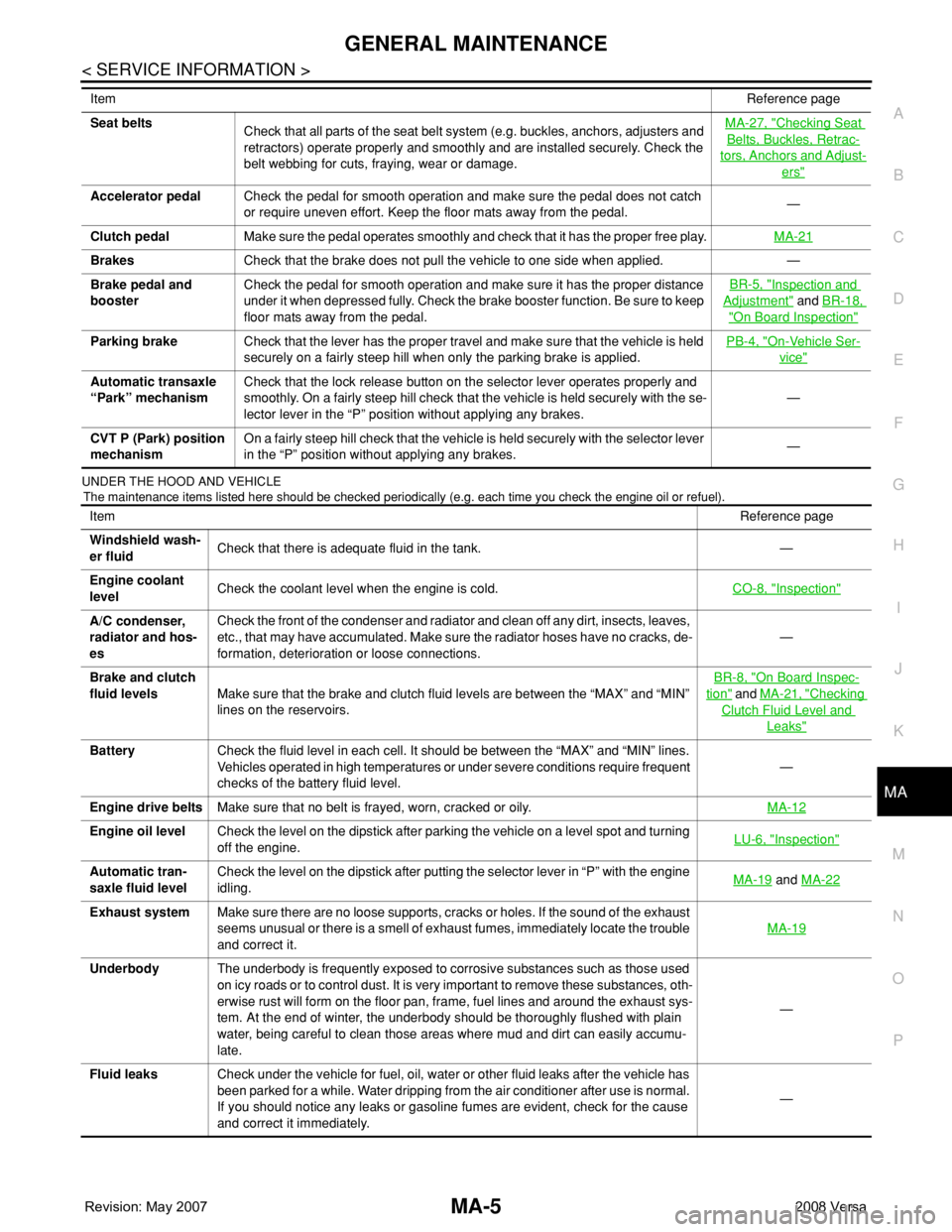
UNDER THE HOOD AND VEHICLE
The maintenance items listed here should be checked periodically (e.g. each time you check the engine oil or refuel).
Seat belts
Check that all parts of the seat belt system (e.g. buckles, anchors, adjusters and
retractors) operate properly and smoothly and are installed securely. Check the
belt webbing for cuts, fraying, wear or damage.MA-27, "Checking Seat
Belts, Buckles, Retrac-
tors, Anchors and Adjust-
ers"
Accelerator pedalCheck the pedal for smooth operation and make sure the pedal does not catch
or require uneven effort. Keep the floor mats away from the pedal.—
Clutch pedalMake sure the pedal operates smoothly and check that it has the proper free play.MA-21
BrakesCheck that the brake does not pull the vehicle to one side when applied. —
Brake pedal and
boosterCheck the pedal for smooth operation and make sure it has the proper distance
under it when depressed fully. Check the brake booster function. Be sure to keep
floor mats away from the pedal.BR-5, "
Inspection and
Adjustment" and BR-18,
"On Board Inspection"
Parking brakeCheck that the lever has the proper travel and make sure that the vehicle is held
securely on a fairly steep hill when only the parking brake is applied.PB-4, "On-Vehicle Ser-
vice"
Automatic transaxle
“Park” mechanismCheck that the lock release button on the selector lever operates properly and
smoothly. On a fairly steep hill check that the vehicle is held securely with the se-
lector lever in the “P” position without applying any brakes.—
CVT P (Park) position
mechanismOn a fairly steep hill check that the vehicle is held securely with the selector lever
in the “P” position without applying any brakes.— ItemReference page
ItemReference page
Windshield wash-
er fluidCheck that there is adequate fluid in the tank. —
Engine coolant
levelCheck the coolant level when the engine is cold.CO-8, "
Inspection"
A/C condenser,
radiator and hos-
esCheck the front of the condenser and radiator and clean off any dirt, insects, leaves,
etc., that may have accumulated. Make sure the radiator hoses have no cracks, de-
formation, deterioration or loose connections.—
Brake and clutch
fluid levelsMake sure that the brake and clutch fluid levels are between the “MAX” and “MIN”
lines on the reservoirs.BR-8, "
On Board Inspec-
tion" and MA-21, "Checking
Clutch Fluid Level and
Leaks"
BatteryCheck the fluid level in each cell. It should be between the “MAX” and “MIN” lines.
Vehicles operated in high temperatures or under severe conditions require frequent
checks of the battery fluid level.—
Engine drive beltsMake sure that no belt is frayed, worn, cracked or oily.MA-12
Engine oil levelCheck the level on the dipstick after parking the vehicle on a level spot and turning
off the engine.LU-6, "Inspection"
Automatic tran-
saxle fluid levelCheck the level on the dipstick after putting the selector lever in “P” with the engine
idling.MA-19 and MA-22
Exhaust systemMake sure there are no loose supports, cracks or holes. If the sound of the exhaust
seems unusual or there is a smell of exhaust fumes, immediately locate the trouble
and correct it.MA-19
UnderbodyThe underbody is frequently exposed to corrosive substances such as those used
on icy roads or to control dust. It is very important to remove these substances, oth-
erwise rust will form on the floor pan, frame, fuel lines and around the exhaust sys-
tem. At the end of winter, the underbody should be thoroughly flushed with plain
water, being careful to clean those areas where mud and dirt can easily accumu-
late.—
Fluid leaksCheck under the vehicle for fuel, oil, water or other fluid leaks after the vehicle has
been parked for a while. Water dripping from the air conditioner after use is normal.
If you should notice any leaks or gasoline fumes are evident, check for the cause
and correct it immediately.—
Page 2279 of 2771
CHASSIS AND BODY MAINTENANCE
MA-19
< SERVICE INFORMATION >
C
D
E
F
G
H
I
J
K
MA
B
MA
N
O
P
CHASSIS AND BODY MAINTENANCE
Changing In-cabin MicrofilterINFOID:0000000001704739
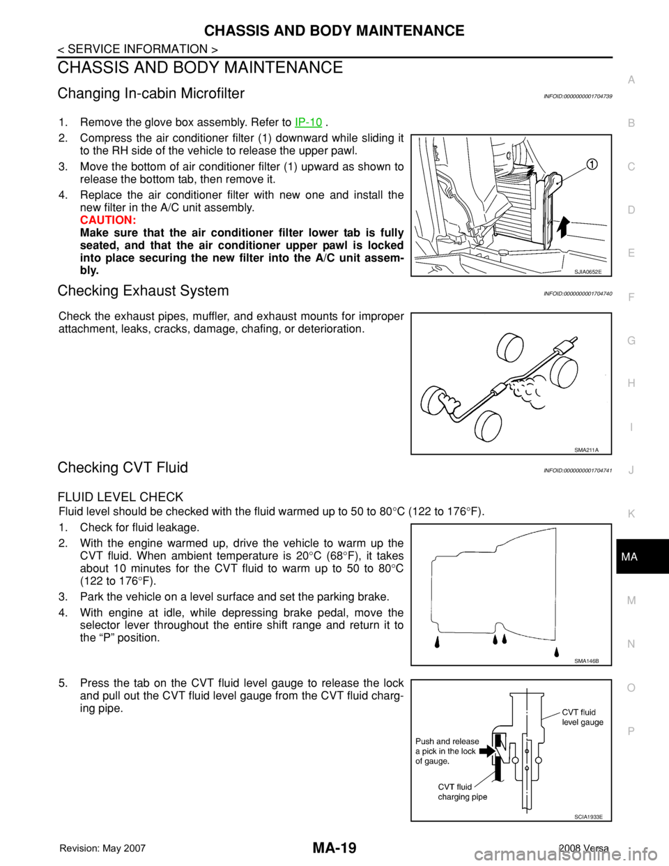
1. Remove the glove box assembly. Refer to IP-10 .
2. Compress the air conditioner filter (1) downward while sliding it
to the RH side of the vehicle to release the upper pawl.
3. Move the bottom of air conditioner filter (1) upward as shown to
release the bottom tab, then remove it.
4. Replace the air conditioner filter with new one and install the
new filter in the A/C unit assembly.
CAUTION:
Make sure that the air conditioner filter lower tab is fully
seated, and that the air conditioner upper pawl is locked
into place securing the new filter into the A/C unit assem-
bly.
Checking Exhaust SystemINFOID:0000000001704740
Check the exhaust pipes, muffler, and exhaust mounts for improper
attachment, leaks, cracks, damage, chafing, or deterioration.
Checking CVT FluidINFOID:0000000001704741
FLUID LEVEL CHECK
Fluid level should be checked with the fluid warmed up to 50 to 80°C (122 to 176°F).
1. Check for fluid leakage.
2. With the engine warmed up, drive the vehicle to warm up the
CVT fluid. When ambient temperature is 20°C (68°F), it takes
about 10 minutes for the CVT fluid to warm up to 50 to 80°C
(122 to 176°F).
3. Park the vehicle on a level surface and set the parking brake.
4. With engine at idle, while depressing brake pedal, move the
selector lever throughout the entire shift range and return it to
the “P” position.
5. Press the tab on the CVT fluid level gauge to release the lock
and pull out the CVT fluid level gauge from the CVT fluid charg-
ing pipe.
SJIA0652E
SMA211A
SMA146B
SCIA1933E
Page 2282 of 2771
MA-22
< SERVICE INFORMATION >
CHASSIS AND BODY MAINTENANCE
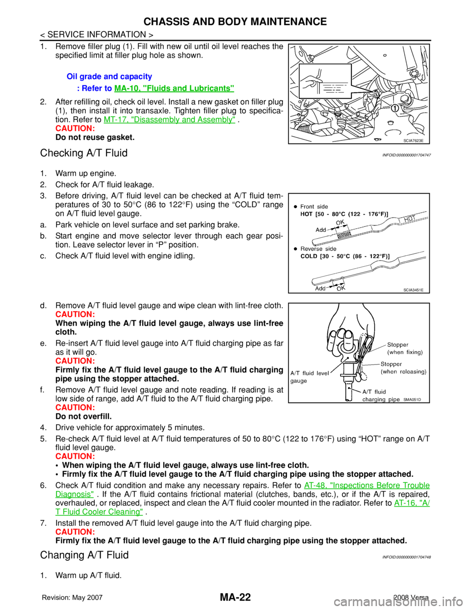
1. Remove filler plug (1). Fill with new oil until oil level reaches the
specified limit at filler plug hole as shown.
2. After refilling oil, check oil level. Install a new gasket on filler plug
(1), then install it into transaxle. Tighten filler plug to specifica-
tion. Refer to MT-17, "
Disassembly and Assembly" .
CAUTION:
Do not reuse gasket.
Checking A/T FluidINFOID:0000000001704747
1. Warm up engine.
2. Check for A/T fluid leakage.
3. Before driving, A/T fluid level can be checked at A/T fluid tem-
peratures of 30 to 50°C (86 to 122°F) using the “COLD” range
on A/T fluid level gauge.
a. Park vehicle on level surface and set parking brake.
b. Start engine and move selector lever through each gear posi-
tion. Leave selector lever in “P” position.
c. Check A/T fluid level with engine idling.
d. Remove A/T fluid level gauge and wipe clean with lint-free cloth.
CAUTION:
When wiping the A/T fluid level gauge, always use lint-free
cloth.
e. Re-insert A/T fluid level gauge into A/T fluid charging pipe as far
as it will go.
CAUTION:
Firmly fix the A/T fluid level gauge to the A/T fluid charging
pipe using the stopper attached.
f. Remove A/T fluid level gauge and note reading. If reading is at
low side of range, add A/T fluid to the A/T fluid charging pipe.
CAUTION:
Do not overfill.
4. Drive vehicle for approximately 5 minutes.
5. Re-check A/T fluid level at A/T fluid temperatures of 50 to 80°C (122 to 176°F) using “HOT” range on A/T
fluid level gauge.
CAUTION:
• When wiping the A/T fluid level gauge, always use lint-free cloth.
• Firmly fix the A/T fluid level gauge to the A/T fluid charging pipe using the stopper attached.
6. Check A/T fluid condition and make any necessary repairs. Refer to AT-48, "
Inspections Before Trouble
Diagnosis" . If the A/T fluid contains frictional material (clutches, bands, etc.), or if the A/T is repaired,
overhauled, or replaced, inspect and clean the A/T fluid cooler mounted in the radiator. Refer to AT-16, "
A/
T Fluid Cooler Cleaning" .
7. Install the removed A/T fluid level gauge into the A/T fluid charging pipe.
CAUTION:
Firmly fix the A/T fluid level gauge to the A/T fluid charging pipe using the stopper attached.
Changing A/T FluidINFOID:0000000001704748
1. Warm up A/T fluid.Oil grade and capacity
: Refer to MA-10, "
Fluids and Lubricants"
SCIA7623E
SCIA3451E
SMA051D
Page 2284 of 2771
MA-24
< SERVICE INFORMATION >
CHASSIS AND BODY MAINTENANCE
Checking Brake Line and Cables
INFOID:0000000001704752
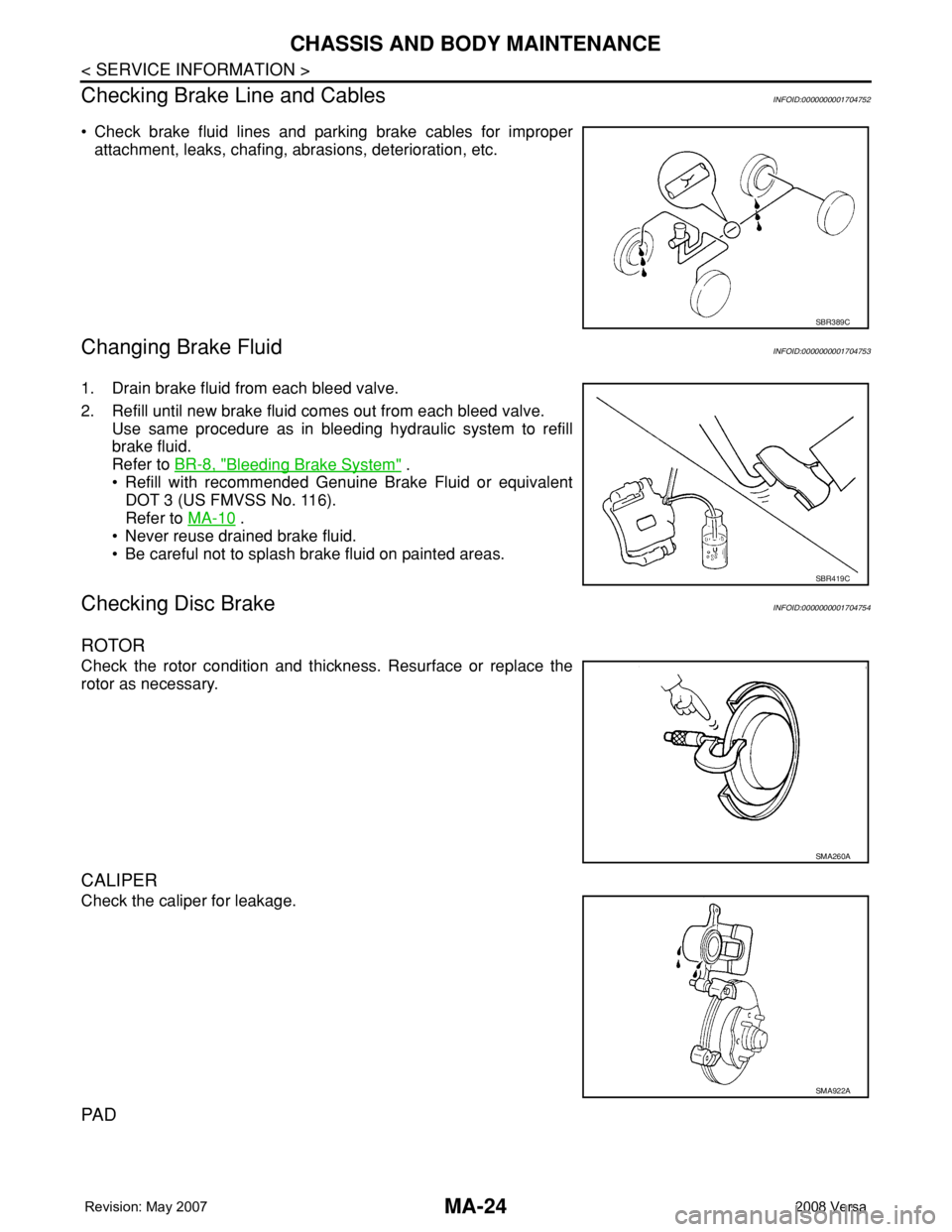
• Check brake fluid lines and parking brake cables for improper
attachment, leaks, chafing, abrasions, deterioration, etc.
Changing Brake FluidINFOID:0000000001704753
1. Drain brake fluid from each bleed valve.
2. Refill until new brake fluid comes out from each bleed valve.
Use same procedure as in bleeding hydraulic system to refill
brake fluid.
Refer to BR-8, "
Bleeding Brake System" .
• Refill with recommended Genuine Brake Fluid or equivalent
DOT 3 (US FMVSS No. 116).
Refer to MA-10
.
• Never reuse drained brake fluid.
• Be careful not to splash brake fluid on painted areas.
Checking Disc BrakeINFOID:0000000001704754
ROTOR
Check the rotor condition and thickness. Resurface or replace the
rotor as necessary.
CALIPER
Check the caliper for leakage.
PA D
SBR389C
SBR419C
SMA260A
SMA922A
Page 2427 of 2771

PB-1
BRAKES
C
D
E
G
H
I
J
K
L
M
SECTION PB
A
B
PB
N
O
P
CONTENTS
PARKING BRAKE SYSTEM
SERVICE INFORMATION ............................2
PRECAUTIONS ...................................................2
Precaution for Supplemental Restraint System
(SRS) "AIR BAG" and "SEAT BELT PRE-TEN-
SIONER" ...................................................................
2
PREPARATION ...................................................3
Commercial Service Tool ..........................................3
PARKING BRAKE CONTROL ...........................4
On-Vehicle Service ...................................................4
Component ...............................................................5
Removal and Installation ..........................................5
SERVICE DATA AND SPECIFICATIONS
(SDS) ..................................................................
7
Parking Brake Control ..............................................7