2008 NISSAN LATIO parking brake
[x] Cancel search: parking brakePage 1068 of 2771
WARNING CHIME
DI-47
< SERVICE INFORMATION >
C
D
E
F
G
H
I
J
L
MA
B
DI
N
O
P
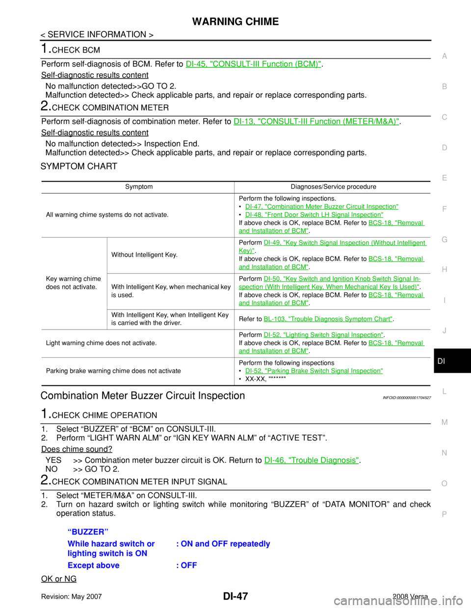
1.CHECK BCM
Perform self-diagnosis of BCM. Refer to DI-45, "
CONSULT-III Function (BCM)".
Self
-diagnostic results content
No malfunction detected>>GO TO 2.
Malfunction detected>> Check applicable parts, and repair or replace corresponding parts.
2.CHECK COMBINATION METER
Perform self-diagnosis of combination meter. Refer to DI-13, "
CONSULT-III Function (METER/M&A)".
Self
-diagnostic results content
No malfunction detected>> Inspection End.
Malfunction detected>> Check applicable parts, and repair or replace corresponding parts.
SYMPTOM CHART
Combination Meter Buzzer Circuit InspectionINFOID:0000000001704527
1.CHECK CHIME OPERATION
1. Select “BUZZER” of “BCM” on CONSULT-III.
2. Perform “LIGHT WARN ALM” or “IGN KEY WARN ALM” of “ACTIVE TEST”.
Does chime sound?
YES >> Combination meter buzzer circuit is OK. Return to DI-46, "Trouble Diagnosis".
NO >> GO TO 2.
2.CHECK COMBINATION METER INPUT SIGNAL
1. Select “METER/M&A” on CONSULT-III.
2. Turn on hazard switch or lighting switch while monitoring “BUZZER” of “DATA MONITOR” and check
operation status.
OK or NG
Symptom Diagnoses/Service procedure
All warning chime systems do not activate.Perform the following inspections.
•DI-47, "
Combination Meter Buzzer Circuit Inspection"
•DI-48, "Front Door Switch LH Signal Inspection"
If above check is OK, replace BCM. Refer to BCS-18, "Removal
and Installation of BCM".
Key warning chime
does not activate.Without Intelligent Key.Perform DI-49, "
Key Switch Signal Inspection (Without Intelligent
Key)".
If above check is OK, replace BCM. Refer to BCS-18, "
Removal
and Installation of BCM".
With Intelligent Key, when mechanical key
is used.Perform DI-50, "
Key Switch and Ignition Knob Switch Signal In-
spection (With Intelligent Key, When Mechanical Key Is Used)".
If above check is OK, replace BCM. Refer to BCS-18, "
Removal
and Installation of BCM".
With Intelligent Key, when Intelligent Key
is carried with the driver.Refer to BL-103, "
Trouble Diagnosis Symptom Chart".
Light warning chime does not activate.Perform DI-52, "
Lighting Switch Signal Inspection".
If above check is OK, replace BCM. Refer to BCS-18, "
Removal
and Installation of BCM".
Parking brake warning chime does not activatePerform the following inspections
•DI-52, "
Parking Brake Switch Signal Inspection"
• XX-XX, "*****"
“BUZZER”
While hazard switch or
lighting switch is ON : ON and OFF repeatedly
Except above : OFF
Page 1073 of 2771
DI-52
< SERVICE INFORMATION >
WARNING CHIME
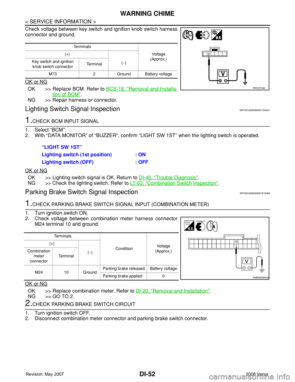
Check voltage between key switch and ignition knob switch harness
connector and ground.
OK or NG
OK >> Replace BCM. Refer to BCS-18, "Removal and Installa-
tion of BCM".
NG >> Repair harness or connector.
Lighting Switch Signal InspectionINFOID:0000000001704531
1.CHECK BCM INPUT SIGNAL
1. Select “BCM”.
2. With “DATA MONITOR” of “BUZZER”, confirm “LIGHT SW 1ST” when the lighting switch is operated.
OK or NG
OK >> Lighting switch signal is OK. Return to DI-46, "Trouble Diagnosis".
NG >> Check the lighting switch. Refer to LT-63, "
Combination Switch Inspection".
Parking Brake Switch Signal InspectionINFOID:0000000001815489
1.CHECK PARKING BRAKE SWITCH SIGNAL INPUT (COMBINATION METER)
1. Turn ignition switch ON.
2. Check voltage between combination meter harness connector
M24 terminal 10 and ground.
OK or NG
OK >> Replace combination meter. Refer to DI-20, "Removal and Installation".
NG >> GO TO 2.
2.CHECK PARKING BRAKE SWITCH CIRCUIT
1. Turn ignition switch OFF.
2. Disconnect combination meter connector and parking brake switch connector.
Te r m i n a l s
Vo l ta g e
(Approx.) (+)
(−) Key switch and ignition
knob switch connector Te r m i n a l
M73 2 Ground Battery voltage
PKIC0724E
“LIGHT SW 1ST”
Lighting switch (1st position) : ON
Lighting switch (OFF) : OFF
Te r m i n a l s
ConditionVoltag e
(Approx.) (+)
(−) Combination
meter
connectorTe r m i n a l
M24 10 GroundParking brake released Battery voltage
Parking brake applied 0
AWMIA0066GB
Page 1074 of 2771
WARNING CHIME
DI-53
< SERVICE INFORMATION >
C
D
E
F
G
H
I
J
L
MA
B
DI
N
O
P
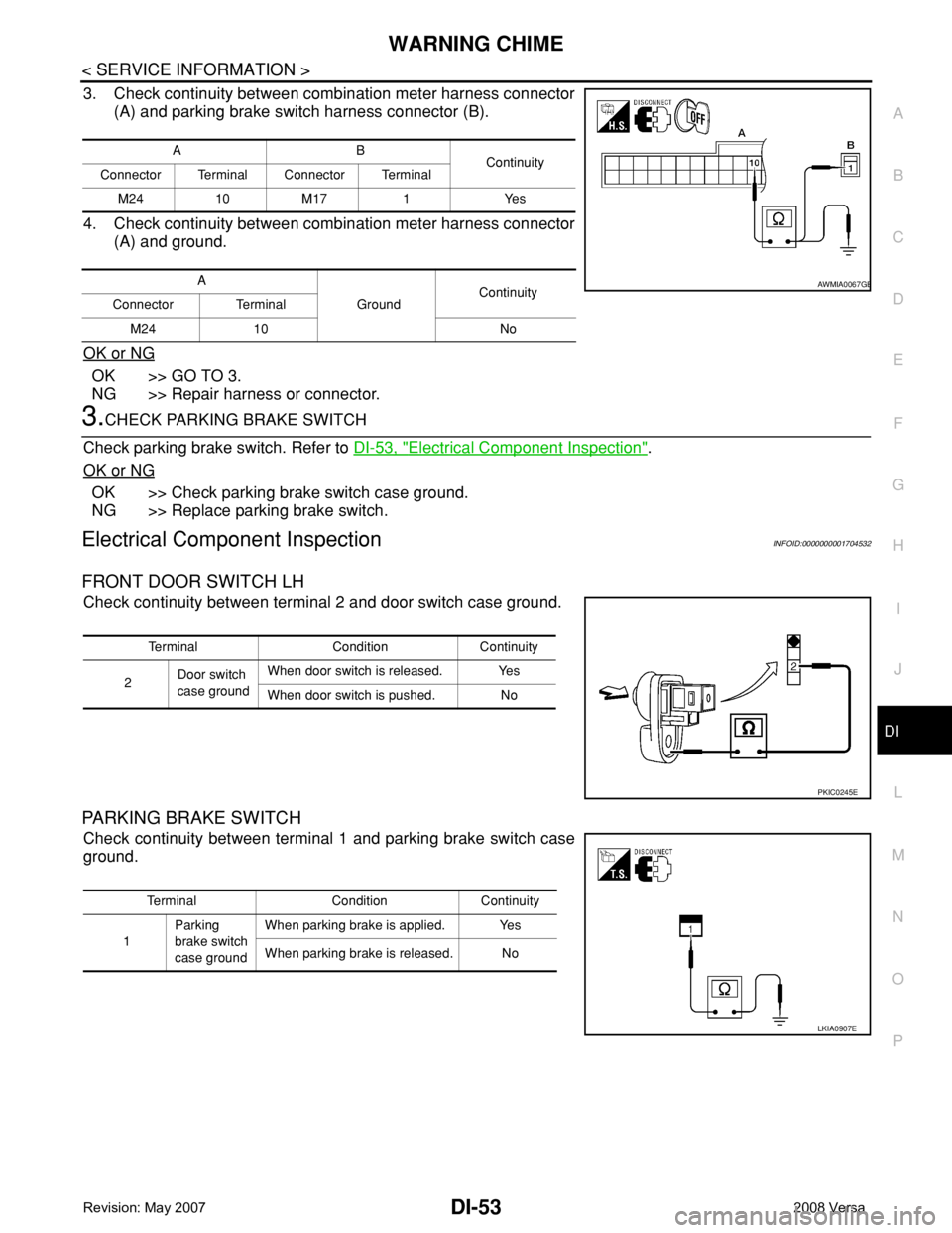
3. Check continuity between combination meter harness connector
(A) and parking brake switch harness connector (B).
4. Check continuity between combination meter harness connector
(A) and ground.
OK or NG
OK >> GO TO 3.
NG >> Repair harness or connector.
3.CHECK PARKING BRAKE SWITCH
Check parking brake switch. Refer to DI-53, "
Electrical Component Inspection".
OK or NG
OK >> Check parking brake switch case ground.
NG >> Replace parking brake switch.
Electrical Component InspectionINFOID:0000000001704532
FRONT DOOR SWITCH LH
Check continuity between terminal 2 and door switch case ground.
PARKING BRAKE SWITCH
Check continuity between terminal 1 and parking brake switch case
ground.
AB
Continuity
Connector Terminal Connector Terminal
M2410M17 1 Yes
A
GroundContinuity
Connector Terminal
M24 10 No
AWMIA0067GB
Terminal Condition Continuity
2Door switch
case groundWhen door switch is released. Yes
When door switch is pushed. No
PKIC0245E
Terminal Condition Continuity
1Parking
brake switch
case groundWhen parking brake is applied. Yes
When parking brake is released. No
LKIA0907E
Page 1150 of 2771

EC-76
< SERVICE INFORMATION >
BASIC SERVICE PROCEDURE
Accelerator Pedal Released Position Learning
INFOID:0000000001702582
DESCRIPTION
Accelerator Pedal Released Position Learning is an operation to learn the fully released position of the accel-
erator pedal by monitoring the accelerator pedal position sensor output signal. It must be performed each time
harness connector of accelerator pedal position sensor or ECM is disconnected.
OPERATION PROCEDURE
1. Make sure that accelerator pedal is fully released.
2. Turn ignition switch ON and wait at least 2 seconds.
3. Turn ignition switch OFF and wait at least 10 seconds.
4. Turn ignition switch ON and wait at least 2 seconds.
5. Turn ignition switch OFF and wait at least 10 seconds.
Throttle Valve Closed Position LearningINFOID:0000000001702583
DESCRIPTION
Throttle Valve Closed Position Learning is an operation to learn the fully closed position of the throttle valve by
monitoring the throttle position sensor output signal. It must be performed each time harness connector of
electric throttle control actuator or ECM is disconnected.
OPERATION PROCEDURE
1. Make sure that accelerator pedal is fully released.
2. Turn ignition switch ON.
3. Turn ignition switch OFF and wait at least 10 seconds.
Make sure that throttle valve moves during above 10 seconds by confirming the operating sound.
Idle Air Volume LearningINFOID:0000000001702584
DESCRIPTION
Idle Air Volume Learning is an operation to learn the idle air volume that keeps each engine within the specific
range. It must be performed under any of the following conditions:
• Each time electric throttle control actuator or ECM is replaced.
• Idle speed or ignition timing is out of specification.
PREPARATION
Before performing Idle Air Volume Learning, make sure that all of the following conditions are satisfied.
Learning will be cancelled if any of the following conditions are missed for even a moment.
• Battery voltage: More than 12.9V (At idle)
• Engine coolant temperature: 70 - 95°C (158 - 203°F)
• Park/neutral position (PNP) switch: ON
• Electric load switch: OFF
[Air conditioner, headlamp, rear window defogger]
On vehicles equipped with daytime light systems, if the parking brake is applied before the engine is
started the headlamp will not be illuminated.
• Steering wheel: Neutral (Straight-ahead position)
• Vehicle speed: Stopped
• Transmission: Warmed-up
- Models with CONSULT-II (A/T and CVT models)
• Drive vehicle until “FLUID TEMP SE” in “DATA MONITOR” mode of “A/T” or “CVT” system indicates less
than 0.9V.
- Models without CONSULT-II (A/T and CVT models) and M/T models
• Drive vehicle for 10 minutes.
OPERATION PROCEDURE
With CONSULT-II
1. Perform EC-76, "Accelerator Pedal Released Position Learning".
2. Perform EC-76, "
Throttle Valve Closed Position Learning".
Page 1830 of 2771
FL-10
< SERVICE INFORMATION >
FUEL TANK
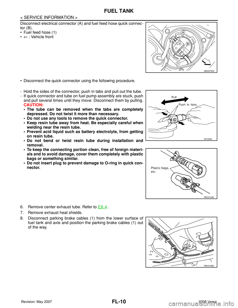
Disconnect electrical connector (A) and fuel feed hose quick connec-
tor (B).
• Fuel feed hose (1)
•⇐ : Vehicle front
• Disconnect the quick connector using the following procedure.
- Hold the sides of the connector, push in tabs and pull out the tube.
- If quick connector and tube on fuel pump assembly are stuck, push
and pull several times until they move. Disconnect them by pulling.
CAUTION:
• The tube can be removed when the tabs are completely
depressed. Do not twist it more than necessary.
• Do not use any tools to remove the quick connector.
• Keep resin tube away from heat. Be especially careful when
welding near the resin tube.
• Prevent acid liquid such as battery electrolyte, from getting
on resin tube.
• Do not bend or twist resin tube during installation and
removal.
• To keep the connecting portion clean, free of foreign materi-
als and to avoid damage, cover them completely with plastic
bags or something similar.
• Do not insert plug to prevent damage to O-ring in quick con-
nector.
6. Remove center exhaust tube. Refer to EX-4
.
7. Remove exhaust heat shields.
8. Disconnect parking brake cables (1) from the lower surface of
fuel tank and axle and position the parking brake cables (1) out
of the way.
WBIA0782E
SFE562A
PBIC0163E
PBIC3786E
Page 1869 of 2771
GI-18
< SERVICE INFORMATION >
HOW TO USE THIS MANUAL
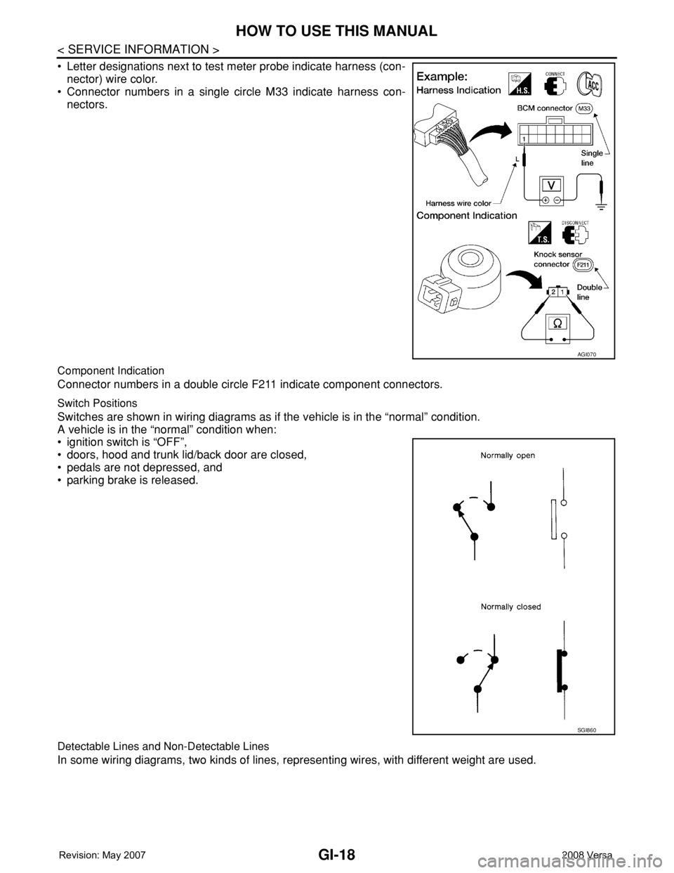
• Letter designations next to test meter probe indicate harness (con-
nector) wire color.
• Connector numbers in a single circle M33 indicate harness con-
nectors.
Component Indication
Connector numbers in a double circle F211 indicate component connectors.
Switch Positions
Switches are shown in wiring diagrams as if the vehicle is in the “normal” condition.
A vehicle is in the “normal” condition when:
• ignition switch is “OFF”,
• doors, hood and trunk lid/back door are closed,
• pedals are not depressed, and
• parking brake is released.
Detectable Lines and Non-Detectable Lines
In some wiring diagrams, two kinds of lines, representing wires, with different weight are used.
AGI070
SGI860
Page 2149 of 2771

LT-12
< SERVICE INFORMATION >
HEADLAMP (FOR USA)
Note 1: Vehicles without daytime light system may display this item, but cannot monitor it.
ACTIVE TEST
Display Item List
SELF-DIAGNOSTIC RESULTS
Display Item List
CONSULT-III Function (IPDM E/R)INFOID:0000000001704370
CONSULT-III can display each diagnostic item using the diagnostic test modes shown following.
DATA MONITOR
All Items, Main Items, Select Item Menu
LIGHT SW 1ST "ON/OFF"Displays status (lighting switch 1st position: ON/Others: OFF) of lighting switch judged from lighting
switch signal.
PASSING SW "ON/OFF"Displays status (flash-to-pass switch: ON/Others: OFF) of flash-to-pass switch judged from lighting
switch signal.
FR FOG SW "ON/OFF"Displays status (front fog lamp switch: ON/Others: OFF) of front fog lamp switch judged from light-
ing switch signal.
DOOR SW - DR "ON/OFF"Displays status of the front door LH as judged from the front door switch LH signal. (Door is open:
ON/Door is closed: OFF)
DOOR SW - AS "ON/OFF"Displays status of the front door RH as judged from the front door switch RH signal. (Door is open:
ON/Door is closed: OFF)
DOOR SW - RR "ON/OFF"Displays status of the rear door as judged from the rear door switch (RH) signal. (Door is open:
ON/Door is closed: OFF)
DOOR SW - RL "ON/OFF"Displays status of the rear door as judged from the rear door switch (LH) signal. (Door is open: ON/
Door is closed: OFF)
BACK DOOR SW "ON/OFF"Displays status of the back door as judged from the back door switch signal. (Door is open: ON/
Door is closed: OFF)
TURN SIGNAL R "ON/OFF" Displays status (Turn right: ON/Others: OFF) as judged from lighting switch signal.
TURN SIGNAL L "ON/OFF" Displays status (Turn left: ON/Others: OFF) as judged from lighting switch signal.
ENGINE RUN
Note 1"ON/OFF" Displays status (Engine running: ON/Others: OFF) as judged from engine status signal.
PKB SW
Note 1"ON/OFF"Displays status (Parking brake switch: ON/Others: OFF) as judged from parking brake switch sig-
nal. Monitor item Contents
Test item Description
TAIL LAMP Allows tail lamp relay to operate by switching ON-OFF.
HEAD LAMP Allows headlamp relay (HI, LO) to operate by switching ON-OFF.
FR FOG LAMP Allows fog lamp relay to operate by switching ON-OFF.
Monitored item CONSULT-llI display Description
CAN communication CAN communication [U1000] Malfunction is detected in CAN communication.
CAN communication system CAN communication system 1 to 6 [U1000] Malfunction is detected in CAN system.
IPDM E/R diagnostic Mode Description
SELF-DIAG RESULTS Displays IPDM E/R self-diagnosis results.
DATA MONITOR Displays IPDM E/R input/output data in real time.
CAN DIAG SUPPORT MNTR The result of transmit/receive diagnosis of CAN communication can be read.
ACTIVE TEST Operation of electrical loads can be checked by sending drive signal to them.
Page 2162 of 2771
HEADLAMP (FOR CANADA) - DAYTIME LIGHT SYSTEM -
LT-25
< SERVICE INFORMATION >
C
D
E
F
G
H
I
J
L
MA
B
LT
N
O
P
HEADLAMP (FOR CANADA) - DAYTIME LIGHT SYSTEM -
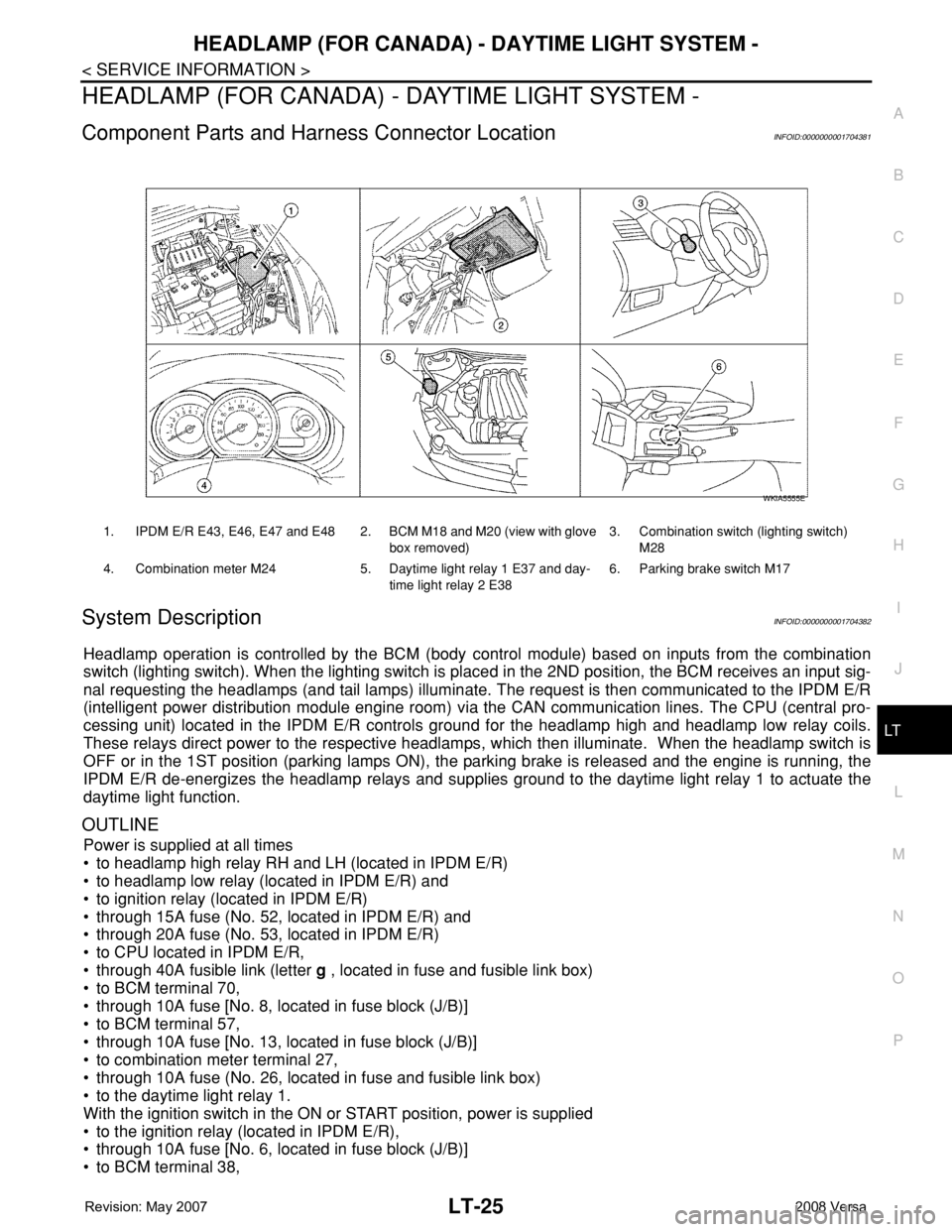
Component Parts and Harness Connector LocationINFOID:0000000001704381
System DescriptionINFOID:0000000001704382
Headlamp operation is controlled by the BCM (body control module) based on inputs from the combination
switch (lighting switch). When the lighting switch is placed in the 2ND position, the BCM receives an input sig-
nal requesting the headlamps (and tail lamps) illuminate. The request is then communicated to the IPDM E/R
(intelligent power distribution module engine room) via the CAN communication lines. The CPU (central pro-
cessing unit) located in the IPDM E/R controls ground for the headlamp high and headlamp low relay coils.
These relays direct power to the respective headlamps, which then illuminate. When the headlamp switch is
OFF or in the 1ST position (parking lamps ON), the parking brake is released and the engine is running, the
IPDM E/R de-energizes the headlamp relays and supplies ground to the daytime light relay 1 to actuate the
daytime light function.
OUTLINE
Power is supplied at all times
• to headlamp high relay RH and LH (located in IPDM E/R)
• to headlamp low relay (located in IPDM E/R) and
• to ignition relay (located in IPDM E/R)
• through 15A fuse (No. 52, located in IPDM E/R) and
• through 20A fuse (No. 53, located in IPDM E/R)
• to CPU located in IPDM E/R,
• through 40A fusible link (letter g , located in fuse and fusible link box)
• to BCM terminal 70,
• through 10A fuse [No. 8, located in fuse block (J/B)]
• to BCM terminal 57,
• through 10A fuse [No. 13, located in fuse block (J/B)]
• to combination meter terminal 27,
• through 10A fuse (No. 26, located in fuse and fusible link box)
• to the daytime light relay 1.
With the ignition switch in the ON or START position, power is supplied
• to the ignition relay (located in IPDM E/R),
• through 10A fuse [No. 6, located in fuse block (J/B)]
• to BCM terminal 38,
1. IPDM E/R E43, E46, E47 and E48 2. BCM M18 and M20 (view with glove
box removed)3. Combination switch (lighting switch)
M28
4. Combination meter M24 5. Daytime light relay 1 E37 and day-
time light relay 2 E386. Parking brake switch M17
WKIA5555E