2008 NISSAN LATIO transmission fluid
[x] Cancel search: transmission fluidPage 954 of 2771

DTC P0845 TRANSMISSION FLUID PRESSURE SENSOR B CIRCUIT (PRI
PRESSURE SENSOR)
CVT-115
< SERVICE INFORMATION >
D
E
F
G
H
I
J
K
L
MA
B
CVT
N
O
P
DTC P0845 TRANSMISSION FLUID PRESSURE SENSOR B CIRCUIT (PRI
PRESSURE SENSOR)
DescriptionINFOID:0000000001703586
• The transmission fluid pressure sensor B (primary pressure sensor) is included in the control valve assem-
bly.
• The transmission fluid pressure sensor B (primary pressure sensor) detects primary pressure of CVT and
sends TCM the signal.
CONSULT-III Reference Value in Data Monitor ModeINFOID:0000000001703587
Remarks: Specification data are reference values.
On Board Diagnosis LogicINFOID:0000000001703588
• This is an OBD-II self-diagnostic item.
• Diagnostic trouble code “P0845 TR PRS SENS/B CIRC” with CONSULT-III is detected under the following
conditions.
- When TCM detects an improper voltage drop when it receives the sensor signal.
- When TCM compares target value with monitor value and detects an irregularity.
Possible CauseINFOID:0000000001703589
• Transmission fluid pressure sensor B (Primary pressure sensor)
• Harness or connectors
(Sensor circuit is open or shorted.)
DTC Confirmation ProcedureINFOID:0000000001703590
NOTE:
If “DTC Confirmation Procedure” has been previously performed, always turn ignition switch OFF and
wait at least 10 seconds before performing the next test.
After the repair, perform the following procedure to confirm the malfunction is eliminated.
WITH CONSULT-III
1. Turn ignition switch ON and select “DATA MONITOR” mode for “TRANSMISSION” with CONSULT-III.
2. Make sure that output voltage of line temperature sensor is within the range below.
ATF TEMP SEN: 1.0 - 2.0 V
If out of range, drive the vehicle to decrease the voltage (warm up the fluid) or stop engine to
increase the voltage (cool down the fluid)
3. Start engine and wait for at least 5 consecutive seconds.
4. If DTC is detected, go to CVT-117, "
Diagnosis Procedure" .
WITH GST
Follow the procedure “WITH CONSULT-III”.
Item name Condition Display value (Approx.)
PRI HYDR SEN “N” position idle 0.7 V
Page 955 of 2771
CVT-116
< SERVICE INFORMATION >
DTC P0845 TRANSMISSION FLUID PRESSURE SENSOR B CIRCUIT (PRI
PRESSURE SENSOR)
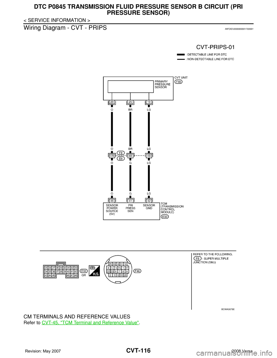
Wiring Diagram - CVT - PRIPS
INFOID:0000000001703591
CM TERMINALS AND REFERENCE VALUES
Refer to CVT-45, "TCM Terminal and Reference Value".
BCWA0678E
Page 956 of 2771
DTC P0845 TRANSMISSION FLUID PRESSURE SENSOR B CIRCUIT (PRI
PRESSURE SENSOR)
CVT-117
< SERVICE INFORMATION >
D
E
F
G
H
I
J
K
L
MA
B
CVT
N
O
P
Diagnosis ProcedureINFOID:0000000001703592
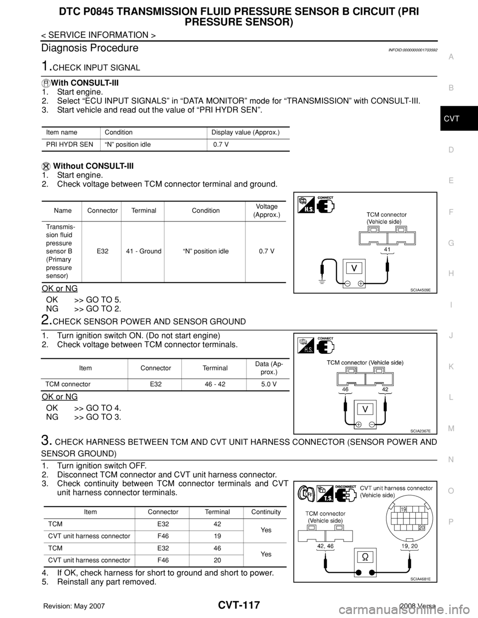
1.CHECK INPUT SIGNAL
With CONSULT-III
1. Start engine.
2. Select “ECU INPUT SIGNALS” in “DATA MONITOR” mode for “TRANSMISSION” with CONSULT-III.
3. Start vehicle and read out the value of “PRI HYDR SEN”.
Without CONSULT-III
1. Start engine.
2. Check voltage between TCM connector terminal and ground.
OK or NG
OK >> GO TO 5.
NG >> GO TO 2.
2.CHECK SENSOR POWER AND SENSOR GROUND
1. Turn ignition switch ON. (Do not start engine)
2. Check voltage between TCM connector terminals.
OK or NG
OK >> GO TO 4.
NG >> GO TO 3.
3. CHECK HARNESS BETWEEN TCM AND CVT UNIT HARNESS CONNECTOR (SENSOR POWER AND
SENSOR GROUND)
1. Turn ignition switch OFF.
2. Disconnect TCM connector and CVT unit harness connector.
3. Check continuity between TCM connector terminals and CVT
unit harness connector terminals.
4. If OK, check harness for short to ground and short to power.
5. Reinstall any part removed.
Item name Condition Display value (Approx.)
PRI HYDR SEN “N” position idle 0.7 V
Name Connector Terminal ConditionVoltage
(Approx.)
Transmis-
sion fluid
pressure
sensor B
(Primary
pressure
sensor)E32 41 - Ground “N” position idle 0.7 V
SCIA4509E
Item Connector TerminalData (Ap-
prox.)
TCM connector E32 46 - 42 5.0 V
SCIA2367E
Item Connector Terminal Continuity
TCM E32 42
Ye s
CVT unit harness connector F46 19
TCM E32 46
Ye s
CVT unit harness connector F46 20
SCIA4681E
Page 957 of 2771
CVT-118
< SERVICE INFORMATION >
DTC P0845 TRANSMISSION FLUID PRESSURE SENSOR B CIRCUIT (PRI
PRESSURE SENSOR)
OK or NG
OK >> Replace TCM. Refer to CVT-8, "Service After Replacing TCM and Transaxle Assembly" .
NG >> Repair open circuit or short to ground or short to power in harness or connectors.
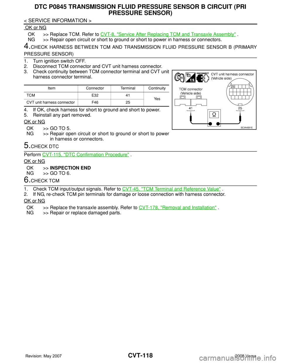
4.CHECK HARNESS BETWEEN TCM AND TRANSMISSION FLUID PRESSURE SENSOR B (PRIMARY
PRESSURE SENSOR)
1. Turn ignition switch OFF.
2. Disconnect TCM connector and CVT unit harness connector.
3. Check continuity between TCM connector terminal and CVT unit
harness connector terminal.
4. If OK, check harness for short to ground and short to power.
5. Reinstall any part removed.
OK or NG
OK >> GO TO 5.
NG >> Repair open circuit or short to ground or short to power
in harness or connectors.
5.CHECK DTC
Perform CVT-115, "
DTC Confirmation Procedure" .
OK or NG
OK >>INSPECTION END
NG >> GO TO 6.
6.CHECK TCM
1. Check TCM input/output signals. Refer to CVT-45, "
TCM Terminal and Reference Value" .
2. If NG, re-check TCM pin terminals for damage or loose connection with harness connector.
OK or NG
OK >> Replace the transaxle assembly. Refer to CVT-178, "Removal and Installation" .
NG >> Repair or replace damaged parts.
Item Connector Terminal Continuity
TCM E32 41
Ye s
CVT unit harness connector F46 25
SCIA4691E
Page 958 of 2771
DTC P0868 SECONDARY PRESSURE DOWN
CVT-119
< SERVICE INFORMATION >
D
E
F
G
H
I
J
K
L
MA
B
CVT
N
O
P
DTC P0868 SECONDARY PRESSURE DOWN
DescriptionINFOID:0000000001703593
• The pressure control solenoid valve B (secondary pressure solenoid valve) is included in the control valve
assembly.
• The pressure control solenoid valve B (secondary pressure solenoid valve) regulates the secondary pres-
sure to suit the driving condition in response to a signal sent from the TCM.
CONSULT-III Reference Value in Data Monitor ModeINFOID:0000000001703594
Remarks: Specification data are reference values.
On Board Diagnosis LogicINFOID:0000000001703595
• This is not an OBD-II self-diagnostic item.
• Diagnostic trouble code “P0868 SEC/PRESS DOWN” with CONSULT-III is detected when secondary fluid
pressure is too low compared with the commanded value while driving.
Possible CauseINFOID:0000000001703596
• Harness or connectors
(Solenoid circuit is open or shorted.)
• Pressure control solenoid valve B (Secondary pressure solenoid valve) system
• Transmission fluid pressure sensor A (Secondary pressure sensor)
• Line pressure control system
DTC Confirmation ProcedureINFOID:0000000001703597
CAUTION:
Always drive vehicle at a safe speed.
NOTE:
If “DTC Confirmation Procedure” has been previously performed, always turn ignition switch OFF and
wait at least 10 seconds before performing the next test.
After the repair, perform the following procedure to confirm the malfunction is eliminated.
WITH CONSULT-III
1. Turn ignition switch ON and select “DATA MONITOR” mode for “TRANSMISSION” with CONSULT-III.
2. Make sure that output voltage of CVT fluid temperature sensor is within the range below.
ATF TEMP SEN: 1.0 - 2.0 V
If out of range, drive the vehicle to decrease the voltage (warm up the fluid) or stop engine to
increase the voltage (cool down the fluid)
3. Start engine and maintain the following conditions for at least 10 consecutive seconds.
VEHICLE SPEED (accelerate slowly): 0 → 50 km/h (31 MPH)
ACC PEDAL OPEN: 0.5/8 - 1.0/8
RANGE: “D” position
4. If DTC is detected, go to CVT-119, "
Diagnosis Procedure".
Diagnosis ProcedureINFOID:0000000001703598
1.CHECK INPUT SIGNAL
With CONSULT-III
1. Start engine.
2. Select “MAIN SIGNALS” in “DATA MONITOR” mode for “TRANSMISSION” with CONSULT-III.
3. Start vehicle and read out the value of “SEC PRESS”.
Item name Condition Display value (Approx.)
SEC PRESS “N” position idle 0.8 MPa
Item name Condition Display value (Approx.)
SEC PRESS “N” position idle 0.8 MPa
Page 959 of 2771
CVT-120
< SERVICE INFORMATION >
DTC P0868 SECONDARY PRESSURE DOWN
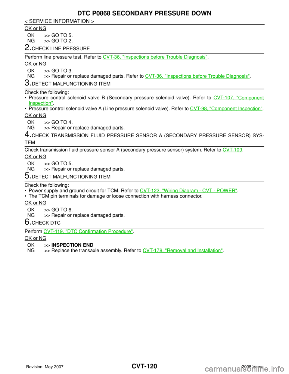
OK or NG
OK >> GO TO 5.
NG >> GO TO 2.
2.CHECK LINE PRESSURE
Perform line pressure test. Refer to CVT-36, "
Inspections before Trouble Diagnosis".
OK or NG
OK >> GO TO 3.
NG >> Repair or replace damaged parts. Refer to CVT-36, "
Inspections before Trouble Diagnosis".
3.DETECT MALFUNCTIONING ITEM
Check the following:
• Pressure control solenoid valve B (Secondary pressure solenoid valve). Refer to CVT-107, "
Component
Inspection".
• Pressure control solenoid valve A (Line pressure solenoid valve). Refer to CVT-98, "
Component Inspection".
OK or NG
OK >> GO TO 4.
NG >> Repair or replace damaged parts.
4.CHECK TRANSMISSION FLUID PRESSURE SENSOR A (SECONDARY PRESSURE SENSOR) SYS-
TEM
Check transmission fluid pressure sensor A (secondary pressure sensor) system. Refer to CVT-109
.
OK or NG
OK >> GO TO 5.
NG >> Repair or replace damaged parts.
5.DETECT MALFUNCTIONING ITEM
Check the following:
• Power supply and ground circuit for TCM. Refer to CVT-122, "
Wiring Diagram - CVT - POWER".
• The TCM pin terminals for damage or loose connection with harness connector.
OK or NG
OK >> GO TO 6.
NG >> Repair or replace damaged parts.
6.CHECK DTC
Perform CVT-119, "
DTC Confirmation Procedure".
OK or NG
OK >>INSPECTION END
NG >> Replace the transaxle assembly. Refer to CVT-178, "
Removal and Installation".
Page 975 of 2771
CVT-136
< SERVICE INFORMATION >
DTC P1745 LINE PRESSURE CONTROL
DTC P1745 LINE PRESSURE CONTROL
DescriptionINFOID:0000000001703635
The pressure control solenoid valve A (line pressure solenoid valve) regulates the oil pump discharge pres-
sure to suit the driving condition in response to a signal sent from the TCM.
On Board Diagnosis LogicINFOID:0000000001703636
• This is not an OBD-II self-diagnostic item.
• Diagnostic trouble code “P1745 L/PRESS CONTROL” with CONSULT-III is detected when TCM detects the
unexpected line pressure.
Possible CauseINFOID:0000000001703637
TCM
DTC Confirmation ProcedureINFOID:0000000001703638
NOTE:
If “DTC Confirmation Procedure” has been previously performed, always turn ignition switch OFF and
wait at least 10 seconds before performing the next test.
After the repair, touch “ERASE” on “SELF-DIAG RESULTS” and then perform the following procedure to con-
firm the malfunction is eliminated.
WITH CONSULT-III
1. Turn ignition switch ON and select “DATA MONITOR” mode for “TRANSMISSION” with CONSULT-III.
2. Make sure that output voltage of CVT fluid temperature sensor is within the range below.
ATF TEMP SEN: 1.0 - 2.0 V
If out of range, drive the vehicle to decrease the voltage (warm up the fluid) or stop engine to
increase the voltage (cool down the fluid)
3. If DTC is detected, go to CVT-136, "
Diagnosis Procedure" .
Diagnosis ProcedureINFOID:0000000001703639
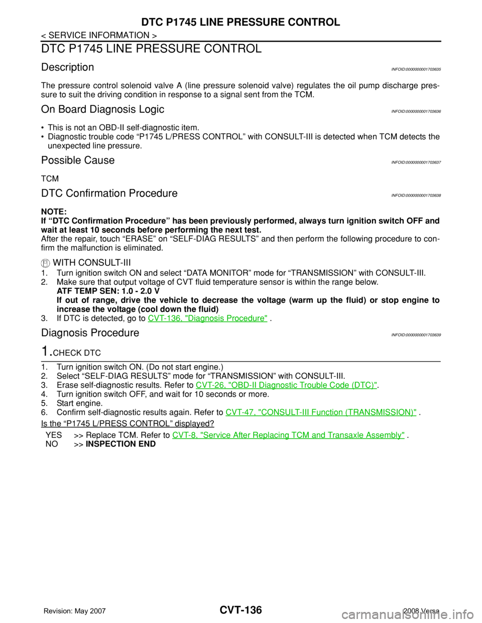
1.CHECK DTC
1. Turn ignition switch ON. (Do not start engine.)
2. Select “SELF-DIAG RESULTS” mode for “TRANSMISSION” with CONSULT-III.
3. Erase self-diagnostic results. Refer to CVT-26, "
OBD-II Diagnostic Trouble Code (DTC)".
4. Turn ignition switch OFF, and wait for 10 seconds or more.
5. Start engine.
6. Confirm self-diagnostic results again. Refer to CVT-47, "
CONSULT-III Function (TRANSMISSION)" .
Is the
“P1745 L/PRESS CONTROL” displayed?
YES >> Replace TCM. Refer to CVT-8, "Service After Replacing TCM and Transaxle Assembly" .
NO >>INSPECTION END
Page 980 of 2771
DTC P1778 STEP MOTOR - FUNCTION
CVT-141
< SERVICE INFORMATION >
D
E
F
G
H
I
J
K
L
MA
B
CVT
N
O
P
DTC P1778 STEP MOTOR - FUNCTION
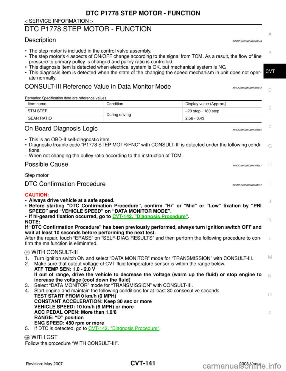
DescriptionINFOID:0000000001703648
• The step motor is included in the control valve assembly.
• The step motor's 4 aspects of ON/OFF change according to the signal from TCM. As a result, the flow of line
pressure to primary pulley is changed and pulley ratio is controlled.
• This diagnosis item is detected when electrical system is OK, but mechanical system is NG.
• This diagnosis item is detected when the state of the changing the speed mechanism in unit does not oper-
ate normally.
CONSULT-III Reference Value in Data Monitor ModeINFOID:0000000001703649
Remarks: Specification data are reference values.
On Board Diagnosis LogicINFOID:0000000001703650
• This is an OBD-II self-diagnostic item.
• Diagnostic trouble code “P1778 STEP MOTR/FNC” with CONSULT-III is detected under the following condi-
tions.
- When not changing the pulley ratio according to the instruction of TCM.
Possible CauseINFOID:0000000001703651
Step motor
DTC Confirmation ProcedureINFOID:0000000001703652
CAUTION:
• Always drive vehicle at a safe speed.
• Before starting “DTC Confirmation Procedure”, confirm “Hi” or “Mid” or “Low” fixation by “PRI
SPEED” and “VEHICLE SPEED” on “DATA MONITOR MODE”.
• If hi-geared fixation occurred, go to CVT-142, "
Diagnosis Procedure".
NOTE:
If “DTC Confirmation Procedure” has been previously performed, always turn ignition switch OFF and
wait at least 10 seconds before performing the next test.
After the repair, touch “ERASE” on “SELF-DIAG RESULTS” and then perform the following procedure to con-
firm the malfunction is eliminated.
WITH CONSULT-III
1. Turn ignition switch ON and select “DATA MONITOR” mode for “TRANSMISSION” with CONSULT-III.
2. Make sure that output voltage of CVT fluid temperature sensor is within the range below.
ATF TEMP SEN: 1.0 - 2.0 V
If out of range, drive the vehicle to decrease the voltage (warm up the fluid) or stop engine to
increase the voltage (cool down the fluid)
3. Select “DATA MONITOR” mode for “TRANSMISSION” with CONSULT-III.
4. Start engine and maintain the following conditions for at least 30 consecutive seconds.
TEST START FROM 0 km/h (0 MPH)
CONSTANT ACCELERATION: Keep 30 sec or more
VEHICLE SPEED: 10 km/h (6 MPH) or more
ACC PEDAL OPEN: More than 1.0/8
RANGE: “D” position
ENG SPEED: 450 rpm or more
5. If DTC is detected, go to CVT-142, "
Diagnosis Procedure".
WITH GST
Follow the procedure “WITH CONSULT-III”.
Item name Condition Display value (Approx.)
STM STEP
During driving−20 step - 180 step
GEAR RATIO2.56 - 0.43