2008 NISSAN LATIO ignition
[x] Cancel search: ignitionPage 1069 of 2771
DI-48
< SERVICE INFORMATION >
WARNING CHIME
OK >> Check battery power supply circuit of combination meter. If OK, replace combination meter. Refer
to IP-11, "
Removal and Installation".
NG >> Replace BCM. Refer to BCS-18, "
Removal and Installation of BCM".
Front Door Switch LH Signal InspectionINFOID:0000000001704528
1.CHECK BCM INPUT SIGNAL
With CONSULT-III
1. Select “BCM”.
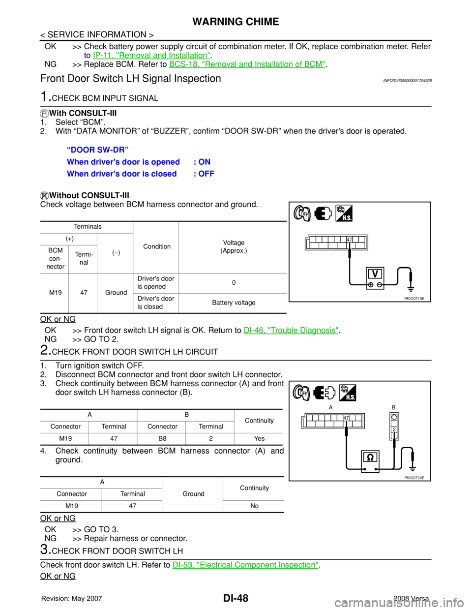
2. With “DATA MONITOR” of “BUZZER”, confirm “DOOR SW-DR” when the driver's door is operated.
Without CONSULT-III
Check voltage between BCM harness connector and ground.
OK or NG
OK >> Front door switch LH signal is OK. Return to DI-46, "Trouble Diagnosis".
NG >> GO TO 2.
2.CHECK FRONT DOOR SWITCH LH CIRCUIT
1. Turn ignition switch OFF.
2. Disconnect BCM connector and front door switch LH connector.
3. Check continuity between BCM harness connector (A) and front
door switch LH harness connector (B).
4. Check continuity between BCM harness connector (A) and
ground.
OK or NG
OK >> GO TO 3.
NG >> Repair harness or connector.
3.CHECK FRONT DOOR SWITCH LH
Check front door switch LH. Refer to DI-53, "
Electrical Component Inspection".
OK or NG
“DOOR SW-DR”
When driver's door is opened : ON
When driver's door is closed : OFF
Te r m i n a l s
ConditionVol tag e
(Approx.) (+)
(−) BCM
con-
nectorTe r m i -
nal
M19 47 GroundDriver's door
is opened0
Driver's door
is closedBattery voltage
PKIC0719E
AB
Continuity
Connector Terminal Connector Terminal
M19 47 B8 2 Yes
A
GroundContinuity
Connector Terminal
M19 47 No
PKIC0720E
Page 1070 of 2771
WARNING CHIME
DI-49
< SERVICE INFORMATION >
C
D
E
F
G
H
I
J
L
MA
B
DI
N
O
P
OK >> Replace BCM. Refer to BCS-18, "Removal and Installation of BCM".
NG >> Replace front door switch LH.
Key Switch Signal Inspection (Without Intelligent Key)INFOID:0000000001704529
1.CHECK FUSE
Check if the key switch and key lock solenoid 10A fuse [No. 14, located in the fuse block (J/B)] is blown.
OK or NG
OK >> GO TO 2.
NG >> Be sure to repair the cause of malfunction before installing new fuse. Refer to PG-3
.
2.CHECK BCM INPUT SIGNAL
With CONSULT-III
1. Select “BCM”.
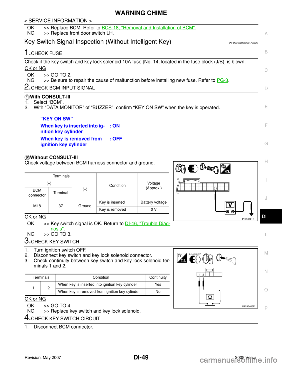
2. With “DATA MONITOR” of “BUZZER”, confirm “KEY ON SW” when the key is operated.
Without CONSULT-III
Check voltage between BCM harness connector and ground.
OK or NG
OK >> Key switch signal is OK. Return to DI-46, "Trouble Diag-
nosis".
NG >> GO TO 3.
3.CHECK KEY SWITCH
1. Turn ignition switch OFF.
2. Disconnect key switch and key lock solenoid connector.
3. Check continuity between key switch and key lock solenoid ter-
minals 1 and 2.
OK or NG
OK >> GO TO 4.
NG >> Replace key switch and key lock solenoid.
4.CHECK KEY SWITCH CIRCUIT
1. Disconnect BCM connector.“KEY ON SW”
When key is inserted into ig-
nition key cylinder: ON
When key is removed from
ignition key cylinder: OFF
Te r m i n a l s
ConditionVoltag e
(Approx.) (+)
(−)
BCM
connectorTe r m i n a l
M18 37 GroundKey is inserted Battery voltage
Key is removed 0 V
PKIC0721E
Terminals Condition Continuity
12When key is inserted into ignition key cylinder Yes
When key is removed from ignition key cylinder No
WKIA5466E
Page 1071 of 2771
DI-50
< SERVICE INFORMATION >
WARNING CHIME
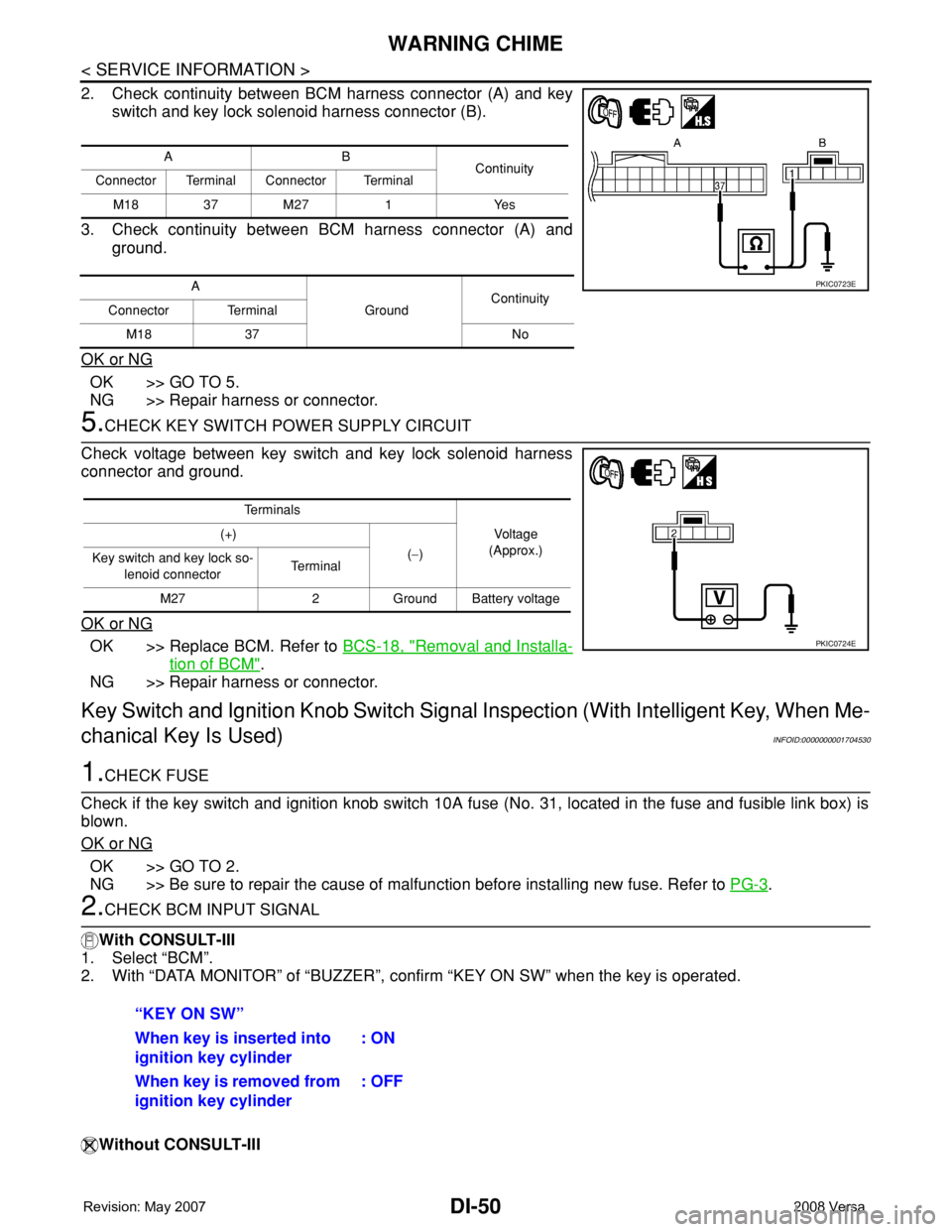
2. Check continuity between BCM harness connector (A) and key
switch and key lock solenoid harness connector (B).
3. Check continuity between BCM harness connector (A) and
ground.
OK or NG
OK >> GO TO 5.
NG >> Repair harness or connector.
5.CHECK KEY SWITCH POWER SUPPLY CIRCUIT
Check voltage between key switch and key lock solenoid harness
connector and ground.
OK or NG
OK >> Replace BCM. Refer to BCS-18, "Removal and Installa-
tion of BCM".
NG >> Repair harness or connector.
Key Switch and Ignition Knob Switch Signal Inspection (With Intelligent Key, When Me-
chanical Key Is Used)
INFOID:0000000001704530
1.CHECK FUSE
Check if the key switch and ignition knob switch 10A fuse (No. 31, located in the fuse and fusible link box) is
blown.
OK or NG
OK >> GO TO 2.
NG >> Be sure to repair the cause of malfunction before installing new fuse. Refer to PG-3
.
2.CHECK BCM INPUT SIGNAL
With CONSULT-III
1. Select “BCM”.
2. With “DATA MONITOR” of “BUZZER”, confirm “KEY ON SW” when the key is operated.
Without CONSULT-III
AB
Continuity
Connector Terminal Connector Terminal
M18 37 M27 1 Yes
A
GroundContinuity
Connector Terminal
M18 37 No
PKIC0723E
Te r m i n a l s
Voltage
(Approx.) (+)
(−)
Key switch and key lock so-
lenoid connectorTe r m i n a l
M27 2 Ground Battery voltage
PKIC0724E
“KEY ON SW”
When key is inserted into
ignition key cylinder: ON
When key is removed from
ignition key cylinder: OFF
Page 1072 of 2771
WARNING CHIME
DI-51
< SERVICE INFORMATION >
C
D
E
F
G
H
I
J
L
MA
B
DI
N
O
P
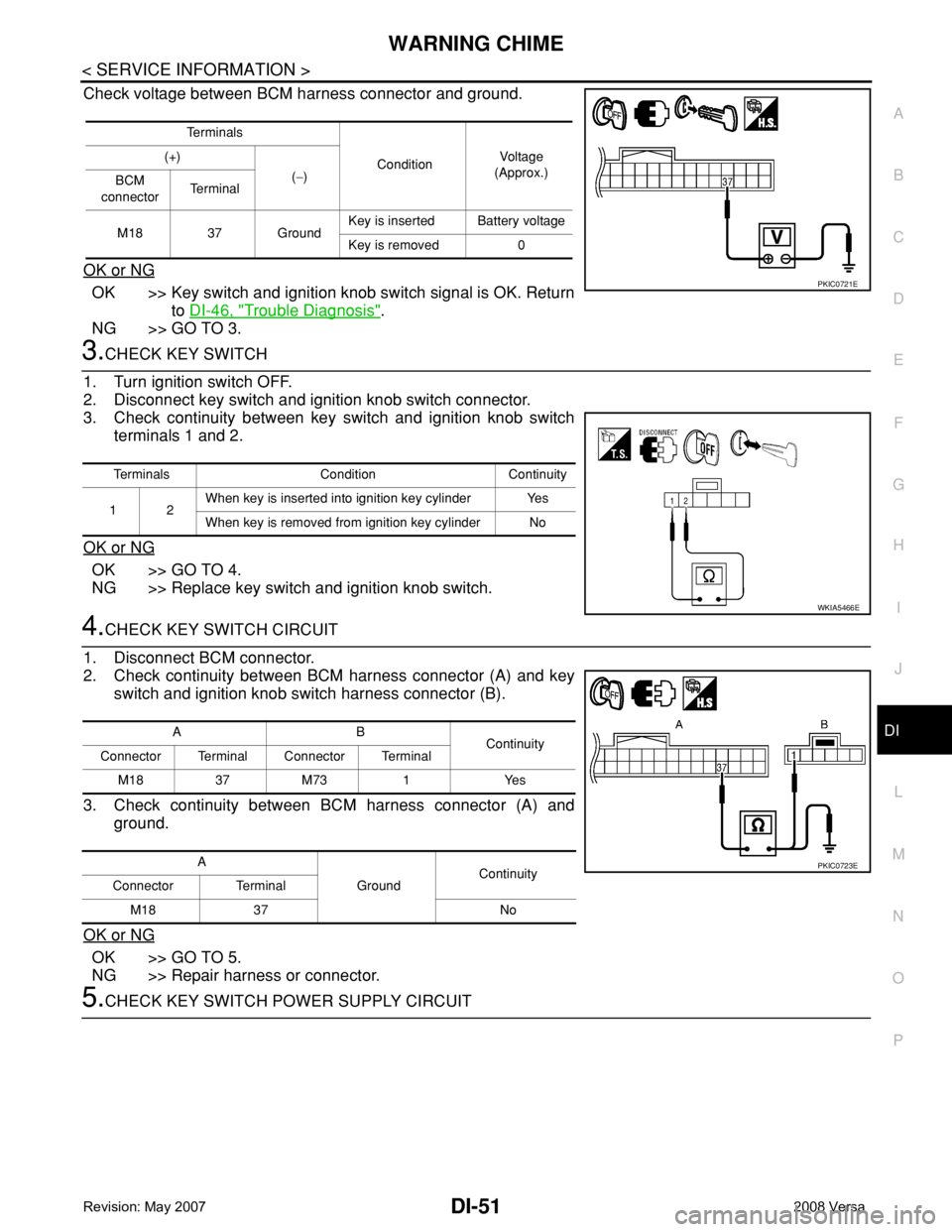
Check voltage between BCM harness connector and ground.
OK or NG
OK >> Key switch and ignition knob switch signal is OK. Return
to DI-46, "
Trouble Diagnosis".
NG >> GO TO 3.
3.CHECK KEY SWITCH
1. Turn ignition switch OFF.
2. Disconnect key switch and ignition knob switch connector.
3. Check continuity between key switch and ignition knob switch
terminals 1 and 2.
OK or NG
OK >> GO TO 4.
NG >> Replace key switch and ignition knob switch.
4.CHECK KEY SWITCH CIRCUIT
1. Disconnect BCM connector.
2. Check continuity between BCM harness connector (A) and key
switch and ignition knob switch harness connector (B).
3. Check continuity between BCM harness connector (A) and
ground.
OK or NG
OK >> GO TO 5.
NG >> Repair harness or connector.
5.CHECK KEY SWITCH POWER SUPPLY CIRCUIT
Te r m i n a l s
ConditionVol tag e
(Approx.) (+)
(−)
BCM
connectorTe r m i n a l
M18 37 GroundKey is inserted Battery voltage
Key is removed 0
PKIC0721E
Terminals Condition Continuity
12When key is inserted into ignition key cylinder Yes
When key is removed from ignition key cylinder No
WKIA5466E
AB
Continuity
Connector Terminal Connector Terminal
M1837M73 1 Yes
A
GroundContinuity
Connector Terminal
M18 37 No
PKIC0723E
Page 1073 of 2771
DI-52
< SERVICE INFORMATION >
WARNING CHIME
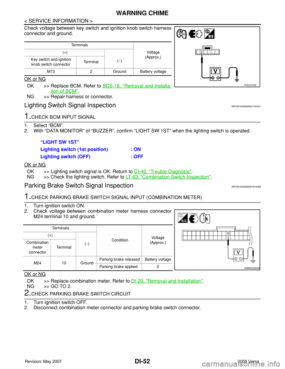
Check voltage between key switch and ignition knob switch harness
connector and ground.
OK or NG
OK >> Replace BCM. Refer to BCS-18, "Removal and Installa-
tion of BCM".
NG >> Repair harness or connector.
Lighting Switch Signal InspectionINFOID:0000000001704531
1.CHECK BCM INPUT SIGNAL
1. Select “BCM”.
2. With “DATA MONITOR” of “BUZZER”, confirm “LIGHT SW 1ST” when the lighting switch is operated.
OK or NG
OK >> Lighting switch signal is OK. Return to DI-46, "Trouble Diagnosis".
NG >> Check the lighting switch. Refer to LT-63, "
Combination Switch Inspection".
Parking Brake Switch Signal InspectionINFOID:0000000001815489
1.CHECK PARKING BRAKE SWITCH SIGNAL INPUT (COMBINATION METER)
1. Turn ignition switch ON.
2. Check voltage between combination meter harness connector
M24 terminal 10 and ground.
OK or NG
OK >> Replace combination meter. Refer to DI-20, "Removal and Installation".
NG >> GO TO 2.
2.CHECK PARKING BRAKE SWITCH CIRCUIT
1. Turn ignition switch OFF.
2. Disconnect combination meter connector and parking brake switch connector.
Te r m i n a l s
Vo l ta g e
(Approx.) (+)
(−) Key switch and ignition
knob switch connector Te r m i n a l
M73 2 Ground Battery voltage
PKIC0724E
“LIGHT SW 1ST”
Lighting switch (1st position) : ON
Lighting switch (OFF) : OFF
Te r m i n a l s
ConditionVoltag e
(Approx.) (+)
(−) Combination
meter
connectorTe r m i n a l
M24 10 GroundParking brake released Battery voltage
Parking brake applied 0
AWMIA0066GB
Page 1075 of 2771

EC-1
ENGINE
C
D
E
F
G
H
I
J
K
L
M
SECTION EC
A
EC
N
O
P
CONTENTS
ENGINE CONTROL SYSTEM
SERVICE INFORMATION ............................9
INDEX FOR DTC .................................................9
DTC No. Index ..........................................................9
Alphabetical Index ...................................................12
PRECAUTIONS ..................................................16
Precaution for Supplemental Restraint System
(SRS) "AIR BAG" and "SEAT BELT PRE-TEN-
SIONER" .................................................................
16
Precaution for Procedure without Cowl Top Cover ....16
On Board Diagnosis (OBD) System of Engine and
A/T, CVT .................................................................
16
Precaution ...............................................................17
PREPARATION ..................................................20
Special Service Tool ...............................................20
Commercial Service Tool ........................................21
ENGINE CONTROL SYSTEM ............................22
Schematic ...............................................................22
Multiport Fuel Injection (MFI) System .....................22
Electronic Ignition (EI) System ................................25
Fuel Cut Control (at No Load and High Engine
Speed) .....................................................................
25
AIR CONDITIONING CUT CONTROL ...............27
Input/Output Signal Chart ........................................27
System Description .................................................27
AUTOMATIC SPEED CONTROL DEVICE
(ASCD) ...............................................................
28
System Description .................................................28
Component Description ...........................................29
CAN COMMUNICATION ....................................30
System Description .................................................30
EVAPORATIVE EMISSION SYSTEM ................31
Description ..............................................................31
Component Inspection ............................................33
Removal and Installation .........................................35
How to Detect Fuel Vapor Leakage .........................35
ON BOARD REFUELING VAPOR RECOV-
ERY (ORVR) ......................................................
38
System Description ..................................................38
Diagnosis Procedure ...............................................38
Component Inspection .............................................40
POSITIVE CRANKCASE VENTILATION .........43
Description ...............................................................43
Component Inspection .............................................43
NVIS (NISSAN VEHICLE IMMOBILIZER SYS-
TEM-NATS) .......................................................
45
Description ...............................................................45
ON BOARD DIAGNOSTIC (OBD) SYSTEM ....46
Introduction ..............................................................46
Two Trip Detection Logic .........................................46
Emission-related Diagnostic Information .................47
Malfunction Indicator Lamp (MIL) ............................60
OBD System Operation Chart .................................63
BASIC SERVICE PROCEDURE .......................69
Basic Inspection ......................................................69
Idle Speed and Ignition Timing Check .....................73
Procedure After Replacing ECM .............................75
VIN Registration ......................................................75
Accelerator Pedal Released Position Learning .......76
Throttle Valve Closed Position Learning .................76
Idle Air Volume Learning .........................................76
Fuel Pressure Check ...............................................78
TROUBLE DIAGNOSIS ....................................81
Trouble Diagnosis Introduction ................................81
DTC Inspection Priority Chart ..................................86
Fail-Safe Chart ........................................................87
Symptom Matrix Chart .............................................88
Engine Control Component Parts Location .............93
Vacuum Hose Drawing ............................................99
Circuit Diagram ......................................................100
ECM Harness Connector Terminal Layout ............102
Page 1081 of 2771

EC-7
C
D
E
F
G
H
I
J
K
L
M
ECA
N
O
P
DTC P2119 ELECTRIC THROTTLE CON-
TROL ACTUATOR ...........................................
472
Component Description .........................................472
On Board Diagnosis Logic ....................................472
DTC Confirmation Procedure ................................472
Diagnosis Procedure .............................................473
DTC P2122, P2123 APP SENSOR ..................474
Component Description .........................................474
CONSULT-II Reference Value in Data Monitor
Mode .....................................................................
474
On Board Diagnosis Logic ....................................474
DTC Confirmation Procedure ................................474
Wiring Diagram .....................................................476
Diagnosis Procedure .............................................477
Component Inspection ..........................................479
Removal and Installation .......................................479
DTC P2127, P2128 APP SENSOR ..................480
Component Description .........................................480
CONSULT-II Reference Value in Data Monitor
Mode .....................................................................
480
On Board Diagnosis Logic ....................................480
DTC Confirmation Procedure ................................481
Wiring Diagram .....................................................482
Diagnosis Procedure .............................................483
Component Inspection ..........................................485
Removal and Installation .......................................486
DTC P2135 TP SENSOR .................................487
Component Description .........................................487
CONSULT-II Reference Value in Data Monitor
Mode .....................................................................
487
On Board Diagnosis Logic ....................................487
DTC Confirmation Procedure ................................487
Wiring Diagram .....................................................489
Diagnosis Procedure .............................................490
Component Inspection ..........................................492
Removal and Installation .......................................492
DTC P2138 APP SENSOR ...............................493
Component Description .........................................493
CONSULT-II Reference Value in Data Monitor
Mode .....................................................................
493
On Board Diagnosis Logic ....................................493
DTC Confirmation Procedure ................................494
Wiring Diagram .....................................................495
Diagnosis Procedure .............................................496
Component Inspection ..........................................499
Removal and Installation .......................................499
DTC P2A00 A/F SENSOR 1 .............................500
Component Description .........................................500
CONSULT-II Reference Value in Data Monitor
Mode .....................................................................
500
On Board Diagnosis Logic ....................................500
DTC Confirmation Procedure ................................500
Wiring Diagram .....................................................502
Diagnosis Procedure .............................................503
Removal and Installation .......................................507
ASCD BRAKE SWITCH ..................................508
Component Description .........................................508
CONSULT-II Reference Value in Data Monitor
Mode ......................................................................
508
Wiring Diagram ......................................................509
Diagnosis Procedure .............................................510
Component Inspection ...........................................514
ASCD INDICATOR ..........................................516
Component Description .........................................516
CONSULT-II Reference Value in Data Monitor
Mode ......................................................................
516
Wiring Diagram ......................................................517
Diagnosis Procedure .............................................517
ELECTRICAL LOAD SIGNAL ........................519
CONSULT-II Reference Value in Data Monitor
Mode ......................................................................
519
Diagnosis Procedure .............................................519
FUEL INJECTOR ............................................521
Component Description .........................................521
CONSULT-II Reference Value in Data Monitor
Mode ......................................................................
521
Wiring Diagram ......................................................522
Diagnosis Procedure .............................................523
Component Inspection ...........................................525
Removal and Installation .......................................525
FUEL PUMP ....................................................526
Description .............................................................526
CONSULT-II Reference Value in Data Monitor
Mode ......................................................................
526
Wiring Diagram ......................................................527
Diagnosis Procedure .............................................528
Component Inspection ...........................................530
Removal and Installation .......................................530
IGNITION SIGNAL ..........................................531
Component Description .........................................531
Wiring Diagram ......................................................532
Diagnosis Procedure .............................................535
Component Inspection ...........................................538
Removal and Installation .......................................540
REFRIGERANT PRESSURE SENSOR ..........541
Component Description .........................................541
Wiring Diagram ......................................................542
Diagnosis Procedure .............................................543
Removal and Installation .......................................545
MIL AND DATA LINK CONNECTOR .............546
Wiring Diagram ......................................................546
SERVICE DATA AND SPECIFICATIONS
(SDS) ...............................................................
548
Fuel Pressure ........................................................548
Idle Speed and Ignition Timing ..............................548
Calculated Load Value ..........................................548
Mass Air Flow Sensor ............................................548
Intake Air Temperature Sensor .............................548
Page 1090 of 2771
EC-16
< SERVICE INFORMATION >
PRECAUTIONS
PRECAUTIONS
Precaution for Supplemental Restraint System (SRS) "AIR BAG" and "SEAT BELT
PRE-TENSIONER"
INFOID:0000000001702548
The Supplemental Restraint System such as “AIR BAG” and “SEAT BELT PRE-TENSIONER”, used along
with a front seat belt, helps to reduce the risk or severity of injury to the driver and front passenger for certain
types of collision. This system includes seat belt switch inputs and dual stage front air bag modules. The SRS
system uses the seat belt switches to determine the front air bag deployment, and may only deploy one front
air bag, depending on the severity of a collision and whether the front occupants are belted or unbelted.
Information necessary to service the system safely is included in the SRS and SB section of this Service Man-
ual.
WARNING:
• To avoid rendering the SRS inoperative, which could increase the risk of personal injury or death in
the event of a collision which would result in air bag inflation, all maintenance must be performed by
an authorized NISSAN/INFINITI dealer.
• Improper maintenance, including incorrect removal and installation of the SRS, can lead to personal
injury caused by unintentional activation of the system. For removal of Spiral Cable and Air Bag
Module, see the SRS section.
• Do not use electrical test equipment on any circuit related to the SRS unless instructed to in this
Service Manual. SRS wiring harnesses can be identified by yellow and/or orange harnesses or har-
ness connectors.
Precaution for Procedure without Cowl Top CoverINFOID:0000000001702549
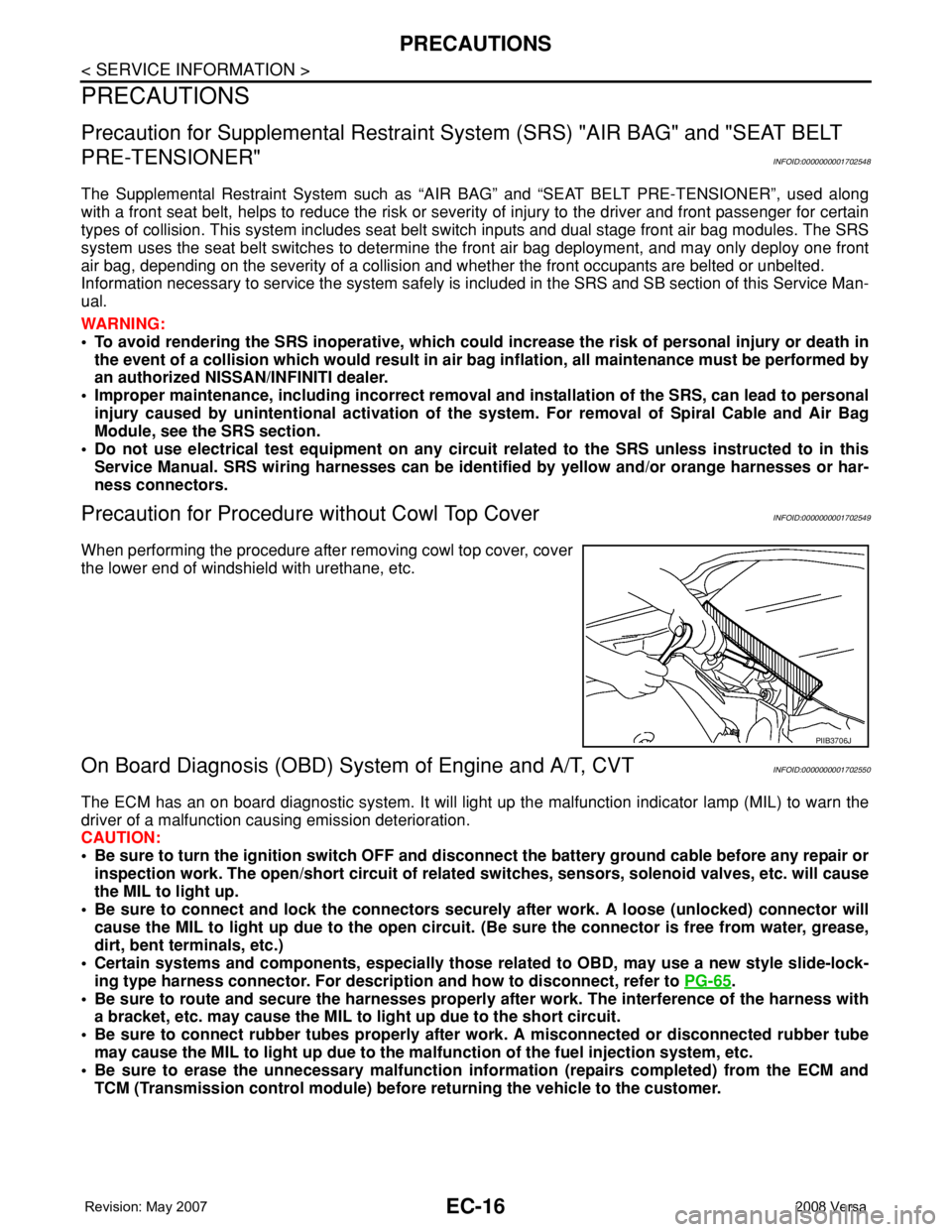
When performing the procedure after removing cowl top cover, cover
the lower end of windshield with urethane, etc.
On Board Diagnosis (OBD) System of Engine and A/T, CVTINFOID:0000000001702550
The ECM has an on board diagnostic system. It will light up the malfunction indicator lamp (MIL) to warn the
driver of a malfunction causing emission deterioration.
CAUTION:
• Be sure to turn the ignition switch OFF and disconnect the battery ground cable before any repair or
inspection work. The open/short circuit of related switches, sensors, solenoid valves, etc. will cause
the MIL to light up.
• Be sure to connect and lock the connectors securely after work. A loose (unlocked) connector will
cause the MIL to light up due to the open circuit. (Be sure the connector is free from water, grease,
dirt, bent terminals, etc.)
• Certain systems and components, especially those related to OBD, may use a new style slide-lock-
ing type harness connector. For description and how to disconnect, refer to PG-65
.
• Be sure to route and secure the harnesses properly after work. The interference of the harness with
a bracket, etc. may cause the MIL to light up due to the short circuit.
• Be sure to connect rubber tubes properly after work. A misconnected or disconnected rubber tube
may cause the MIL to light up due to the malfunction of the fuel injection system, etc.
• Be sure to erase the unnecessary malfunction information (repairs completed) from the ECM and
TCM (Transmission control module) before returning the vehicle to the customer.
PIIB3706J