2008 NISSAN LATIO ignition
[x] Cancel search: ignitionPage 1001 of 2771
CVT-162
< SERVICE INFORMATION >
CVT SHIFT LOCK SYSTEM
CVT SHIFT LOCK SYSTEM
DescriptionINFOID:0000000001703675
• The mechanical key interlock mechanism also operates as a shift lock:
With the ignition switch turned to ON, selector lever cannot be shifted from “P” position to any other position
unless brake pedal is depressed.
With the key removed, selector lever cannot be shifted from “P” position to any other position.
The key cannot be removed unless selector lever is placed in “P” position.
• The shift lock and key interlock mechanisms are controlled by the ON-OFF operation of the shift lock sole-
noid and by the operation of the rotator and slider located inside key cylinder, respectively.
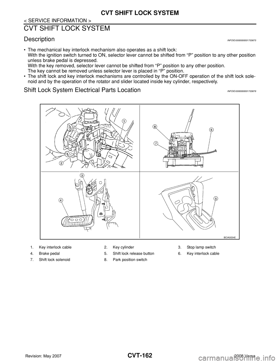
Shift Lock System Electrical Parts LocationINFOID:0000000001703676
1. Key interlock cable 2. Key cylinder 3. Stop lamp switch
4. Brake pedal 5. Shift lock release button 6. Key interlock cable
7. Shift lock solenoid 8. Park position switch
BCIA0034E
Page 1002 of 2771
CVT SHIFT LOCK SYSTEM
CVT-163
< SERVICE INFORMATION >
D
E
F
G
H
I
J
K
L
MA
B
CVT
N
O
P
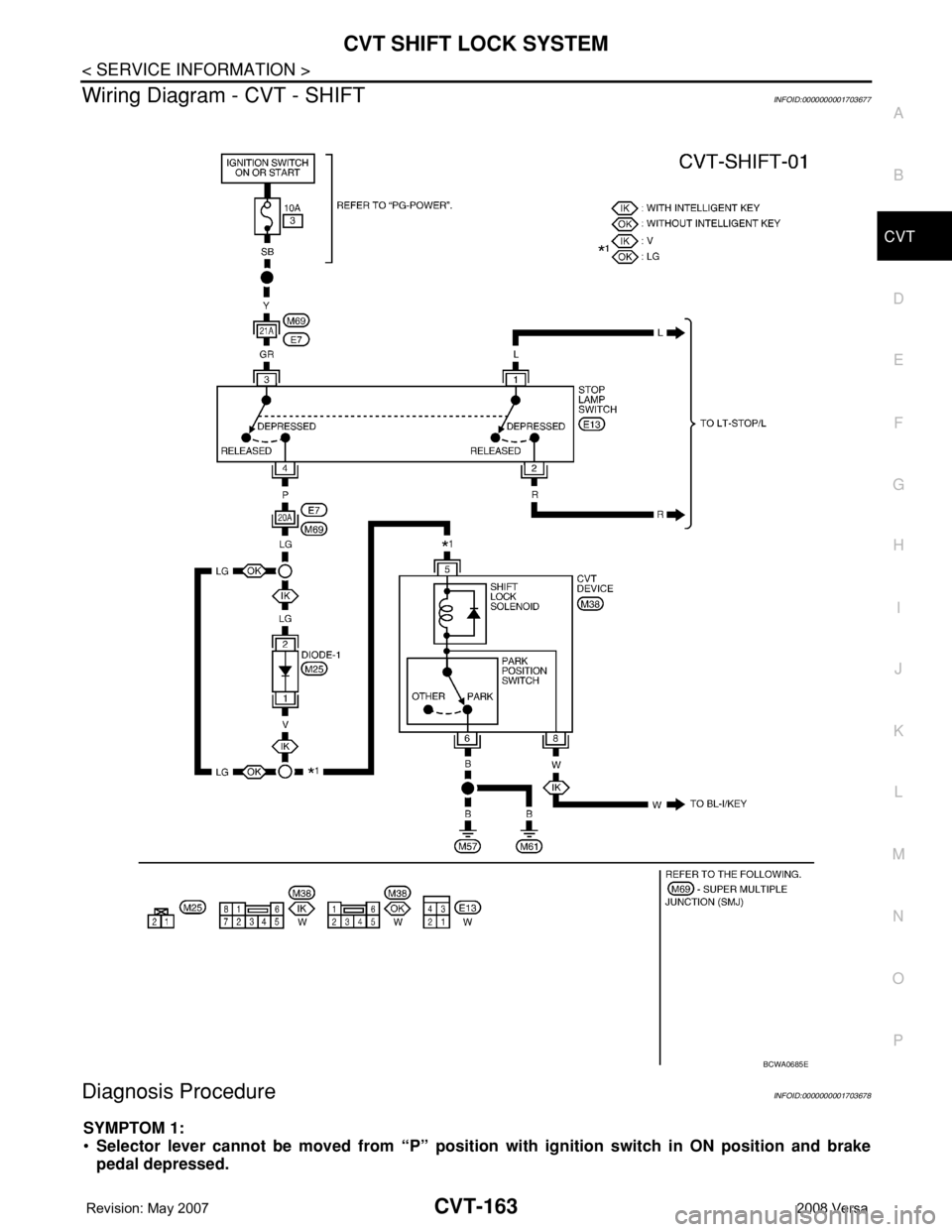
Wiring Diagram - CVT - SHIFTINFOID:0000000001703677
Diagnosis ProcedureINFOID:0000000001703678
SYMPTOM 1:
•Selector lever cannot be moved from “P” position with ignition switch in ON position and brake
pedal depressed.
BCWA0685E
Page 1003 of 2771
CVT-164
< SERVICE INFORMATION >
CVT SHIFT LOCK SYSTEM
•Selector lever can be moved from “P” position with ignition key in ON position and brake pedal
released.
•Selector lever can be moved from “P” position when ignition switch is removed from key cylinder.
SYMPTOM 2:
•Ignition key cannot be removed when selector lever is set to “P” position.
•Ignition key can be removed when selector lever is set to any position except “P” position.
1.CHECK KEY INTERLOCK CABLE
Check key interlock cable for damage.
OK or NG
OK >> GO TO 2.
NG >> Repair key interlock cable. Refer to AT-213, "
Removal and Installation".
2.CHECK CVT POSITION
Check CVT position. Refer to CVT-171, "
Checking of CVT Position".
OK or NG
OK >> GO TO 3.
NG >> Adjust control cable. Refer to CVT-171, "
Adjustment of CVT Position".
3.CHECK SHIFT LOCK SOLENOID AND PARK POSITION SWITCH
1. Turn ignition switch ON. (Do not start engine.)
2. Selector lever is set in “P” position.
3. Check operation sound.
OK or NG
OK >>INSPECTION END
NG - 1 >> With intelligent key: GO TO 4.
NG - 2 >> Without intelligent key: GO TO 5.
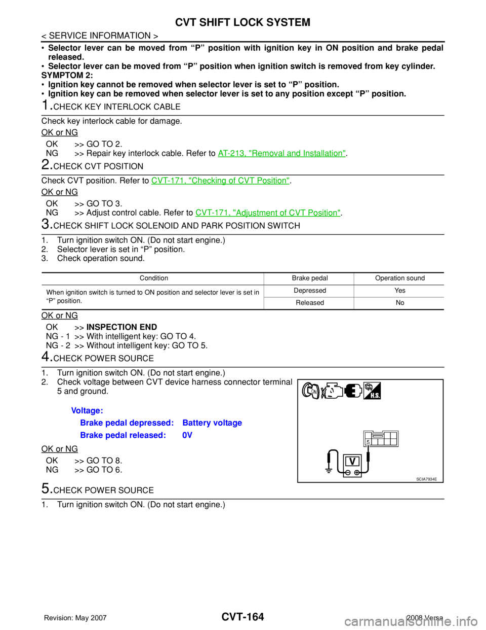
4.CHECK POWER SOURCE
1. Turn ignition switch ON. (Do not start engine.)
2. Check voltage between CVT device harness connector terminal
5 and ground.
OK or NG
OK >> GO TO 8.
NG >> GO TO 6.
5.CHECK POWER SOURCE
1. Turn ignition switch ON. (Do not start engine.)
Condition Brake pedal Operation sound
When ignition switch is turned to ON position and selector lever is set in
“P” position.Depressed Yes
Released No
Voltage:
Brake pedal depressed: Battery voltage
Brake pedal released: 0V
SCIA7934E
Page 1004 of 2771
CVT SHIFT LOCK SYSTEM
CVT-165
< SERVICE INFORMATION >
D
E
F
G
H
I
J
K
L
MA
B
CVT
N
O
P
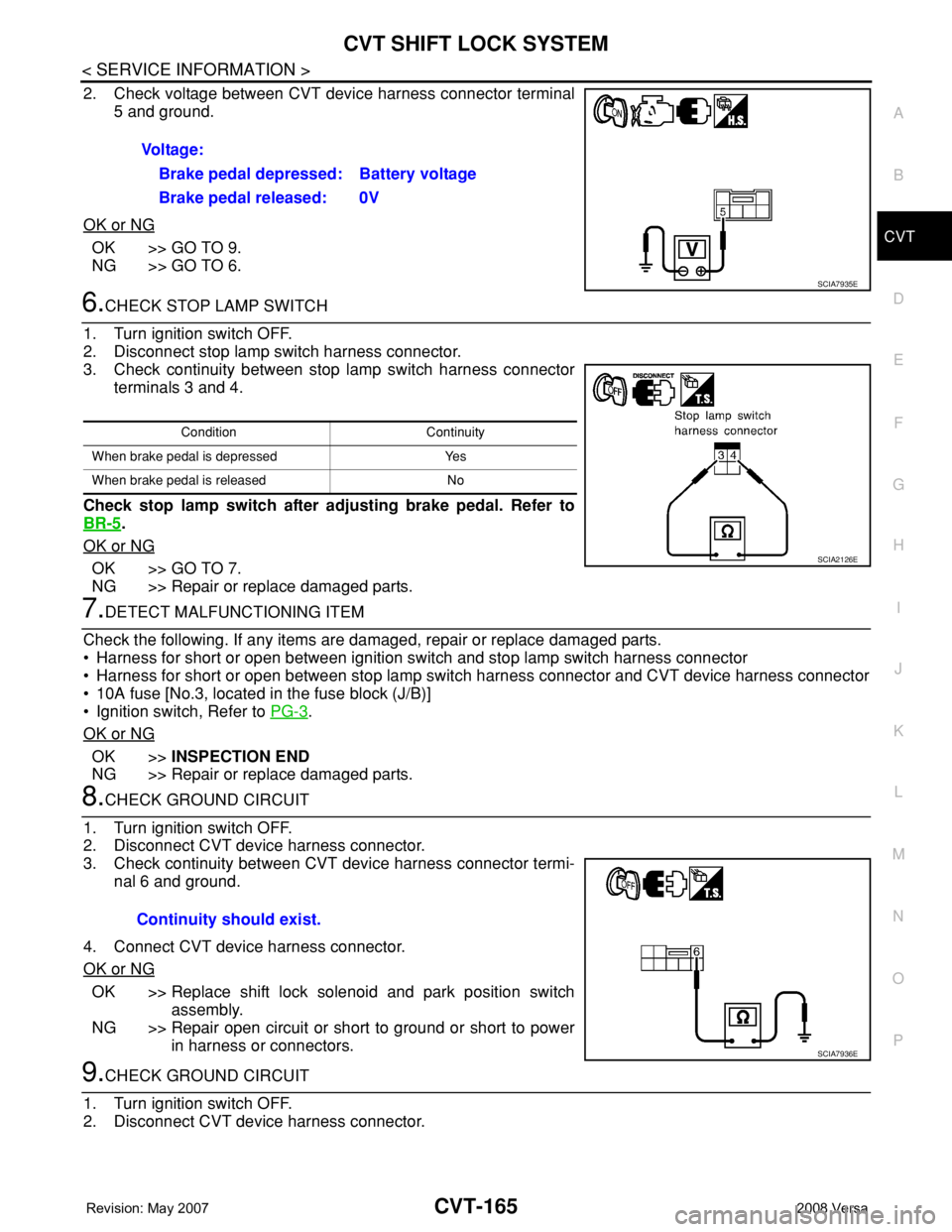
2. Check voltage between CVT device harness connector terminal
5 and ground.
OK or NG
OK >> GO TO 9.
NG >> GO TO 6.
6.CHECK STOP LAMP SWITCH
1. Turn ignition switch OFF.
2. Disconnect stop lamp switch harness connector.
3. Check continuity between stop lamp switch harness connector
terminals 3 and 4.
Check stop lamp switch after adjusting brake pedal. Refer to
BR-5
.
OK or NG
OK >> GO TO 7.
NG >> Repair or replace damaged parts.
7.DETECT MALFUNCTIONING ITEM
Check the following. If any items are damaged, repair or replace damaged parts.
• Harness for short or open between ignition switch and stop lamp switch harness connector
• Harness for short or open between stop lamp switch harness connector and CVT device harness connector
• 10A fuse [No.3, located in the fuse block (J/B)]
• Ignition switch, Refer to PG-3
.
OK or NG
OK >>INSPECTION END
NG >> Repair or replace damaged parts.
8.CHECK GROUND CIRCUIT
1. Turn ignition switch OFF.
2. Disconnect CVT device harness connector.
3. Check continuity between CVT device harness connector termi-
nal 6 and ground.
4. Connect CVT device harness connector.
OK or NG
OK >> Replace shift lock solenoid and park position switch
assembly.
NG >> Repair open circuit or short to ground or short to power
in harness or connectors.
9.CHECK GROUND CIRCUIT
1. Turn ignition switch OFF.
2. Disconnect CVT device harness connector. Voltage:
Brake pedal depressed: Battery voltage
Brake pedal released: 0V
SCIA7935E
Condition Continuity
When brake pedal is depressed Yes
When brake pedal is released No
SCIA2126E
Continuity should exist.
SCIA7936E
Page 1010 of 2771
SHIFT CONTROL SYSTEM
CVT-171
< SERVICE INFORMATION >
D
E
F
G
H
I
J
K
L
MA
B
CVT
N
O
P
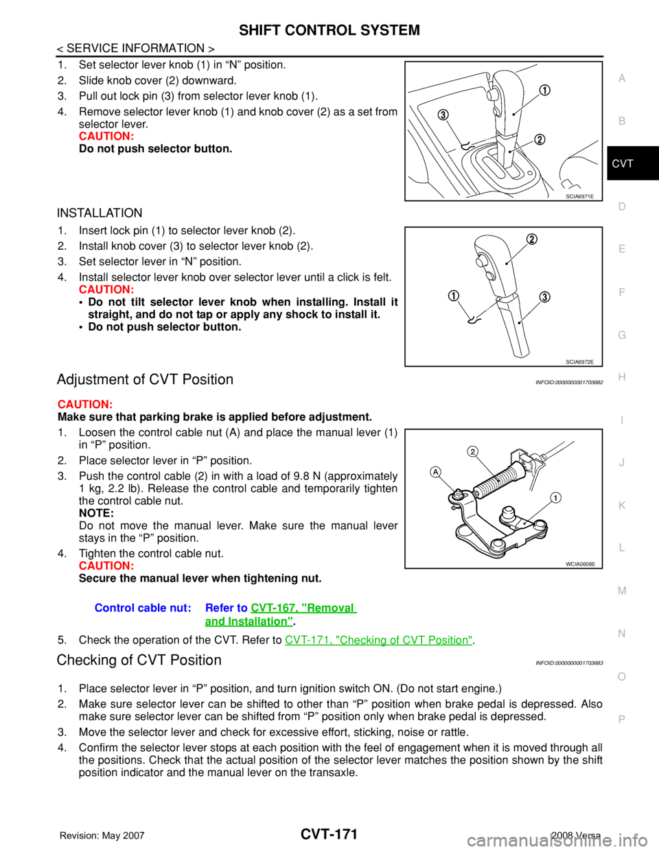
1. Set selector lever knob (1) in “N” position.
2. Slide knob cover (2) downward.
3. Pull out lock pin (3) from selector lever knob (1).
4. Remove selector lever knob (1) and knob cover (2) as a set from
selector lever.
CAUTION:
Do not push selector button.
INSTALLATION
1. Insert lock pin (1) to selector lever knob (2).
2. Install knob cover (3) to selector lever knob (2).
3. Set selector lever in “N” position.
4. Install selector lever knob over selector lever until a click is felt.
CAUTION:
• Do not tilt selector lever knob when installing. Install it
straight, and do not tap or apply any shock to install it.
• Do not push selector button.
Adjustment of CVT PositionINFOID:0000000001703682
CAUTION:
Make sure that parking brake is applied before adjustment.
1. Loosen the control cable nut (A) and place the manual lever (1)
in “P” position.
2. Place selector lever in “P” position.
3. Push the control cable (2) in with a load of 9.8 N (approximately
1 kg, 2.2 lb). Release the control cable and temporarily tighten
the control cable nut.
NOTE:
Do not move the manual lever. Make sure the manual lever
stays in the “P” position.
4. Tighten the control cable nut.
CAUTION:
Secure the manual lever when tightening nut.
5. Check the operation of the CVT. Refer to CVT-171, "
Checking of CVT Position".
Checking of CVT PositionINFOID:0000000001703683
1. Place selector lever in “P” position, and turn ignition switch ON. (Do not start engine.)
2. Make sure selector lever can be shifted to other than “P” position when brake pedal is depressed. Also
make sure selector lever can be shifted from “P” position only when brake pedal is depressed.
3. Move the selector lever and check for excessive effort, sticking, noise or rattle.
4. Confirm the selector lever stops at each position with the feel of engagement when it is moved through all
the positions. Check that the actual position of the selector lever matches the position shown by the shift
position indicator and the manual lever on the transaxle.
SCIA6971E
SCIA6972E
Control cable nut: Refer to CVT-167, "Removal
and Installation".
WCIA0608E
Page 1013 of 2771
CVT-174
< SERVICE INFORMATION >
KEY INTERLOCK CABLE
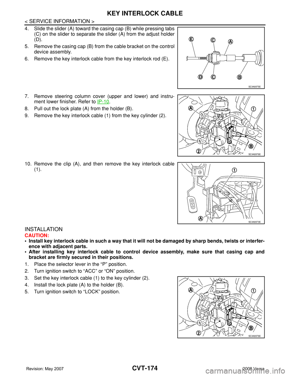
4. Slide the slider (A) toward the casing cap (B) while pressing tabs
(C) on the slider to separate the slider (A) from the adjust holder
(D).
5. Remove the casing cap (B) from the cable bracket on the control
device assembly.
6. Remove the key interlock cable from the key interlock rod (E).
7. Remove steering column cover (upper and lower) and instru-
ment lower finisher. Refer to IP-10
.
8. Pull out the lock plate (A) from the holder (B).
9. Remove the key interlock cable (1) from the key cylinder (2).
10. Remove the clip (A), and then remove the key interlock cable
(1).
INSTALLATION
CAUTION:
• Install key interlock cable in such a way that it will not be damaged by sharp bends, twists or interfer-
ence with adjacent parts.
• After installing key interlock cable to control device assembly, make sure that casing cap and
bracket are firmly secured in their positions.
1. Place the selector lever in the “P” position.
2. Turn ignition switch to “ACC” or “ON” position.
3. Set the key interlock cable (1) to the key cylinder (2).
4. Install the lock plate (A) to the holder (B).
5. Turn ignition switch to “LOCK” position.
SCIA6975E
SCIA6976E
SCIA6973E
SCIA6976E
Page 1022 of 2771

DI-1
ELECTRICAL
C
D
E
F
G
H
I
J
L
M
SECTION DI
A
B
DI
N
O
P
CONTENTS
DRIVER INFORMATION SYSTEM
SERVICE INFORMATION ............................2
PRECAUTION .....................................................2
Precaution for Supplemental Restraint System
(SRS) "AIR BAG" and "SEAT BELT PRE-TEN-
SIONER" ...................................................................
2
PREPARATION ...................................................3
Commercial Service Tool ..........................................3
COMBINATION METERS ...................................4
Component Parts and Harness Connector Loca-
tion ............................................................................
4
System Description ...................................................4
Arrangement of Combination Meter ..........................6
Internal Circuit ...........................................................7
Wiring Diagram - METER - .......................................8
Combination Meter Harness Connector Terminal
Layout .....................................................................
10
Terminal and Reference Value for Combination
Meter .......................................................................
10
Self-Diagnosis Mode of Combination Meter ............11
CONSULT-III Function (METER/M&A) ...................13
Trouble Diagnosis ...................................................14
Symptom Chart .......................................................15
Power Supply and Ground Circuit Inspection .........15
Vehicle Speed Signal Inspection .............................16
Engine Speed Signal Inspection .............................17
Fuel Level Sensor Signal Inspection .......................17
Fuel Gauge Fluctuates, Indicates Wrong Value, or
Varies ......................................................................
19
Fuel Gauge Does Not Move to Full-position ...........19
DTC [U1000] CAN Communication Circuit .............19
Electrical Component Inspection .............................19
Removal and Installation .........................................20
WARNING LAMPS .............................................21
Schematic ................................................................21
Wiring Diagram - WARN - .......................................22
Oil Pressure Warning Lamp Stays Off (Ignition
Switch ON) ..............................................................
30
Oil Pressure Warning Lamp Does Not Turn Off
(Oil Pressure Is Normal) ..........................................
32
Component Inspection .............................................32
A/T INDICATOR ................................................34
System Description ..................................................34
Wiring Diagram - AT/IND - .......................................35
A/T Indicator Does Not Illuminate ............................36
CVT INDICATOR ...............................................38
System Description ..................................................38
Wiring Diagram - CVTIND - .....................................38
CVT Indicator Does Not Illuminate ..........................39
WARNING CHIME .............................................41
Component Parts and Harness Connector Loca-
tion ...........................................................................
41
System Description ..................................................41
Wiring Diagram - CHIME - .......................................44
Terminal and Reference Value for BCM ..................45
CONSULT-III Function (BCM) .................................45
Trouble Diagnosis ....................................................46
Combination Meter Buzzer Circuit Inspection .........47
Front Door Switch LH Signal Inspection ..................48
Key Switch Signal Inspection (Without Intelligent
Key) .........................................................................
49
Key Switch and Ignition Knob Switch Signal In-
spection (With Intelligent Key, When Mechanical
Key Is Used) ............................................................
50
Lighting Switch Signal Inspection ............................52
Parking Brake Switch Signal Inspection ..................52
Electrical Component Inspection .............................53
Page 1025 of 2771
DI-4
< SERVICE INFORMATION >
COMBINATION METERS
COMBINATION METERS
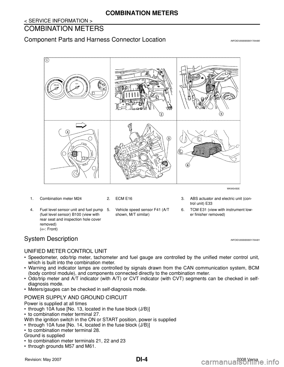
Component Parts and Harness Connector LocationINFOID:0000000001704490
System DescriptionINFOID:0000000001704491
UNIFIED METER CONTROL UNIT
• Speedometer, odo/trip meter, tachometer and fuel gauge are controlled by the unified meter control unit,
which is built into the combination meter.
• Warning and indicator lamps are controlled by signals drawn from the CAN communication system, BCM
(body control module), and components connected directly to the combination meter.
• Odo/trip meter and A/T indicator (with A/T) or CVT indicator (with CVT) segments can be checked in self-
diagnosis mode.
• Meters/gauges can be checked in self-diagnosis mode.
POWER SUPPLY AND GROUND CIRCUIT
Power is supplied at all times
• through 10A fuse [No. 13, located in the fuse block (J/B)]
• to combination meter terminal 27.
With the ignition switch in the ON or START position, power is supplied
• through 10A fuse [No. 14, located in the fuse block (J/B)]
• to combination meter terminal 28.
Ground is supplied
• to combination meter terminals 21, 22 and 23
• through grounds M57 and M61.
1. Combination meter M24 2. ECM E16 3. ABS actuator and electric unit (con-
trol unit) E33
4. Fuel level sensor unit and fuel pump
(fuel level sensor) B100 (view with
rear seat and inspection hole cover
removed)
(⇐: Front)5. Vehicle speed sensor F41 (A/T
shown, M/T similar)6. TCM E31 (view with instrument low-
er finisher removed)
WKIA5450E