2008 NISSAN LATIO battery
[x] Cancel search: batteryPage 1483 of 2771
DTC P0850 PNP SWITCH
EC-409
< SERVICE INFORMATION >
C
D
E
F
G
H
I
J
K
L
MA
EC
N
P O
>>INSPECTION END
M/T MODELS
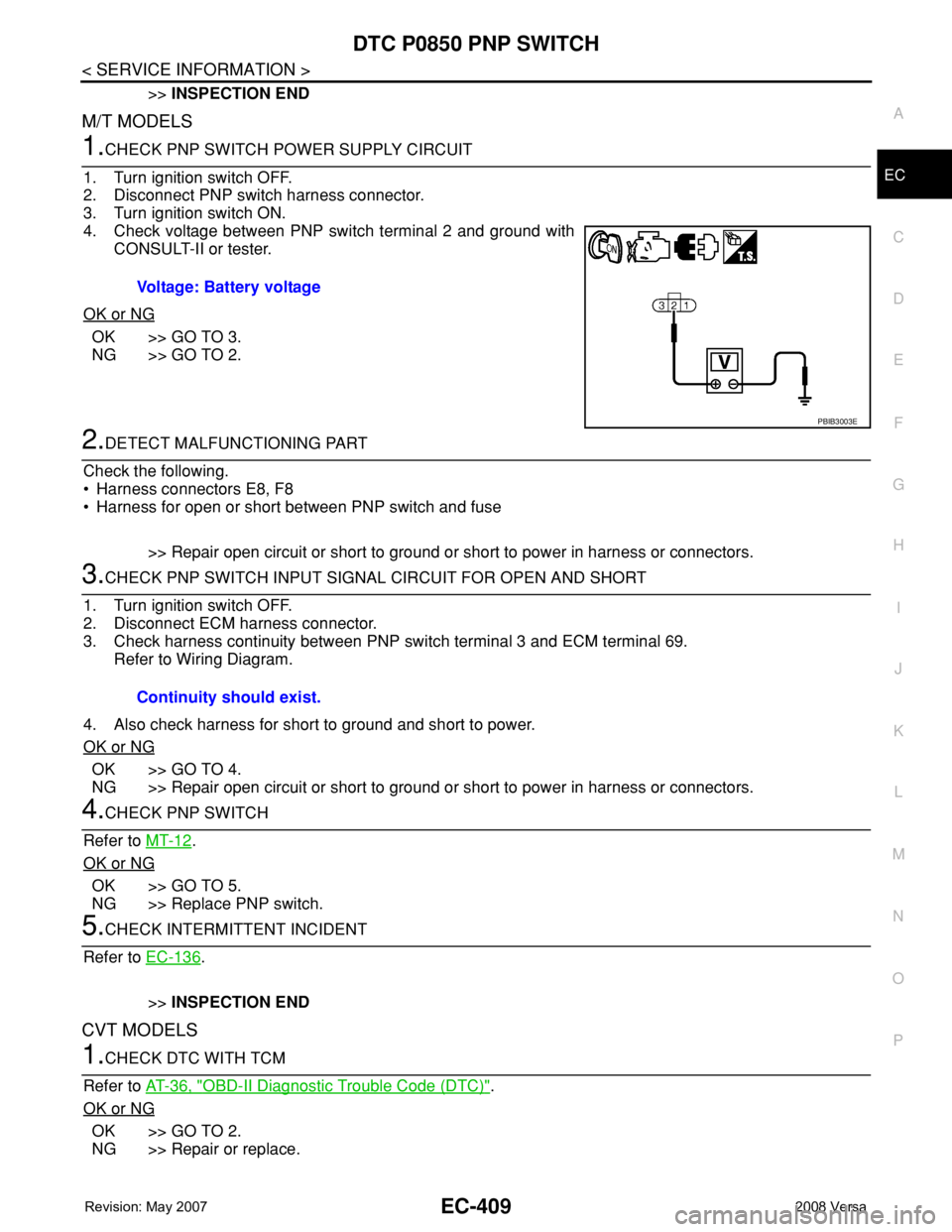
1.CHECK PNP SWITCH POWER SUPPLY CIRCUIT
1. Turn ignition switch OFF.
2. Disconnect PNP switch harness connector.
3. Turn ignition switch ON.
4. Check voltage between PNP switch terminal 2 and ground with
CONSULT-II or tester.
OK or NG
OK >> GO TO 3.
NG >> GO TO 2.
2.DETECT MALFUNCTIONING PART
Check the following.
• Harness connectors E8, F8
• Harness for open or short between PNP switch and fuse
>> Repair open circuit or short to ground or short to power in harness or connectors.
3.CHECK PNP SWITCH INPUT SIGNAL CIRCUIT FOR OPEN AND SHORT
1. Turn ignition switch OFF.
2. Disconnect ECM harness connector.
3. Check harness continuity between PNP switch terminal 3 and ECM terminal 69.
Refer to Wiring Diagram.
4. Also check harness for short to ground and short to power.
OK or NG
OK >> GO TO 4.
NG >> Repair open circuit or short to ground or short to power in harness or connectors.
4.CHECK PNP SWITCH
Refer to MT-12
.
OK or NG
OK >> GO TO 5.
NG >> Replace PNP switch.
5.CHECK INTERMITTENT INCIDENT
Refer to EC-136
.
>>INSPECTION END
CVT MODELS
1.CHECK DTC WITH TCM
Refer to AT-36, "
OBD-II Diagnostic Trouble Code (DTC)".
OK or NG
OK >> GO TO 2.
NG >> Repair or replace.Voltage: Battery voltage
PBIB3003E
Continuity should exist.
Page 1486 of 2771
EC-412
< SERVICE INFORMATION >
DTC P1217 ENGINE OVER TEMPERATURE
DTC P1217 ENGINE OVER TEMPERATURE
System DescriptionINFOID:0000000001702929
SYSTEM DESCRIPTION
NOTE:
•If DTC P1217 is displayed with DTC U1000 or U1001, first perform the trouble diagnosis for DTC
U1000, U1001. Refer to EC-143
.
•If DTC P1217 is displayed with DTC U1010, first perform the trouble diagnosis for DTC U1010. Refer
to EC-145
.
Cooling Fan Control
*1: The ECM determines the start signal status by the signals of engine speed and battery voltage.
*2: This signal is sent to ECM through CAN communication line.
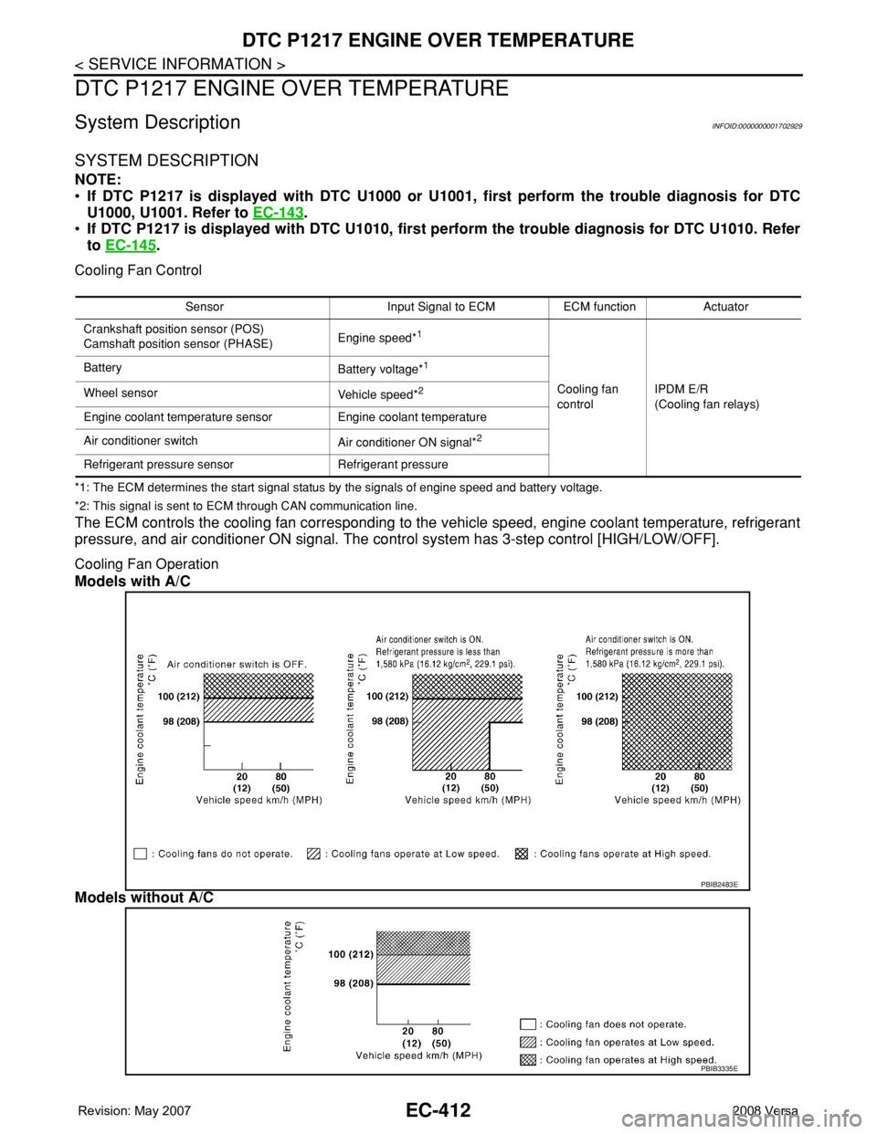
The ECM controls the cooling fan corresponding to the vehicle speed, engine coolant temperature, refrigerant
pressure, and air conditioner ON signal. The control system has 3-step control [HIGH/LOW/OFF].
Cooling Fan Operation
Models with A/C
Models without A/C
Sensor Input Signal to ECM ECM function Actuator
Crankshaft position sensor (POS)
Camshaft position sensor (PHASE)Engine speed*
1
Cooling fan
controlIPDM E/R
(Cooling fan relays) Battery
Battery voltage*
1
Wheel sensor
Vehicle speed*2
Engine coolant temperature sensor Engine coolant temperature
Air conditioner switch
Air conditioner ON signal*
2
Refrigerant pressure sensor Refrigerant pressure
PBIB2483E
PBIB3335E
Page 1494 of 2771
EC-420
< SERVICE INFORMATION >
DTC P1217 ENGINE OVER TEMPERATURE
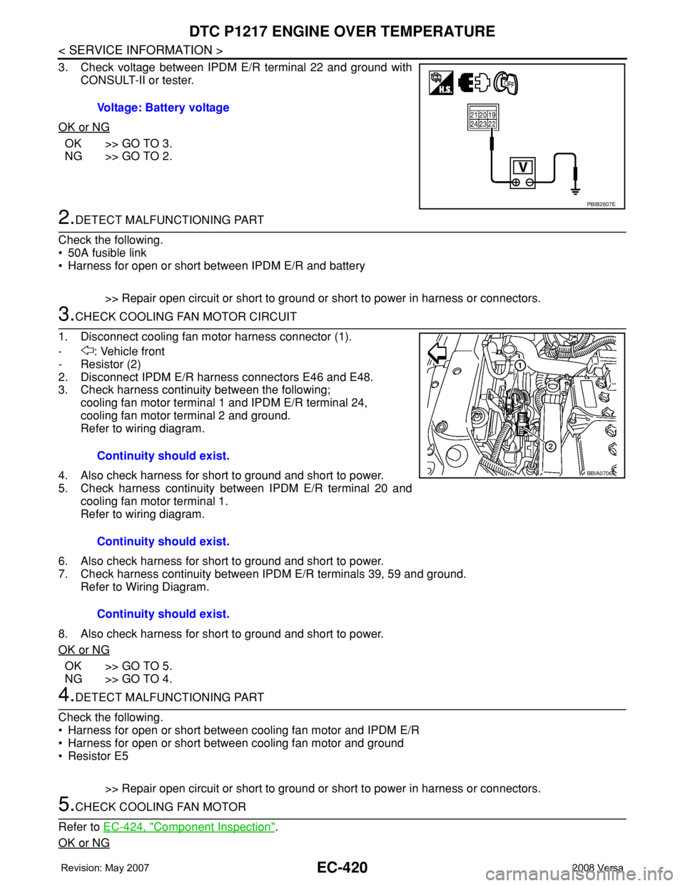
3. Check voltage between IPDM E/R terminal 22 and ground with
CONSULT-II or tester.
OK or NG
OK >> GO TO 3.
NG >> GO TO 2.
2.DETECT MALFUNCTIONING PART
Check the following.
• 50A fusible link
• Harness for open or short between IPDM E/R and battery
>> Repair open circuit or short to ground or short to power in harness or connectors.
3.CHECK COOLING FAN MOTOR CIRCUIT
1. Disconnect cooling fan motor harness connector (1).
- : Vehicle front
-Resistor (2)
2. Disconnect IPDM E/R harness connectors E46 and E48.
3. Check harness continuity between the following;
cooling fan motor terminal 1 and IPDM E/R terminal 24,
cooling fan motor terminal 2 and ground.
Refer to wiring diagram.
4. Also check harness for short to ground and short to power.
5. Check harness continuity between IPDM E/R terminal 20 and
cooling fan motor terminal 1.
Refer to wiring diagram.
6. Also check harness for short to ground and short to power.
7. Check harness continuity between IPDM E/R terminals 39, 59 and ground.
Refer to Wiring Diagram.
8. Also check harness for short to ground and short to power.
OK or NG
OK >> GO TO 5.
NG >> GO TO 4.
4.DETECT MALFUNCTIONING PART
Check the following.
• Harness for open or short between cooling fan motor and IPDM E/R
• Harness for open or short between cooling fan motor and ground
•Resistor E5
>> Repair open circuit or short to ground or short to power in harness or connectors.
5.CHECK COOLING FAN MOTOR
Refer to EC-424, "
Component Inspection".
OK or NG
Voltage: Battery voltage
PBIB2607E
Continuity should exist.
Continuity should exist.
Continuity should exist.
BBIA0706E
Page 1497 of 2771
DTC P1217 ENGINE OVER TEMPERATURE
EC-423
< SERVICE INFORMATION >
C
D
E
F
G
H
I
J
K
L
MA
EC
N
P O
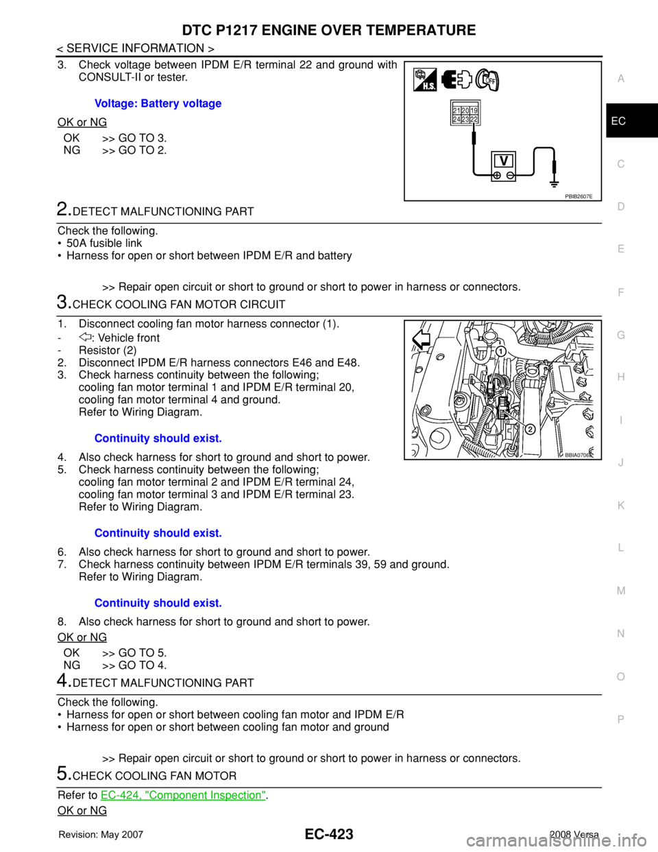
3. Check voltage between IPDM E/R terminal 22 and ground with
CONSULT-II or tester.
OK or NG
OK >> GO TO 3.
NG >> GO TO 2.
2.DETECT MALFUNCTIONING PART
Check the following.
• 50A fusible link
• Harness for open or short between IPDM E/R and battery
>> Repair open circuit or short to ground or short to power in harness or connectors.
3.CHECK COOLING FAN MOTOR CIRCUIT
1. Disconnect cooling fan motor harness connector (1).
- : Vehicle front
-Resistor (2)
2. Disconnect IPDM E/R harness connectors E46 and E48.
3. Check harness continuity between the following;
cooling fan motor terminal 1 and IPDM E/R terminal 20,
cooling fan motor terminal 4 and ground.
Refer to Wiring Diagram.
4. Also check harness for short to ground and short to power.
5. Check harness continuity between the following;
cooling fan motor terminal 2 and IPDM E/R terminal 24,
cooling fan motor terminal 3 and IPDM E/R terminal 23.
Refer to Wiring Diagram.
6. Also check harness for short to ground and short to power.
7. Check harness continuity between IPDM E/R terminals 39, 59 and ground.
Refer to Wiring Diagram.
8. Also check harness for short to ground and short to power.
OK or NG
OK >> GO TO 5.
NG >> GO TO 4.
4.DETECT MALFUNCTIONING PART
Check the following.
• Harness for open or short between cooling fan motor and IPDM E/R
• Harness for open or short between cooling fan motor and ground
>> Repair open circuit or short to ground or short to power in harness or connectors.
5.CHECK COOLING FAN MOTOR
Refer to EC-424, "
Component Inspection".
OK or NG
Voltage: Battery voltage
PBIB2607E
Continuity should exist.
Continuity should exist.
Continuity should exist.
BBIA0706E
Page 1499 of 2771
DTC P1217 ENGINE OVER TEMPERATURE
EC-425
< SERVICE INFORMATION >
C
D
E
F
G
H
I
J
K
L
MA
EC
N
P O
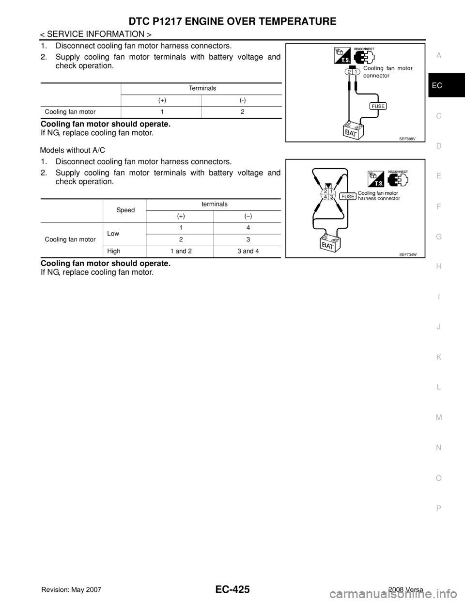
1. Disconnect cooling fan motor harness connectors.
2. Supply cooling fan motor terminals with battery voltage and
check operation.
Cooling fan motor should operate.
If NG, replace cooling fan motor.
Models without A/C
1. Disconnect cooling fan motor harness connectors.
2. Supply cooling fan motor terminals with battery voltage and
check operation.
Cooling fan motor should operate.
If NG, replace cooling fan motor.
Te r m i n a l s
(+) (-)
Cooling fan motor 1 2
SEF888V
Sp ee dterminals
(+) (−)
Cooling fan motorLow 14
23
High 1 and 2 3 and 4
SEF734W
Page 1500 of 2771
EC-426
< SERVICE INFORMATION >
DTC P1225 TP SENSOR
DTC P1225 TP SENSOR
Component DescriptionINFOID:0000000001702937
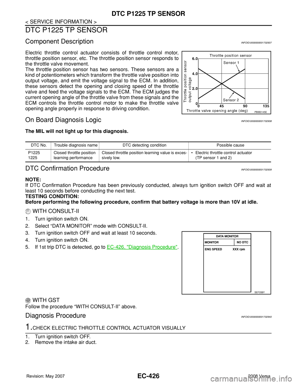
Electric throttle control actuator consists of throttle control motor,
throttle position sensor, etc. The throttle position sensor responds to
the throttle valve movement.
The throttle position sensor has two sensors. These sensors are a
kind of potentiometers which transform the throttle valve position into
output voltage, and emit the voltage signal to the ECM. In addition,
these sensors detect the opening and closing speed of the throttle
valve and feed the voltage signals to the ECM. The ECM judges the
current opening angle of the throttle valve from these signals and the
ECM controls the throttle control motor to make the throttle valve
opening angle properly in response to driving condition.
On Board Diagnosis LogicINFOID:0000000001702938
The MIL will not light up for this diagnosis.
DTC Confirmation ProcedureINFOID:0000000001702939
NOTE:
If DTC Confirmation Procedure has been previously conducted, always turn ignition switch OFF and wait at
least 10 seconds before conducting the next test.
TESTING CONDITION:
Before performing the following procedure, confirm that battery voltage is more than 10V at idle.
WITH CONSULT-II
1. Turn ignition switch ON.
2. Select “DATA MONITOR” mode with CONSULT-II.
3. Turn ignition switch OFF and wait at least 10 seconds.
4. Turn ignition switch ON.
5. If 1st trip DTC is detected, go to EC-426, "
Diagnosis Procedure".
WITH GST
Follow the procedure “WITH CONSULT-II” above.
Diagnosis ProcedureINFOID:0000000001702940
1.CHECK ELECTRIC THROTTLE CONTROL ACTUATOR VISUALLY
1. Turn ignition switch OFF.
2. Remove the intake air duct.
PBIB0145E
DTC No. Trouble diagnosis name DTC detecting condition Possible cause
P1225
1225Closed throttle position
learning performanceClosed throttle position learning value is exces-
sively low.• Electric throttle control actuator
(TP sensor 1 and 2)
SEF058Y
Page 1502 of 2771
EC-428
< SERVICE INFORMATION >
DTC P1226 TP SENSOR
DTC P1226 TP SENSOR
Component DescriptionINFOID:0000000001702942
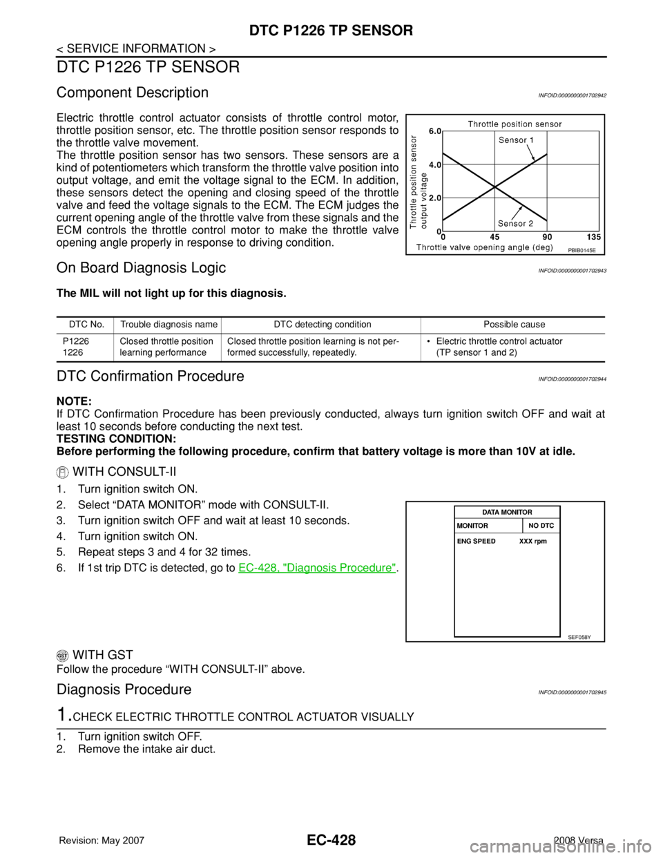
Electric throttle control actuator consists of throttle control motor,
throttle position sensor, etc. The throttle position sensor responds to
the throttle valve movement.
The throttle position sensor has two sensors. These sensors are a
kind of potentiometers which transform the throttle valve position into
output voltage, and emit the voltage signal to the ECM. In addition,
these sensors detect the opening and closing speed of the throttle
valve and feed the voltage signals to the ECM. The ECM judges the
current opening angle of the throttle valve from these signals and the
ECM controls the throttle control motor to make the throttle valve
opening angle properly in response to driving condition.
On Board Diagnosis LogicINFOID:0000000001702943
The MIL will not light up for this diagnosis.
DTC Confirmation ProcedureINFOID:0000000001702944
NOTE:
If DTC Confirmation Procedure has been previously conducted, always turn ignition switch OFF and wait at
least 10 seconds before conducting the next test.
TESTING CONDITION:
Before performing the following procedure, confirm that battery voltage is more than 10V at idle.
WITH CONSULT-II
1. Turn ignition switch ON.
2. Select “DATA MONITOR” mode with CONSULT-II.
3. Turn ignition switch OFF and wait at least 10 seconds.
4. Turn ignition switch ON.
5. Repeat steps 3 and 4 for 32 times.
6. If 1st trip DTC is detected, go to EC-428, "
Diagnosis Procedure".
WITH GST
Follow the procedure “WITH CONSULT-II” above.
Diagnosis ProcedureINFOID:0000000001702945
1.CHECK ELECTRIC THROTTLE CONTROL ACTUATOR VISUALLY
1. Turn ignition switch OFF.
2. Remove the intake air duct.
PBIB0145E
DTC No. Trouble diagnosis name DTC detecting condition Possible cause
P1226
1226Closed throttle position
learning performanceClosed throttle position learning is not per-
formed successfully, repeatedly.• Electric throttle control actuator
(TP sensor 1 and 2)
SEF058Y
Page 1504 of 2771
EC-430
< SERVICE INFORMATION >
DTC P1421 COLD START CONTROL
DTC P1421 COLD START CONTROL
DescriptionINFOID:0000000001702947
ECM controls ignition timing and engine idle speed when engine is started with prewarming up condition.
This control promotes the activation of three way catalyst by heating the catalyst and reduces emissions.
On Board Diagnosis LogicINFOID:0000000001702948
DTC Confirmation ProcedureINFOID:0000000001702949
NOTE:
• If DTC Confirmation Procedure has been previously conducted, always turn ignition switch OFF and wait at
least 10 seconds before conducting the next test.
•If DTC P1421 is displayed with other DTC, first perform the trouble diagnosis for other DTC.
TESTING CONDITION:
Before performing the following procedure, confirm that battery voltage is more than 11V at idle.
WITH CONSULT-II
1. Turn ignition switch OFF and wait at least 10 seconds.
2. Turn ignition switch ON.
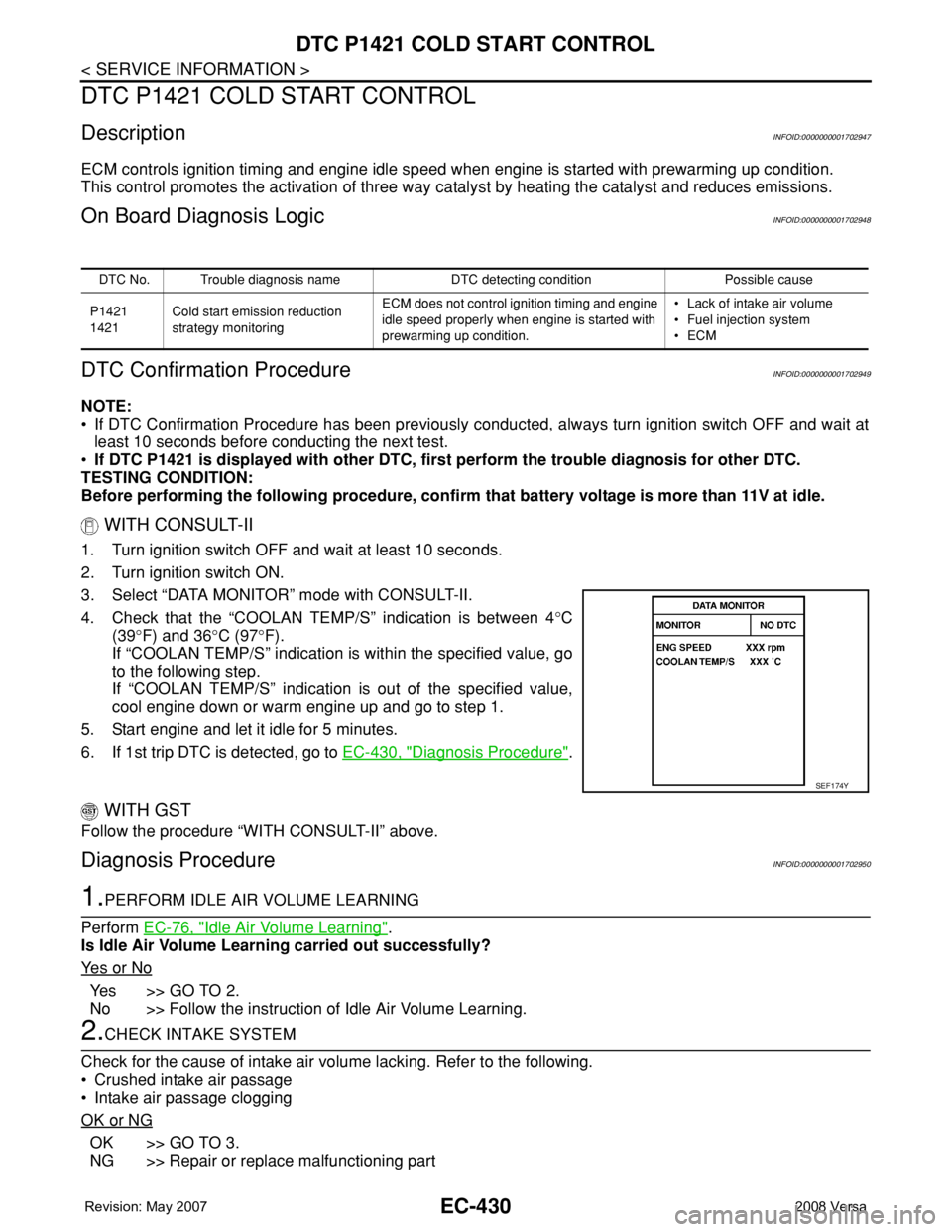
3. Select “DATA MONITOR” mode with CONSULT-II.
4. Check that the “COOLAN TEMP/S” indication is between 4°C
(39°F) and 36°C (97°F).
If “COOLAN TEMP/S” indication is within the specified value, go
to the following step.
If “COOLAN TEMP/S” indication is out of the specified value,
cool engine down or warm engine up and go to step 1.
5. Start engine and let it idle for 5 minutes.
6. If 1st trip DTC is detected, go to EC-430, "
Diagnosis Procedure".
WITH GST
Follow the procedure “WITH CONSULT-II” above.
Diagnosis ProcedureINFOID:0000000001702950
1.PERFORM IDLE AIR VOLUME LEARNING
Perform EC-76, "
Idle Air Volume Learning".
Is Idle Air Volume Learning carried out successfully?
Ye s o r N o
Ye s > > G O T O 2 .
No >> Follow the instruction of Idle Air Volume Learning.
2.CHECK INTAKE SYSTEM
Check for the cause of intake air volume lacking. Refer to the following.
• Crushed intake air passage
• Intake air passage clogging
OK or NG
OK >> GO TO 3.
NG >> Repair or replace malfunctioning part
DTC No. Trouble diagnosis name DTC detecting condition Possible cause
P1421
1421Cold start emission reduction
strategy monitoringECM does not control ignition timing and engine
idle speed properly when engine is started with
prewarming up condition.• Lack of intake air volume
• Fuel injection system
•ECM
SEF174Y