2008 NISSAN LATIO wiring diagram
[x] Cancel search: wiring diagramPage 1992 of 2771
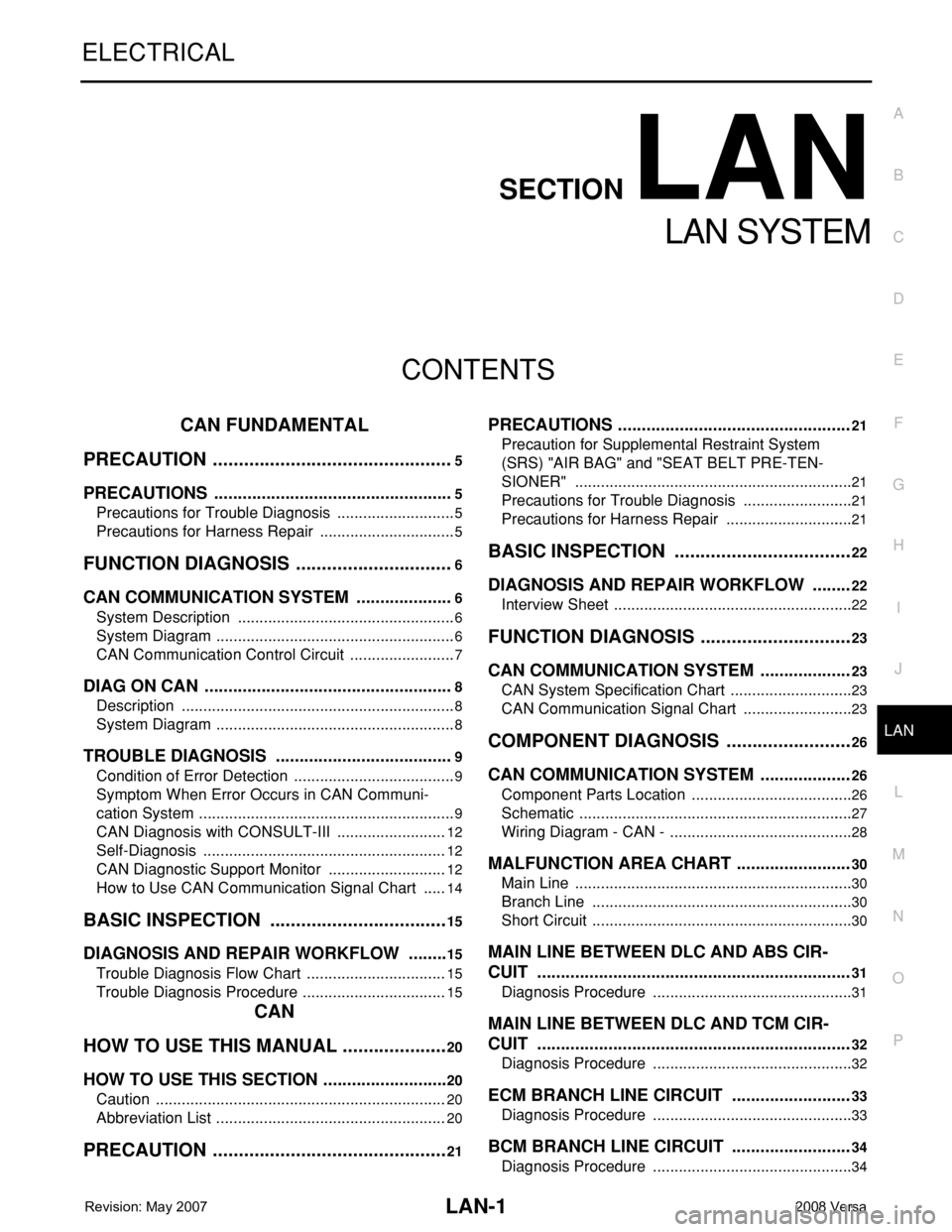
LAN-1
ELECTRICAL
C
D
E
F
G
H
I
J
L
M
SECTION LAN
A
B
LAN
N
O
P
CONTENTS
LAN SYSTEM
CAN FUNDAMENTAL
PRECAUTION ...............................................
5
PRECAUTIONS ...................................................5
Precautions for Trouble Diagnosis ............................5
Precautions for Harness Repair ................................5
FUNCTION DIAGNOSIS ...............................6
CAN COMMUNICATION SYSTEM .....................6
System Description ...................................................6
System Diagram ........................................................6
CAN Communication Control Circuit .........................7
DIAG ON CAN .....................................................8
Description ................................................................8
System Diagram ........................................................8
TROUBLE DIAGNOSIS ......................................9
Condition of Error Detection ......................................9
Symptom When Error Occurs in CAN Communi-
cation System ............................................................
9
CAN Diagnosis with CONSULT-III ..........................12
Self-Diagnosis .........................................................12
CAN Diagnostic Support Monitor ............................12
How to Use CAN Communication Signal Chart ......14
BASIC INSPECTION ...................................15
DIAGNOSIS AND REPAIR WORKFLOW .........15
Trouble Diagnosis Flow Chart .................................15
Trouble Diagnosis Procedure ..................................15
CAN
HOW TO USE THIS MANUAL .....................
20
HOW TO USE THIS SECTION ...........................20
Caution ....................................................................20
Abbreviation List ......................................................20
PRECAUTION ..............................................21
PRECAUTIONS .................................................21
Precaution for Supplemental Restraint System
(SRS) "AIR BAG" and "SEAT BELT PRE-TEN-
SIONER" .................................................................
21
Precautions for Trouble Diagnosis ..........................21
Precautions for Harness Repair ..............................21
BASIC INSPECTION ...................................22
DIAGNOSIS AND REPAIR WORKFLOW ........22
Interview Sheet ........................................................22
FUNCTION DIAGNOSIS ..............................23
CAN COMMUNICATION SYSTEM ...................23
CAN System Specification Chart .............................23
CAN Communication Signal Chart ..........................23
COMPONENT DIAGNOSIS .........................26
CAN COMMUNICATION SYSTEM ...................26
Component Parts Location ......................................26
Schematic ................................................................27
Wiring Diagram - CAN - ...........................................28
MALFUNCTION AREA CHART ........................30
Main Line .................................................................30
Branch Line .............................................................30
Short Circuit .............................................................30
MAIN LINE BETWEEN DLC AND ABS CIR-
CUIT ..................................................................
31
Diagnosis Procedure ...............................................31
MAIN LINE BETWEEN DLC AND TCM CIR-
CUIT ..................................................................
32
Diagnosis Procedure ...............................................32
ECM BRANCH LINE CIRCUIT .........................33
Diagnosis Procedure ...............................................33
BCM BRANCH LINE CIRCUIT .........................34
Diagnosis Procedure ...............................................34
Page 2019 of 2771
![NISSAN LATIO 2008 Service Repair Manual LAN-28
< COMPONENT DIAGNOSIS >[CAN]
CAN COMMUNICATION SYSTEM
Wiring Diagram - CAN -
INFOID:0000000001711222
BKWA0820E NISSAN LATIO 2008 Service Repair Manual LAN-28
< COMPONENT DIAGNOSIS >[CAN]
CAN COMMUNICATION SYSTEM
Wiring Diagram - CAN -
INFOID:0000000001711222
BKWA0820E](/manual-img/5/57360/w960_57360-2018.png)
LAN-28
< COMPONENT DIAGNOSIS >[CAN]
CAN COMMUNICATION SYSTEM
Wiring Diagram - CAN -
INFOID:0000000001711222
BKWA0820E
Page 2138 of 2771
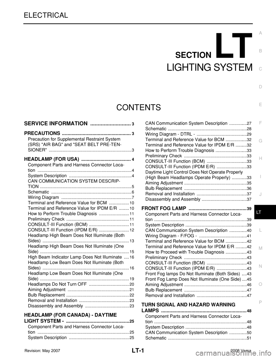
LT-1
ELECTRICAL
C
D
E
F
G
H
I
J
L
M
SECTION LT
A
B
LT
N
O
P
CONTENTS
LIGHTING SYSTEM
SERVICE INFORMATION ............................3
PRECAUTIONS ...................................................3
Precaution for Supplemental Restraint System
(SRS) "AIR BAG" and "SEAT BELT PRE-TEN-
SIONER" ...................................................................
3
HEADLAMP (FOR USA) .....................................4
Component Parts and Harness Connector Loca-
tion ............................................................................
4
System Description ...................................................4
CAN COMMUNICATION SYSTEM DESCRIP-
TION ..........................................................................
5
Schematic .................................................................6
Wiring Diagram .........................................................7
Terminal and Reference Value for BCM .................10
Terminal and Reference Value for IPDM E/R .........10
How to Perform Trouble Diagnosis .........................11
Preliminary Check ...................................................11
CONSULT-III Function (BCM) .................................11
CONSULT-III Function (IPDM E/R) .........................12
Headlamp High Beam Does Not Illuminate (Both
Sides) ......................................................................
13
Headlamp High Beam Does Not Illuminate (One
Side) ........................................................................
15
High Beam Indicator Lamp Does Not Illuminate .....16
Headlamp Low Beam Does Not Illuminate (Both
Sides) ......................................................................
16
Headlamp Low Beam Does Not Illuminate (One
Side) ........................................................................
19
Headlamps Do Not Turn OFF .................................20
Aiming Adjustment ..................................................21
Bulb Replacement ...................................................22
Removal and Installation .........................................23
Disassembly and Assembly ....................................23
HEADLAMP (FOR CANADA) - DAYTIME
LIGHT SYSTEM - ...............................................
25
Component Parts and Harness Connector Loca-
tion ..........................................................................
25
System Description .................................................25
CAN Communication System Description ...............27
Schematic ................................................................28
Wiring Diagram - DTRL - .........................................29
Terminal and Reference Value for BCM ..................32
Terminal and Reference Value for IPDM E/R ..........32
How to Perform Trouble Diagnosis ..........................33
Preliminary Check ...................................................33
CONSULT-III Function (BCM) .................................33
CONSULT-III Function (IPDM E/R) .........................33
Daytime Light Control Does Not Operate Properly
(High Beam Headlamps Operate Properly) .............
33
Aiming Adjustment ...................................................35
Bulb Replacement ...................................................36
Removal and Installation .........................................37
Disassembly and Assembly .....................................37
FRONT FOG LAMP ..........................................39
Component Parts and Harness Connector Loca-
tion ...........................................................................
39
System Description ..................................................39
CAN Communication System Description ...............40
Wiring Diagram - F/FOG - .......................................41
Terminal and Reference Value for BCM ..................42
Terminal and Reference Value for IPDM E/R ..........42
How to Proceed with Trouble Diagnosis ..................43
Preliminary Check ...................................................43
CONSULT-III Function (BCM) .................................43
CONSULT-III Function (IPDM E/R) .........................43
Front Fog lamps Do Not Illuminate (Both Sides) .....43
Front Fog Lamp Does Not Illuminate (One Side) ....45
Aiming Adjustment ...................................................46
Bulb Replacement ...................................................47
Removal and Installation .........................................47
TURN SIGNAL AND HAZARD WARNING
LAMPS ..............................................................
48
Component Parts and Harness Connector Loca-
tion ...........................................................................
48
System Description ..................................................48
CAN Communication System Description ...............50
Schematic ................................................................51
Page 2139 of 2771
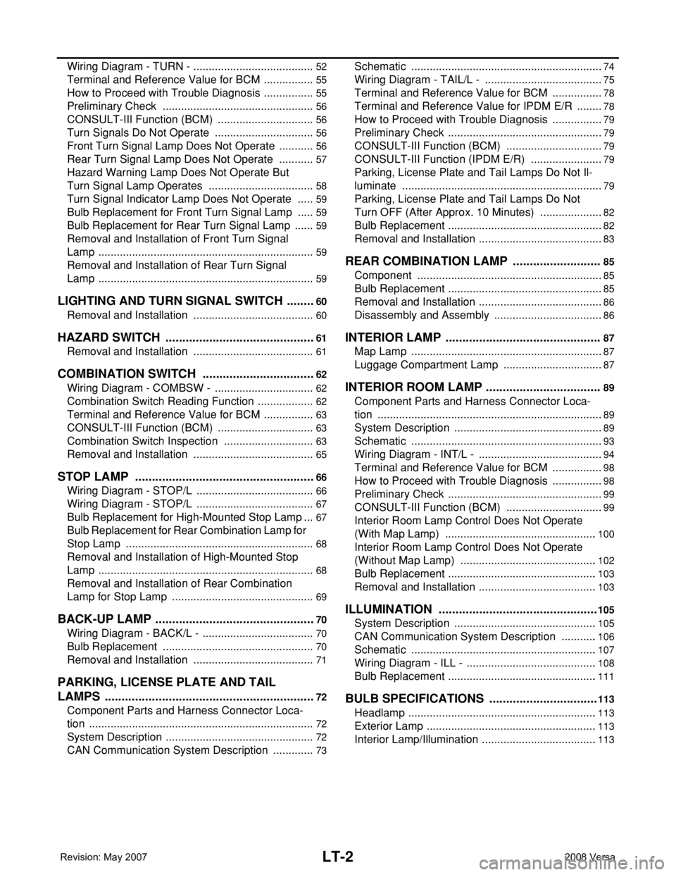
LT-2
Wiring Diagram - TURN - ........................................52
Terminal and Reference Value for BCM .................55
How to Proceed with Trouble Diagnosis .................55
Preliminary Check ..................................................56
CONSULT-III Function (BCM) ................................56
Turn Signals Do Not Operate .................................56
Front Turn Signal Lamp Does Not Operate ............56
Rear Turn Signal Lamp Does Not Operate ............57
Hazard Warning Lamp Does Not Operate But
Turn Signal Lamp Operates ...................................
58
Turn Signal Indicator Lamp Does Not Operate ......59
Bulb Replacement for Front Turn Signal Lamp ......59
Bulb Replacement for Rear Turn Signal Lamp .......59
Removal and Installation of Front Turn Signal
Lamp .......................................................................
59
Removal and Installation of Rear Turn Signal
Lamp .......................................................................
59
LIGHTING AND TURN SIGNAL SWITCH .........60
Removal and Installation ........................................60
HAZARD SWITCH .............................................61
Removal and Installation ........................................61
COMBINATION SWITCH ..................................62
Wiring Diagram - COMBSW - .................................62
Combination Switch Reading Function ...................62
Terminal and Reference Value for BCM .................63
CONSULT-III Function (BCM) ................................63
Combination Switch Inspection ..............................63
Removal and Installation ........................................65
STOP LAMP ......................................................66
Wiring Diagram - STOP/L .......................................66
Wiring Diagram - STOP/L .......................................67
Bulb Replacement for High-Mounted Stop Lamp ...67
Bulb Replacement for Rear Combination Lamp for
Stop Lamp ..............................................................
68
Removal and Installation of High-Mounted Stop
Lamp .......................................................................
68
Removal and Installation of Rear Combination
Lamp for Stop Lamp ...............................................
69
BACK-UP LAMP ................................................70
Wiring Diagram - BACK/L - .....................................70
Bulb Replacement ..................................................70
Removal and Installation ........................................71
PARKING, LICENSE PLATE AND TAIL
LAMPS ...............................................................
72
Component Parts and Harness Connector Loca-
tion ..........................................................................
72
System Description .................................................72
CAN Communication System Description ..............73
Schematic ...............................................................74
Wiring Diagram - TAIL/L - .......................................75
Terminal and Reference Value for BCM .................78
Terminal and Reference Value for IPDM E/R .........78
How to Proceed with Trouble Diagnosis .................79
Preliminary Check ...................................................79
CONSULT-III Function (BCM) ................................79
CONSULT-III Function (IPDM E/R) ........................79
Parking, License Plate and Tail Lamps Do Not Il-
luminate ..................................................................
79
Parking, License Plate and Tail Lamps Do Not
Turn OFF (After Approx. 10 Minutes) .....................
82
Bulb Replacement ...................................................82
Removal and Installation .........................................83
REAR COMBINATION LAMP ...........................85
Component .............................................................85
Bulb Replacement ...................................................85
Removal and Installation .........................................86
Disassembly and Assembly ....................................86
INTERIOR LAMP ...............................................87
Map Lamp ...............................................................87
Luggage Compartment Lamp .................................87
INTERIOR ROOM LAMP ...................................89
Component Parts and Harness Connector Loca-
tion ..........................................................................
89
System Description .................................................89
Schematic ...............................................................93
Wiring Diagram - INT/L - .........................................94
Terminal and Reference Value for BCM .................98
How to Proceed with Trouble Diagnosis .................98
Preliminary Check ...................................................99
CONSULT-III Function (BCM) ................................99
Interior Room Lamp Control Does Not Operate
(With Map Lamp) ..................................................
100
Interior Room Lamp Control Does Not Operate
(Without Map Lamp) .............................................
102
Bulb Replacement .................................................103
Removal and Installation .......................................103
ILLUMINATION ................................................105
System Description ...............................................105
CAN Communication System Description ............106
Schematic .............................................................107
Wiring Diagram - ILL - ...........................................108
Bulb Replacement .................................................111
BULB SPECIFICATIONS .................................113
Headlamp ..............................................................113
Exterior Lamp ........................................................113
Interior Lamp/Illumination ......................................113
Page 2144 of 2771
HEADLAMP (FOR USA)
LT-7
< SERVICE INFORMATION >
C
D
E
F
G
H
I
J
L
MA
B
LT
N
O
P
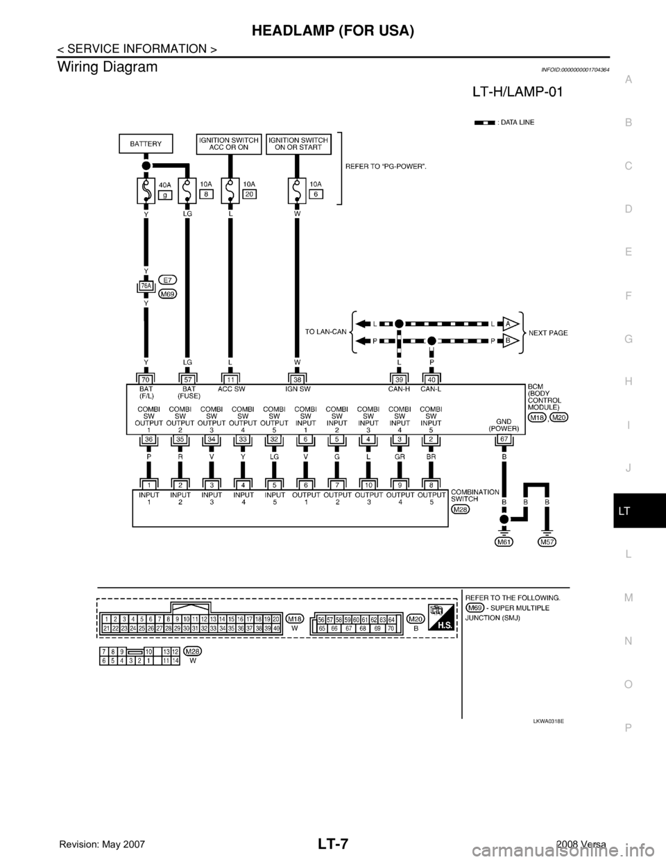
Wiring DiagramINFOID:0000000001704364
LKWA0318E
Page 2166 of 2771
HEADLAMP (FOR CANADA) - DAYTIME LIGHT SYSTEM -
LT-29
< SERVICE INFORMATION >
C
D
E
F
G
H
I
J
L
MA
B
LT
N
O
P
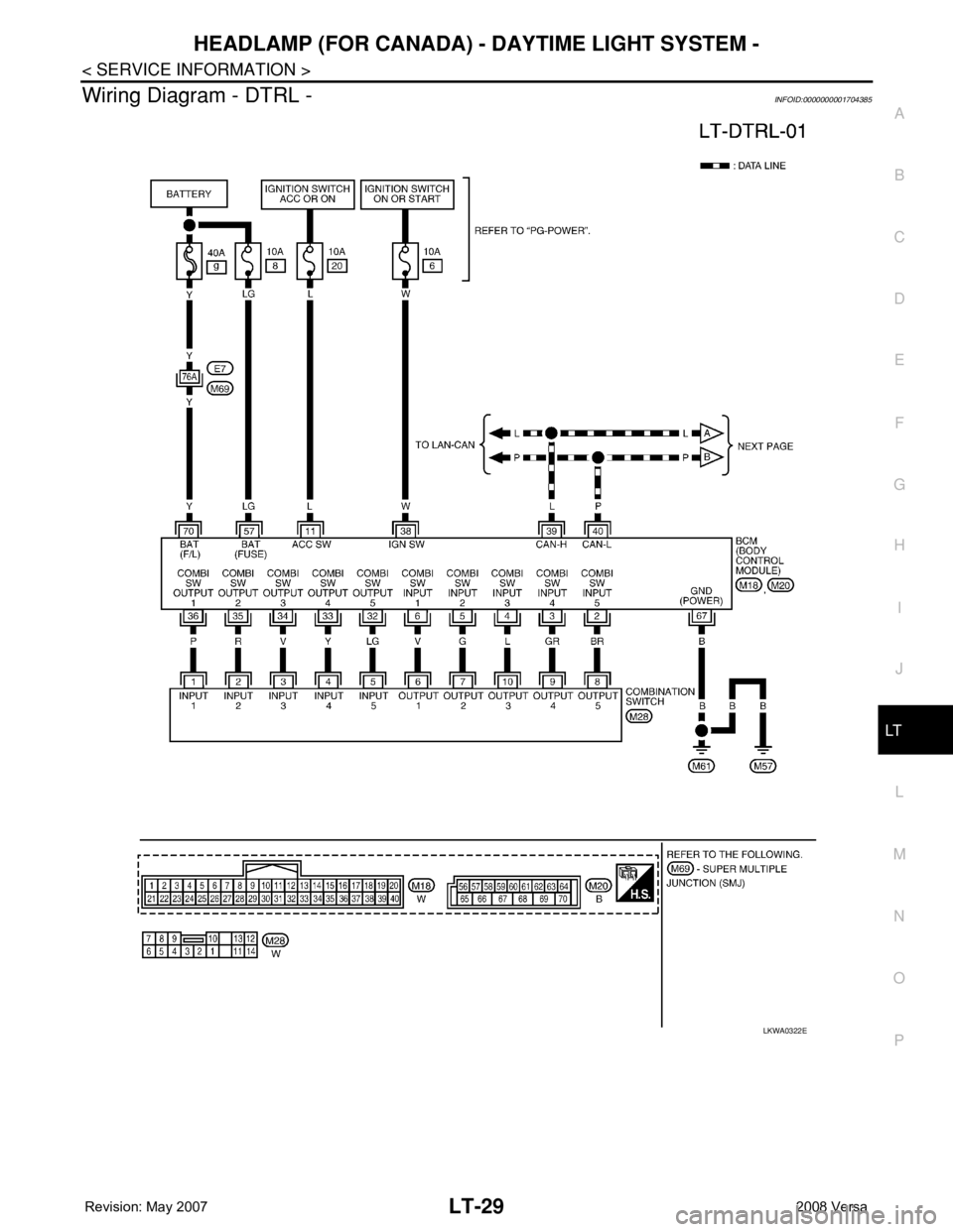
Wiring Diagram - DTRL -INFOID:0000000001704385
LKWA0322E
Page 2178 of 2771
FRONT FOG LAMP
LT-41
< SERVICE INFORMATION >
C
D
E
F
G
H
I
J
L
MA
B
LT
N
O
P
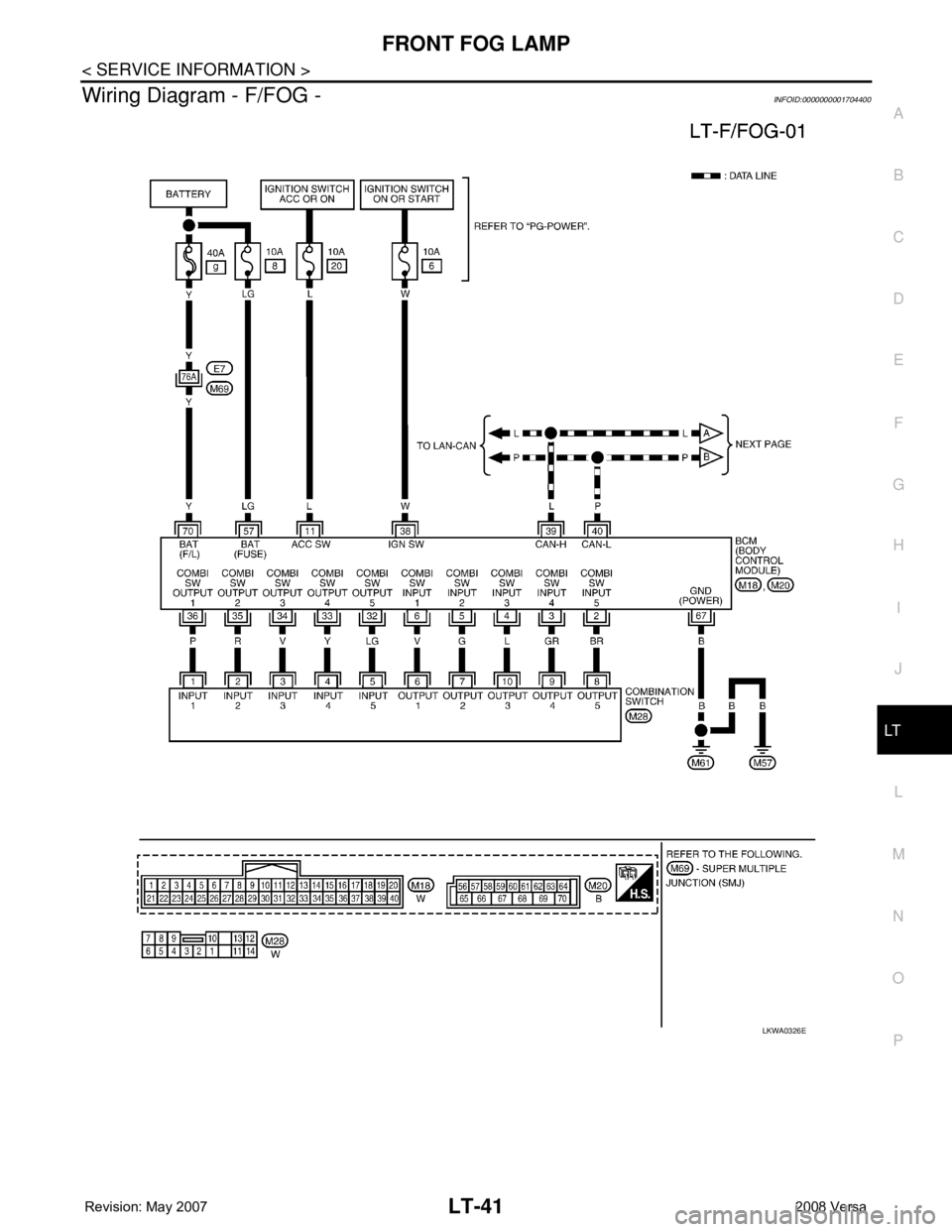
Wiring Diagram - F/FOG -INFOID:0000000001704400
LKWA0326E
Page 2189 of 2771
LT-52
< SERVICE INFORMATION >
TURN SIGNAL AND HAZARD WARNING LAMPS
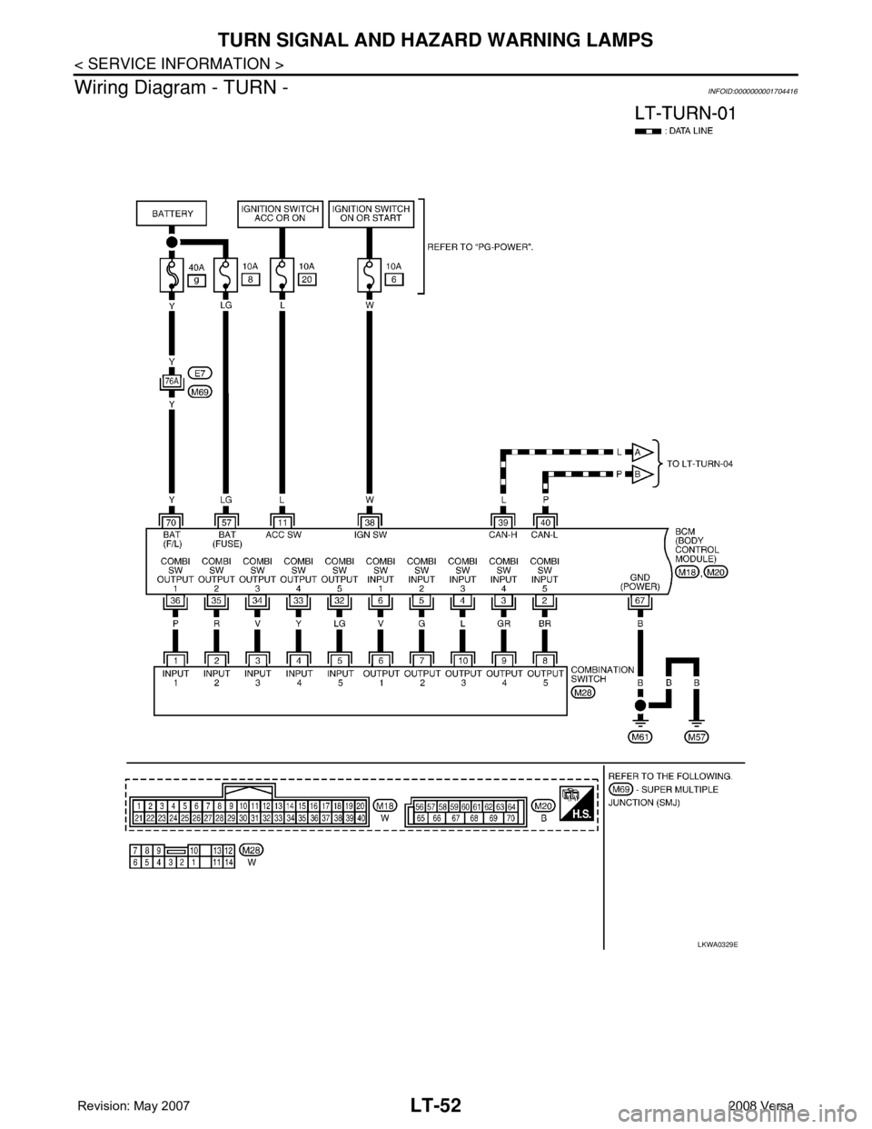
Wiring Diagram - TURN -
INFOID:0000000001704416
LKWA0329E