Page 2199 of 2771
LT-62
< SERVICE INFORMATION >
COMBINATION SWITCH
COMBINATION SWITCH
Wiring Diagram - COMBSW -INFOID:0000000001704432
Combination Switch Reading FunctionINFOID:0000000001704433
For details, refer to BCS-3, "System Description" .
LKWA0333E
Page 2203 of 2771
LT-66
< SERVICE INFORMATION >
STOP LAMP
STOP LAMP
Wiring Diagram - STOP/LINFOID:0000000001704438
HATCHBACK
WKWA5833E
Page 2204 of 2771
STOP LAMP
LT-67
< SERVICE INFORMATION >
C
D
E
F
G
H
I
J
L
MA
B
LT
N
O
P
Wiring Diagram - STOP/LINFOID:0000000001704439
SEDAN
Bulb Replacement for High-Mounted Stop LampINFOID:0000000001704440
HATCHBACK
The LED element is not serviced separately, the high-mounted stop lamp must be replaced as an assembly.
Refer to LT-68, "
Removal and Installation of High-Mounted Stop Lamp".
ALLWA0128GB
Page 2207 of 2771
LT-70
< SERVICE INFORMATION >
BACK-UP LAMP
BACK-UP LAMP
Wiring Diagram - BACK/L -INFOID:0000000001704444
Bulb ReplacementINFOID:0000000001704445
Refer to LT-85, "Bulb Replacement" .
WKWA5810E
Page 2212 of 2771
PARKING, LICENSE PLATE AND TAIL LAMPS
LT-75
< SERVICE INFORMATION >
C
D
E
F
G
H
I
J
L
MA
B
LT
N
O
P
Wiring Diagram - TAIL/L -INFOID:0000000001704451
LKWA0336E
Page 2231 of 2771
LT-94
< SERVICE INFORMATION >
INTERIOR ROOM LAMP
Wiring Diagram - INT/L -
INFOID:0000000001704471
WKWA5813E
Page 2245 of 2771
LT-108
< SERVICE INFORMATION >
ILLUMINATION
Wiring Diagram - ILL -
INFOID:0000000001704483
LKWA0344E
Page 2339 of 2771

MTC-1
AIR CONDITIONER
C
D
E
F
G
H
I
K
L
M
SECTION MTC
A
B
MTC
N
O
P
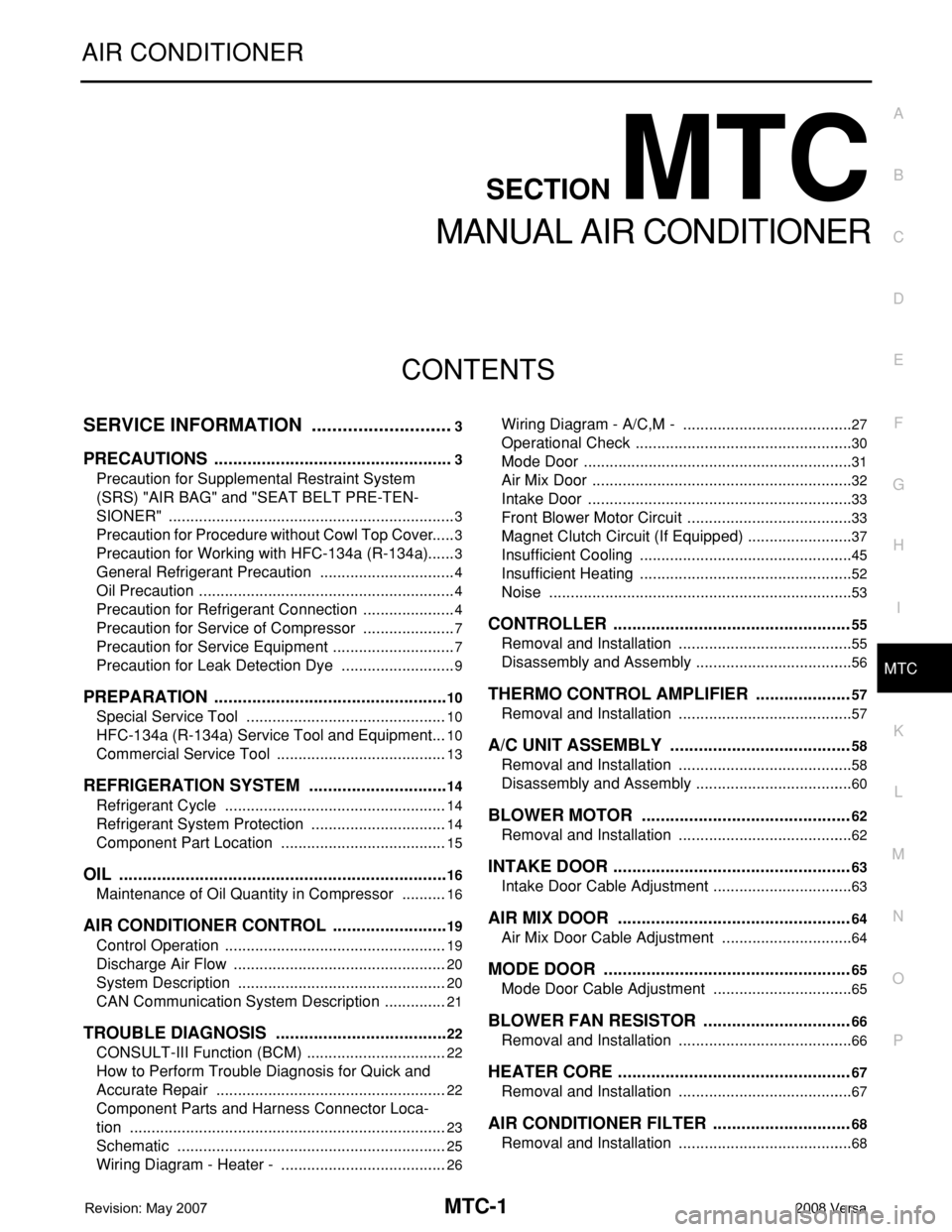
CONTENTS
MANUAL AIR CONDITIONER
SERVICE INFORMATION ............................3
PRECAUTIONS ...................................................3
Precaution for Supplemental Restraint System
(SRS) "AIR BAG" and "SEAT BELT PRE-TEN-
SIONER" ...................................................................
3
Precaution for Procedure without Cowl Top Cover ......3
Precaution for Working with HFC-134a (R-134a) ......3
General Refrigerant Precaution ................................4
Oil Precaution ............................................................4
Precaution for Refrigerant Connection ......................4
Precaution for Service of Compressor ......................7
Precaution for Service Equipment .............................7
Precaution for Leak Detection Dye ...........................9
PREPARATION ..................................................10
Special Service Tool ...............................................10
HFC-134a (R-134a) Service Tool and Equipment ....10
Commercial Service Tool ........................................13
REFRIGERATION SYSTEM ..............................14
Refrigerant Cycle ....................................................14
Refrigerant System Protection ................................14
Component Part Location .......................................15
OIL ......................................................................16
Maintenance of Oil Quantity in Compressor ...........16
AIR CONDITIONER CONTROL .........................19
Control Operation ....................................................19
Discharge Air Flow ..................................................20
System Description .................................................20
CAN Communication System Description ...............21
TROUBLE DIAGNOSIS .....................................22
CONSULT-III Function (BCM) .................................22
How to Perform Trouble Diagnosis for Quick and
Accurate Repair ......................................................
22
Component Parts and Harness Connector Loca-
tion ..........................................................................
23
Schematic ...............................................................25
Wiring Diagram - Heater - .......................................26
Wiring Diagram - A/C,M - ........................................27
Operational Check ...................................................30
Mode Door ...............................................................31
Air Mix Door .............................................................32
Intake Door ..............................................................33
Front Blower Motor Circuit .......................................33
Magnet Clutch Circuit (If Equipped) .........................37
Insufficient Cooling ..................................................45
Insufficient Heating ..................................................52
Noise .......................................................................53
CONTROLLER ..................................................55
Removal and Installation .........................................55
Disassembly and Assembly .....................................56
THERMO CONTROL AMPLIFIER ....................57
Removal and Installation .........................................57
A/C UNIT ASSEMBLY ......................................58
Removal and Installation .........................................58
Disassembly and Assembly .....................................60
BLOWER MOTOR ............................................62
Removal and Installation .........................................62
INTAKE DOOR ..................................................63
Intake Door Cable Adjustment .................................63
AIR MIX DOOR .................................................64
Air Mix Door Cable Adjustment ...............................64
MODE DOOR ....................................................65
Mode Door Cable Adjustment .................................65
BLOWER FAN RESISTOR ...............................66
Removal and Installation .........................................66
HEATER CORE .................................................67
Removal and Installation .........................................67
AIR CONDITIONER FILTER .............................68
Removal and Installation .........................................68