2008 NISSAN LATIO key fob
[x] Cancel search: key fobPage 505 of 2771

REMOTE KEYLESS ENTRY SYSTEM
BL-71
< SERVICE INFORMATION >
C
D
E
F
G
H
J
K
L
MA
B
BL
N
O
P
NG >> Repair or replace harness.
Keyfob Function (Lock) CheckINFOID:0000000001703993
1.CHECK KEYFOB FUNCTION
With CONSULT-III
Check keyfob function in “DATA MONITOR” mode with CONSULT-III. When pushing lock button of keyfob, the
corresponding monitor item should be turned as follows.
OK or NG
OK >> Keyfob is OK.
NG >> Replace keyfob.
Keyfob Function (Unlock) CheckINFOID:0000000001703994
1.CHECK KEYFOB FUNCTION
With CONSULT-III
Check keyfob function in “DATA MONITOR” mode with CONSULT-III. When pushing unlock button of keyfob,
the corresponding monitor item should be turned as follows.
OK or NG
OK >> Keyfob is OK.
NG >> Replace keyfob.
ID Code Entry ProcedureINFOID:0000000001703995
KEYFOB ID SET UP WITH CONSULT-III
NOTE:
•If a keyfob is lost, the ID code of the lost keyfob must be erased to prevent unauthorized use. A spe-
cific ID code can be erased with CONSULT-III. However, when the ID code of a lost keyfob is not
known, all controller ID codes should be erased. After all ID codes are erased, the ID codes of all
remaining and/or new keyfobs must be re-registered.
•When registering an additional keyfob, the existing ID codes in memory may or may not be erased. If
five ID codes are stored in memory, when an additional code is registered, only the oldest code is
erased. If less than five ID codes are stored in memory, when an additional ID code is registered, the
new ID code is added and no ID codes are erased.
•Entry of maximum five ID codes is allowed. When more than five ID codes are entered, the oldest ID
code will be erased.
•Even if same ID code that is already in the memory is input, the same ID code can be entered. The
code is counted as an additional code.
1. Touch “MULTI REMOTE ENT”.
2. Touch “WORK SUPPORT”.
3. The items are shown on the figure can be set up.
• “REMO CONT ID CONFIR”
Use this mode to confirm if a keyfob ID code is registered or not.
• “REMO CONT ID REGIST”
Use this mode to register a keyfob ID code.
NOTE:
Test item Condition
KEYLESS LOCKPushing LOCK button: ON
Other than above: OFF
Test item Condition
KEYLESS UNLOCKPushing UNLOCK button: ON
Other than above: OFF
Page 506 of 2771
BL-72
< SERVICE INFORMATION >
REMOTE KEYLESS ENTRY SYSTEM
Register the ID code when keyfob or BCM is replaced, or when additional keyfob is required.
• “REMO CONT ID ERASUR”
Use this mode to erase a keyfob ID code.
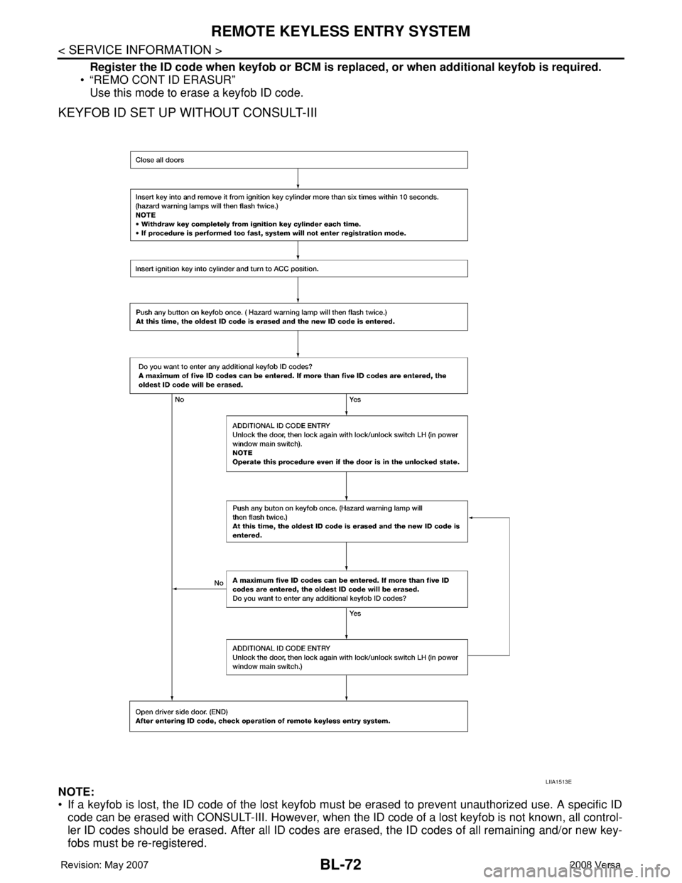
KEYFOB ID SET UP WITHOUT CONSULT-III
NOTE:
• If a keyfob is lost, the ID code of the lost keyfob must be erased to prevent unauthorized use. A specific ID
code can be erased with CONSULT-III. However, when the ID code of a lost keyfob is not known, all control-
ler ID codes should be erased. After all ID codes are erased, the ID codes of all remaining and/or new key-
fobs must be re-registered.
LIIA1513E
Page 507 of 2771
REMOTE KEYLESS ENTRY SYSTEM
BL-73
< SERVICE INFORMATION >
C
D
E
F
G
H
J
K
L
MA
B
BL
N
O
P
To erase all ID codes in memory, register one ID code (keyfob) five times. After all ID codes are erased, the
ID codes of all remaining and/or new keyfobs must be re-registered.
• When registering an additional keyfob, the existing ID codes in memory may or may not be erased. If five ID
codes are stored in memory, when an additional code is registered, only the oldest code is erased. If less
than five ID codes are stored in memory, when an additional ID code is registered, the new ID code is added
and no ID codes are erased.
• If you need to activate more than two additional new keyfobs, repeat the procedure “Additional ID code
entry” for each new keyfob.
• Entry of maximum five ID codes is allowed. When more than five ID codes are entered, the oldest ID code
will be erased.
• Even if same ID code that is already in the memory is input, the same ID code can be entered. The code is
counted as an additional code.
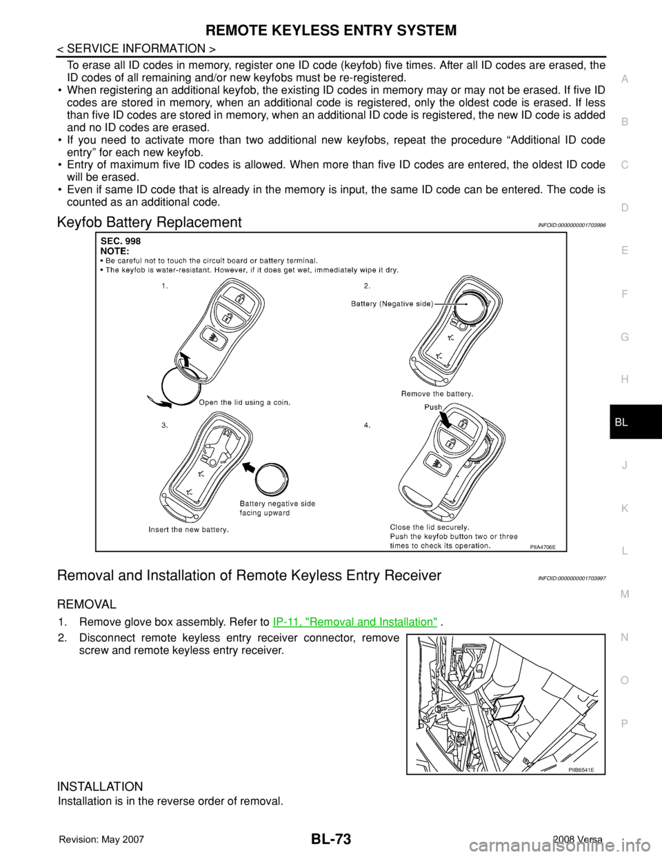
Keyfob Battery ReplacementINFOID:0000000001703996
Removal and Installation of Remote Keyless Entry ReceiverINFOID:0000000001703997
REMOVAL
1. Remove glove box assembly. Refer to IP-11, "Removal and Installation" .
2. Disconnect remote keyless entry receiver connector, remove
screw and remote keyless entry receiver.
INSTALLATION
Installation is in the reverse order of removal.
PIIA4706E
PIIB6541E
Page 512 of 2771

BL-78
< SERVICE INFORMATION >
INTELLIGENT KEY SYSTEM
* : Hatchback
** : Sedan
KEY REMINDER FUNCTION
Key reminder functions have the following 2 functions.
CAUTION:
• The above function operates when the Intelligent Key is inside the vehicle. However, there may be
times when the Intelligent Key cannot be detected, and this function will not operate when the Intelli-
gent Key is on the instrument panel, rear parcel shelf or in the glove box. Also, this system some-
times does not operate if the Intelligent Key is in the door pocket of an open door.
List of Operation Related Parts
Parts marked with × are the parts related to operation
REMOTE KEYLESS ENTRY FUNCTIONS
The Intelligent Key has the same functions as the remote keyless entry system. Therefore, it can be used in
the same manner as the keyfob by operating the door lock/unlock button.
Door lock open function
Intelligent Key
Key switch
Ignition knob switch
Door switch
Back door lock assembly (back door switch)
*
Request switch (driver, passenger, back)
Door lock actuator
Inside key antenna
Outside key antenna
Intelligent Key warning buzzer (front door LH)
Intelligent Key warning buzzer (trunk)
**
Intelligent Key unit
CAN communication system
BCM
Hazard warning lamp
Door lock/unlock function by request switch××××××××××
Door lock/unlock function by mechanical key××
Hazard and buzzer reminder function××××××
Auto door lock function×××× × ×××
Key reminder function Operation condition Operation
Door is open to closeRight after all doors are closed under the following conditions.
• Intelligent Key is inside the vehicle
• Any door is opened
• All doors are locked by door lock and unlock switch or door
lock knob• All doors unlock operation
• Sound Intelligent Key warn-
ing buzzer for 3 seconds
Key reminder functions
Intelligent Key
Door switch
Unlock sensor
Door lock actuator
Inside key antenna
Intelligent Key warning buzzer(s)
Intelligent Key unit
CAN communication system
BCM
Any door open to close×××××××××
Page 536 of 2771

BL-102
< SERVICE INFORMATION >
INTELLIGENT KEY SYSTEM
* : Sedan
WORK SUPPORT
Te s t i t e m D e s c r i p t i o n
DOOR LOCK/UNLOCKThis test is able to check door lock/unlock operation.
• The all door lock actuators are unlocked when “ALL UNLK” on CONSULT-III screen is touched.
• The all door lock actuators are locked when “LOCK” on CONSULT-III screen is touched.
ANTENNAThis test is able to check Intelligent Key antenna operation.
When the following conditions are met, hazard warning lamps flash.
• Inside key antenna (front console) detects Intelligent Key, when “ROOM ANT1” on CONSULT-
III screen is touched.
• Inside key antenna (instrument panel and rear floor) detects Intelligent Key, when “ROOM
ANT2” on CONSULT-III screen is touched.
• Outside key antenna (driver side) detects Intelligent Key, when “DRIVER ANT” on CONSULT-III
screen is touched.
• Outside key antenna (passenger side) detects Intelligent Key, when “ASSIST ANT” on CON-
SULT-III screen is touched.
• Outside key antenna (rear bumper) detects Intelligent Key, when “BK DOOR ANT” on CON-
SULT-III screen is touched.
OUTSIDE BUZZER(S)
(DRIVER DOOR), (TRUNK)
*This test is able to check Intelligent Key warning buzzer operation.
Intelligent Key warning buzzer sounds when “ON” on CONSULT-III screen is touched.
INSIDE BUZZER
(CHIME)This test is able to check Intelligent Key warning chime (Instrument panel) operation.
• Take away warning chime sounds when “TAKE OUT” on CONSULT-III screen is touched.
• Ignition switch warning chime sounds when “KNOB” on CONSULT-III screen is touched.
• Ignition key warning chime sounds when “KEY” on CONSULT-III screen is touched.
INDICATORThis test is able to check warning lamp operation.
• “KEY” Warning lamp (Green) illuminates when “BLUE ON” on CONSULT-III screen is touched.
• “KEY” Warning lamp (Red) illuminates when “RED ON” on CONSULT-III screen is touched.
• “LOCK” Warning lamp illuminates when “KNOB ON” on CONSULT-III screen is touched.
• “KEY” Warning lamp (Green) flashes when “BLUE IND” on CONSULT-III screen is touched.
• “KEY” Warning lamp (RED) flashes when “BLUE IND” on CONSULT-III screen is touched.
• “P-SHIFT” Warning lamp flashes when “KNOB ON” on CONSULT-III screen is touched.
Monitor item Description
CONFIRM KEY FOB ID It can be checked whether Intelligent Key ID code is registered or not in this mode.
TAKE OUT FROM WINDOW
WARNTake away warning chime (from window) mode can be changed to operate (ON) or not operate
(OFF) with this mode. The operation mode will be changed when “CHANGE SETT” on CONSULT-
III screen is touched.
LOW BAT OF KEY FOB WARNIntelligent Key low battery warning mode can be changed to operate (ON) or not operate (OFF)
with this mode. The operation mode will be changed when “CHANGE SETT” on CONSULT-III
screen is touched.
ANSWER BACK FUNCTIONBuzzer reminder function mode by Intelligent button can be changed to operate (ON) or not oper-
ate (OFF) with this mode. The operation mode will be changed when “CHANGE SETT” on CON-
SULT-III screen is touched.
SELECTIVE UNLOCK FUNC-
TIONSelective unlock function mode can be changed to operate (ON) or not operate (OFF) with this
mode. The operation mode will be changed when “CHANGE SETT” on CONSULT-III screen is
touched.
ANTI KEY LOCK IN FUNCTIONKey reminder function mode can be changed to operate (ON) or not operate (OFF) with this mode.
The operation mode will be changed when “CHANGE SETT” on CONSULT-III screen is touched.
HORN WITH KEYLESS LOCKHorn reminder function mode by Intelligent Key remote control button can be changed to operate
(ON) or not operate (OFF) with this mode. The operation mode will be changed when “CHANGE
SETT” on CONSULT-III screen is touched.
HAZARD ANSWER BACKHazard reminder function mode can be selected from the following with this mode. The operation
mode will be changed when “CHANGE SETT” on CONSULT-III screen is touched.
• LOCK ONLY: Door lock operation only
• UNLOCK ONLY: Door unlock operation only
• LOCK/UNLOCK: Lock/Unlock operation
• OFF: Non-operation
Page 538 of 2771
BL-104
< SERVICE INFORMATION >
INTELLIGENT KEY SYSTEM
• Key is not inserted in ignition switch.
• One or more registered Intelligent Keys are in the vehicle.
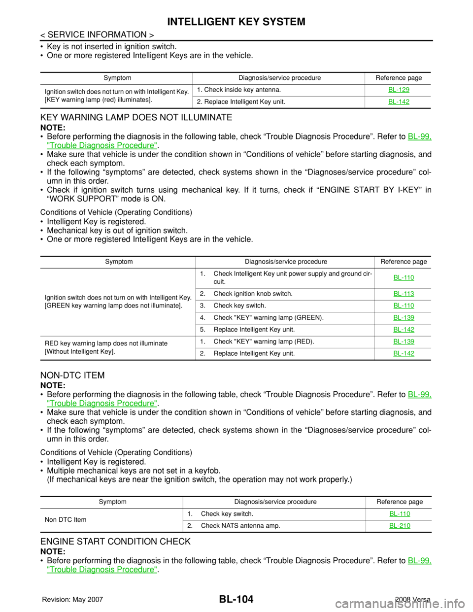
KEY WARNING LAMP DOES NOT ILLUMINATE
NOTE:
• Before performing the diagnosis in the following table, check “Trouble Diagnosis Procedure”. Refer to BL-99,
"Trouble Diagnosis Procedure".
• Make sure that vehicle is under the condition shown in “Conditions of vehicle” before starting diagnosis, and
check each symptom.
• If the following “symptoms” are detected, check systems shown in the “Diagnoses/service procedure” col-
umn in this order.
• Check if ignition switch turns using mechanical key. If it turns, check if “ENGINE START BY I-KEY” in
“WORK SUPPORT” mode is ON.
Conditions of Vehicle (Operating Conditions)
• Intelligent Key is registered.
• Mechanical key is out of ignition switch.
• One or more registered Intelligent Keys are in the vehicle.
NON-DTC ITEM
NOTE:
• Before performing the diagnosis in the following table, check “Trouble Diagnosis Procedure”. Refer to BL-99,
"Trouble Diagnosis Procedure".
• Make sure that vehicle is under the condition shown in “Conditions of vehicle” before starting diagnosis, and
check each symptom.
• If the following “symptoms” are detected, check systems shown in the “Diagnoses/service procedure” col-
umn in this order.
Conditions of Vehicle (Operating Conditions)
• Intelligent Key is registered.
• Multiple mechanical keys are not set in a keyfob.
(If mechanical keys are near the ignition switch, the operation may not work properly.)
ENGINE START CONDITION CHECK
NOTE:
• Before performing the diagnosis in the following table, check “Trouble Diagnosis Procedure”. Refer to BL-99,
"Trouble Diagnosis Procedure".
Symptom Diagnosis/service procedure Reference page
Ignition switch does not turn on with Intelligent Key.
[KEY warning lamp (red) illuminates].1. Check inside key antenna.BL-129
2. Replace Intelligent Key unit.BL-142
Symptom Diagnosis/service procedure Reference page
Ignition switch does not turn on with Intelligent Key.
[GREEN key warning lamp does not illuminate].1. Check Intelligent Key unit power supply and ground cir-
cuit.BL-110
2. Check ignition knob switch.BL-113
3. Check key switch.BL-110
4. Check "KEY" warning lamp (GREEN).BL-139
5. Replace Intelligent Key unit.BL-142
RED key warning lamp does not illuminate
[Without Intelligent Key].1. Check "KEY" warning lamp (RED).BL-139
2. Replace Intelligent Key unit.BL-142
Symptom Diagnosis/service procedure Reference page
Non DTC Item1. Check key switch.BL-110
2. Check NATS antenna amp.BL-210
Page 543 of 2771
INTELLIGENT KEY SYSTEM
BL-109
< SERVICE INFORMATION >
C
D
E
F
G
H
J
K
L
MA
B
BL
N
O
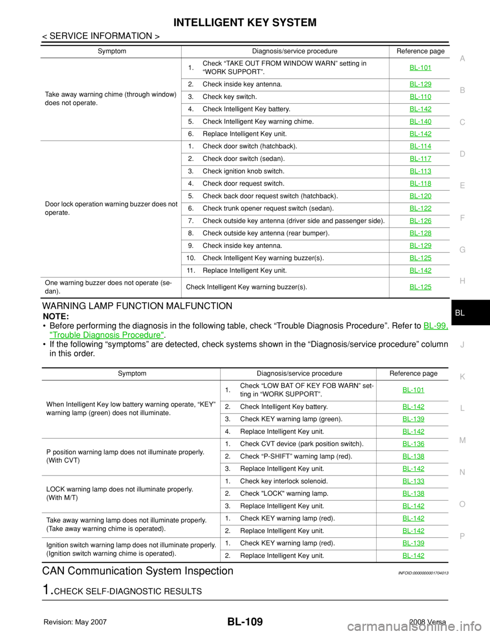
PWARNING LAMP FUNCTION MALFUNCTION
NOTE:
• Before performing the diagnosis in the following table, check “Trouble Diagnosis Procedure”. Refer to BL-99,
"Trouble Diagnosis Procedure".
• If the following “symptoms” are detected, check systems shown in the “Diagnosis/service procedure” column
in this order.
CAN Communication System InspectionINFOID:0000000001704013
1.CHECK SELF-DIAGNOSTIC RESULTS
Take away warning chime (through window)
does not operate.1.Check “TAKE OUT FROM WINDOW WARN” setting in
“WORK SUPPORT”.BL-101
2. Check inside key antenna.BL-129
3. Check key switch.BL-110
4. Check Intelligent Key battery.BL-142
5. Check Intelligent Key warning chime.BL-140
6. Replace Intelligent Key unit.BL-142
Door lock operation warning buzzer does not
operate.1. Check door switch (hatchback).BL-114
2. Check door switch (sedan).BL-117
3. Check ignition knob switch.BL-113
4. Check door request switch.BL-118
5. Check back door request switch (hatchback).BL-120
6. Check trunk opener request switch (sedan).BL-122
7. Check outside key antenna (driver side and passenger side).BL-126
8. Check outside key antenna (rear bumper).BL-128
9. Check inside key antenna.BL-129
10. Check Intelligent Key warning buzzer(s).BL-125
11. Replace Intelligent Key unit.BL-142
One warning buzzer does not operate (se-
dan).Check Intelligent Key warning buzzer(s).BL-125
Symptom Diagnosis/service procedure Reference page
Symptom Diagnosis/service procedure Reference page
When Intelligent Key low battery warning operate, “KEY”
warning lamp (green) does not illuminate.1.Check “LOW BAT OF KEY FOB WARN” set-
ting in “WORK SUPPORT”.BL-101
2. Check Intelligent Key battery.BL-142
3. Check KEY warning lamp (green).BL-139
4. Replace Intelligent Key unit.BL-142
P position warning lamp does not illuminate properly.
(With CVT)1. Check CVT device (park position switch).BL-1362. Check “P-SHIFT” warning lamp (red).BL-138
3. Replace Intelligent Key unit.BL-142
LOCK warning lamp does not illuminate properly.
(With M/T)1. Check key interlock solenoid.BL-1332. Check "LOCK" warning lamp.BL-138
3. Replace Intelligent Key unit.BL-142
Take away warning lamp does not illuminate properly.
(Take away warning chime is operated).1. Check KEY warning lamp (red).BL-142
2. Replace Intelligent Key unit.BL-142
Ignition switch warning lamp does not illuminate properly.
(Ignition switch warning chime is operated).1. Check KEY warning lamp (red).BL-139
2. Replace Intelligent Key unit.BL-142
Page 576 of 2771
BL-142
< SERVICE INFORMATION >
INTELLIGENT KEY SYSTEM
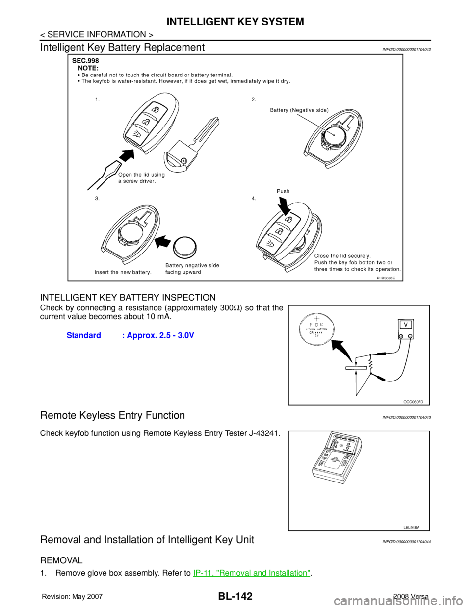
Intelligent Key Battery Replacement
INFOID:0000000001704042
INTELLIGENT KEY BATTERY INSPECTION
Check by connecting a resistance (approximately 300Ω) so that the
current value becomes about 10 mA.
Remote Keyless Entry FunctionINFOID:0000000001704043
Check keyfob function using Remote Keyless Entry Tester J-43241.
Removal and Installation of Intelligent Key UnitINFOID:0000000001704044
REMOVAL
1. Remove glove box assembly. Refer to IP-11, "Removal and Installation".
PIIB5065E
Standard : Approx. 2.5 - 3.0V
OCC0607D
LEL946A