Page 2599 of 2771

STARTING SYSTEM
SC-17
< SERVICE INFORMATION >
C
D
E
F
G
H
I
J
L
MA
B
SC
N
O
P
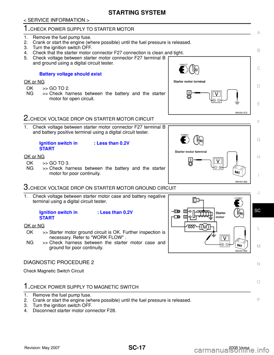
1.CHECK POWER SUPPLY TO STARTER MOTOR
1. Remove the fuel pump fuse.
2. Crank or start the engine (where possible) until the fuel pressure is released.
3. Turn the ignition switch OFF.
4. Check that the starter motor connector F27 connection is clean and tight.
5. Check voltage between starter motor connector F27 terminal B
and ground using a digital circuit tester.
OK or NG
OK >> GO TO 2.
NG >> Check harness between the battery and the starter
motor for open circuit.
2.CHECK VOLTAGE DROP ON STARTER MOTOR CIRCUIT
1. Check voltage between starter motor connector F27 terminal B
and battery positive terminal using a digital circuit tester.
OK or NG
OK >> GO TO 3.
NG >> Check harness between the battery and the starter
motor for poor continuity.
3.CHECK VOLTAGE DROP ON STARTER MOTOR GROUND CIRCUIT
1. Check voltage between starter motor case and battery negative
terminal using a digital circuit tester.
OK or NG
OK >> Starter motor ground circuit is OK. Further inspection is
necessary. Refer to "WORK FLOW" .
NG >> Check harness between the starter motor case and
ground for poor continuity.
DIAGNOSTIC PROCEDURE 2
Check Magnetic Switch Circuit
1.CHECK POWER SUPPLY TO MAGNETIC SWITCH
1. Remove the fuel pump fuse.
2. Crank or start the engine (where possible) until the fuel pressure is released.
3. Turn the ignition switch OFF.
4. Disconnect starter motor connector F28.Battery voltage should exist
WKIA0137E
Ignition switch in
START: Less than 0.2V
WKIA0138E
Ignition switch in
START: Less than 0.2V
WKIA0139E
Page 2600 of 2771

SC-18
< SERVICE INFORMATION >
STARTING SYSTEM
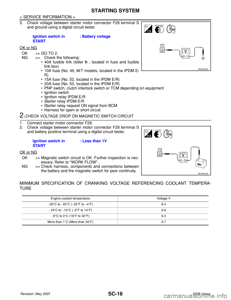
5. Check voltage between starter motor connector F28 terminal S
and ground using a digital circuit tester.
OK or NG
OK >> GO TO 2.
NG >> Check the following:
• 40A fusible link (letter h , located in fuse and fusible
link box)
• 10A fuse (No. 49, M/T models, located in the IPDM E/
R)
• 15A fuse (No. 52, located in the IPDM E/R)
• 20A fuse (No. 53, located in the IPDM E/R)
• PNP switch, clutch interlock switch or TCM depending on equipment
• Ignition switch
• Ignition relay IPDM E/R
• Starter relay IPDM E/R
• Starter relay request ON signal from BCM
• Harness for open or short circuit
2.CHECK VOLTAGE DROP ON MAGNETIC SWITCH CIRCUIT
1. Connect starter motor connector F28.
2. Check voltage between starter motor connector F28 terminal S
and battery positive terminal using a digital circuit tester.
OK or NG
OK >> Magnetic switch circuit is OK. Further inspection is nec-
essary. Refer to "WORK FLOW" .
NG >> Check harness, components and connections between
the battery and the magnetic switch for poor continuity.
MINIMUM SPECIFICATION OF CRANKING VOLTAGE REFERENCING COOLANT TEMPERA-
TURE
Ignition switch in
START: Battery voltage
WKIA5243E
Ignition switch in
START: Less than 1V
WKIA5244E
Engine coolant temperature Voltage V
−30°C to −20°C (−22°F to −4°F) 8.4
−19°C to −10°C (−2°F to 14°F) 8.9
−9°C to 0°C (16°F to 32°F) 9.3
More than 1°C (More than 34°F) 9.7
Page 2601 of 2771
STARTING SYSTEM
SC-19
< SERVICE INFORMATION >
C
D
E
F
G
H
I
J
L
MA
B
SC
N
O
P
Removal and InstallationINFOID:0000000001704351
REMOVAL
1. Disconnect the battery negative terminal.
2. Remove air duct (inlet). Refer to EM-16
.
3. Remove reservoir tank. Refer to CO-11
.
4. Remove “S” terminal nut.
5. Remove “B” terminal nut.
6. Remove starter motor bolts.
7. Remove starter motor.
INSTALLATION
Installation is in the reverse order of removal.
CAUTION:
Be sure to tighten “B” terminal nut carefully.
1. "S" terminal harness 2. "B" terminal harness 3. Starter motor
4. Cylinder block Engine front
WKIA5611E
Page 2602 of 2771

SC-20
< SERVICE INFORMATION >
CHARGING SYSTEM
CHARGING SYSTEM
System DescriptionINFOID:0000000001704352
The generator provides DC voltage to operate the vehicle's electrical system and to keep the battery charged.
The voltage output is controlled by the IC regulator.
Power is supplied at all times to generator terminal 3 through
• 10A fuse (No. 29, located in the fuse and fusible link box).
Power is supplied through terminal 1 to charge the battery and operate the vehicle's electrical system. Output
voltage is monitored at terminal 3 by the IC regulator. The charging circuit is protected by the 120A fusible link
[letter a , located in the fusible link box (battery)].
Ground is supplied
• to generator terminal 5
• through body ground F5, and
• through the generator case to the cylinder block
With the ignition switch in the ON or START position, power is supplied
• through 10A fuse [No. 3, located in the fuse block (J/B)]
• to combination meter terminal 28 for the charge warning lamp.
The IC regulator controls ground to terminal 38 of the combination meter through terminal 2 of the generator.
When the ignition is turned on and power becomes available at terminal 2, this "wakes up" the regulator. The
regulator monitors charge output and grounds terminal 2 or leaves it open depending on charge output. With
power and ground supplied, the charge warning lamp will illuminate. When the generator is providing sufficient
voltage, the ground is opened and the charge warning lamp will go off.
If the charge warning lamp illuminates with the engine running, a malfunction is indicated.
Page 2603 of 2771
CHARGING SYSTEM
SC-21
< SERVICE INFORMATION >
C
D
E
F
G
H
I
J
L
MA
B
SC
N
O
P
Wiring Diagram - CHARGE -INFOID:0000000001704353
Trouble Diagnosis with Starting/Charging System TesterINFOID:0000000001704354
For charging system testing, use Starting/Charging System Tester (J-44373). For details, refer to Technical
Service Bulletin.
WKWA4970E
Page 2604 of 2771
SC-22
< SERVICE INFORMATION >
CHARGING SYSTEM
WORK FLOW
DIAGNOSTIC PROCEDURE 1
Check Charge Warning Lamp Circuit
1.CHECK CHARGE WARNING LAMP CIRCUIT CONNECTION
Check to see if terminal 2 is clean and tight.
OK or NG
OK >> GO TO 2.
NG >> Repair terminal 2 connection. Confirm repair by performing complete Starting/Charging system
test. Refer to Technical Service Bulletin.
WKIA4022E
Page 2605 of 2771

CHARGING SYSTEM
SC-23
< SERVICE INFORMATION >
C
D
E
F
G
H
I
J
L
MA
B
SC
N
O
P
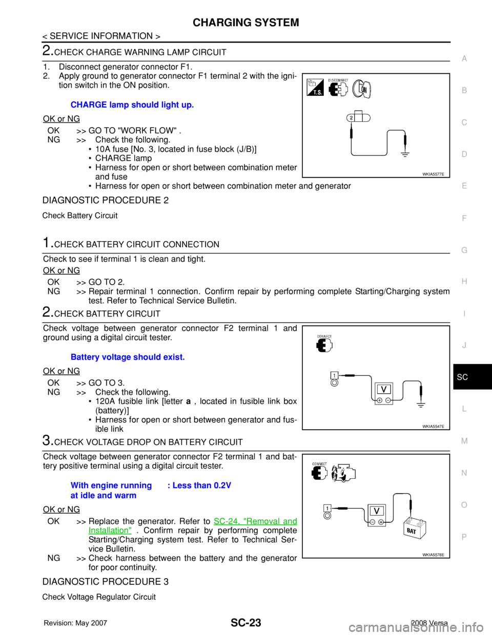
2.CHECK CHARGE WARNING LAMP CIRCUIT
1. Disconnect generator connector F1.
2. Apply ground to generator connector F1 terminal 2 with the igni-
tion switch in the ON position.
OK or NG
OK >> GO TO "WORK FLOW" .
NG >> Check the following.
• 10A fuse [No. 3, located in fuse block (J/B)]
• CHARGE lamp
• Harness for open or short between combination meter
and fuse
• Harness for open or short between combination meter and generator
DIAGNOSTIC PROCEDURE 2
Check Battery Circuit
1.CHECK BATTERY CIRCUIT CONNECTION
Check to see if terminal 1 is clean and tight.
OK or NG
OK >> GO TO 2.
NG >> Repair terminal 1 connection. Confirm repair by performing complete Starting/Charging system
test. Refer to Technical Service Bulletin.
2.CHECK BATTERY CIRCUIT
Check voltage between generator connector F2 terminal 1 and
ground using a digital circuit tester.
OK or NG
OK >> GO TO 3.
NG >> Check the following.
• 120A fusible link [letter a , located in fusible link box
(battery)]
• Harness for open or short between generator and fus-
ible link
3.CHECK VOLTAGE DROP ON BATTERY CIRCUIT
Check voltage between generator connector F2 terminal 1 and bat-
tery positive terminal using a digital circuit tester.
OK or NG
OK >> Replace the generator. Refer to SC-24, "Removal and
Installation" . Confirm repair by performing complete
Starting/Charging system test. Refer to Technical Ser-
vice Bulletin.
NG >> Check harness between the battery and the generator
for poor continuity.
DIAGNOSTIC PROCEDURE 3
Check Voltage Regulator Circuit
CHARGE lamp should light up.
WKIA5577E
Battery voltage should exist.
WKIA5547E
With engine running
at idle and warm: Less than 0.2V
WKIA5578E
Page 2606 of 2771

SC-24
< SERVICE INFORMATION >
CHARGING SYSTEM
1.CHECK VOLTAGE REGULATOR CIRCUIT CONNECTION
Check to see if terminal 3 is clean and tight.
OK or NG
OK >> GO TO 2.
NG >> Repair terminal 3 connection. Confirm repair by performing complete Starting/Charging system
test. Refer to Technical Service Bulletin.
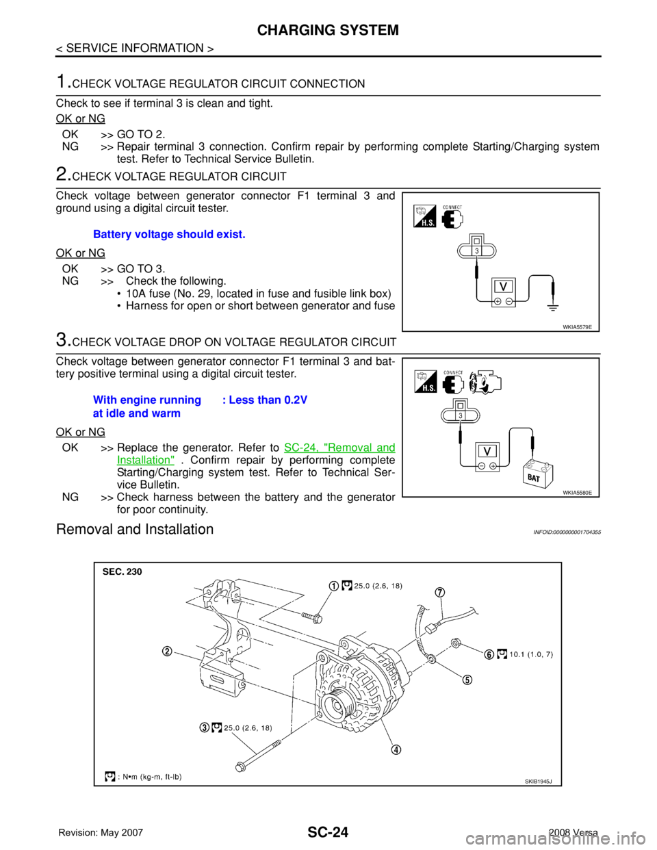
2.CHECK VOLTAGE REGULATOR CIRCUIT
Check voltage between generator connector F1 terminal 3 and
ground using a digital circuit tester.
OK or NG
OK >> GO TO 3.
NG >> Check the following.
• 10A fuse (No. 29, located in fuse and fusible link box)
• Harness for open or short between generator and fuse
3.CHECK VOLTAGE DROP ON VOLTAGE REGULATOR CIRCUIT
Check voltage between generator connector F1 terminal 3 and bat-
tery positive terminal using a digital circuit tester.
OK or NG
OK >> Replace the generator. Refer to SC-24, "Removal and
Installation" . Confirm repair by performing complete
Starting/Charging system test. Refer to Technical Ser-
vice Bulletin.
NG >> Check harness between the battery and the generator
for poor continuity.
Removal and InstallationINFOID:0000000001704355
Battery voltage should exist.
WKIA5579E
With engine running
at idle and warm: Less than 0.2V
WKIA5580E
SKIB1945J