Page 2407 of 2771
DUCTS AND GRILLES
MTC-69
< SERVICE INFORMATION >
C
D
E
F
G
H
I
K
L
MA
B
MTC
N
O
P
DUCTS AND GRILLES
Removal and InstallationINFOID:0000000001704321
Floor Ducts - Canada Only
1. Side defroster duct (right) 2. Defroster nozzle 3. Side defroster duct (left)
4. Side defroster grille (left) 5. Instrument side panel (left) 6. Instrument panel and pad
7. Side ventilator assembly (left) 8. Cluster lid C 9. Side ventilator assembly (right)
10. Instrument finisher E 11. Instrument side panel (right) 12. Side defroster grille (right)
13. Side ventilator duct (right) 14. Center ventilator duct (right) 15. Center ventilator duct (left)
16. Side ventilator duct (left)
SJIA0657E
WJIA2198E
Page 2408 of 2771
MTC-70
< SERVICE INFORMATION >
DUCTS AND GRILLES
CENTER VENTILATOR GRILLES
Removal
1. Remove cluster lid C. Refer to IP-10.
2. Remove center ventilator grills (1) from cluster lid C using suit-
able tool (A).
Installation
Installation is in the reverse order of removal.
SIDE VENTILATOR GRILLES (LH/RH)
Removal
1. Remove side ventilator assembly (LH). Refer to IP-10.
2. Remove side ventilator grille (LH) (1) using suitable tool (A).
3. Remove side ventilator assembly (RH). Refer to IP-10
.
4. Remove side ventilator grille (RH) (1) using suitable tool (A).
Installation
Installation is in the reverse order of removal.
DEFROSTER NOZZLE AND SIDE DEFROSTER DUCTS (LH/RH)
1. Front floor duct 2. Rear floor duct (left) 3. Clip
4. Rear floor duct (right)
ZJIA0661E
SJIA0658E
SJIA0659E
Page 2409 of 2771
DUCTS AND GRILLES
MTC-71
< SERVICE INFORMATION >
C
D
E
F
G
H
I
K
L
MA
B
MTC
N
O
P Removal
1. Remove instrument upper finisher. Refer to IP-10.
2. Remove screws and then remove side defroster duct (RH) and side defroster duct (LH).
3. Remove screws, and then remove defroster nozzle.
Installation
Installation is in the reverse order of removal.
SIDE VENTILATOR DUCTS
Removal
1. Remove instrument panel and pad. Refer to IP-10.
2. Remove screws (A), and then remove side ventilator duct (left)
(1).
3. Remove screw (A) and clip (B), and then remove side ventilator
duct (right) (1).
Installation
Installation is in the reverse order of removal.
1. Side defroster duct (RH) 2. Side defroster duct (LH) 3. Defroster nozzle
A. Side defroster duct screw B. Defroster nozzle screw
WJIA2199E
SJIA0661E
SJIA0662E
Page 2410 of 2771
MTC-72
< SERVICE INFORMATION >
DUCTS AND GRILLES
CENTER VENTILATOR DUCTS
Removal
1. Remove instrument panel & pad. Refer to IP-10.
2. Remove screws (A), and then remove center ventilator ducts
(1).
Installation
Installation is in the reverse order of removal.
SIDE FOOT DUCTS
NOTE:
The side foot ducts are part of the A/C unit assembly case.
Removal
1. Remove A/C unit assembly. Refer to MTC-58.
2. Remove screws (A), and then remove side foot duct (LH) (1).
3. Remove screws (A), and then remove side foot duct (RH) (1).
Installation
Installation is in the reverse order of removal.
FLOOR DUCTS
Removal
1. Remove front seats and center console assembly. Refer to SE-10 and IP-10.
SJIA0663E
SJIA0664E
SJIA0665E
Page 2411 of 2771
DUCTS AND GRILLES
MTC-73
< SERVICE INFORMATION >
C
D
E
F
G
H
I
K
L
MA
B
MTC
N
O
P
2. Disengage claws (A), and then remove front floor duct (1).
3. Peel back floor trim to a point where floor duct is visible.
4. Remove clips (A), and then remove rear floor duct (left) (1) and
rear floor duct (right) (2).
Installation
Installation is in the reverse order of removal.
SJIA0667E
SJIA0668E
Page 2412 of 2771

MTC-74
< SERVICE INFORMATION >
REFRIGERANT LINES
REFRIGERANT LINES
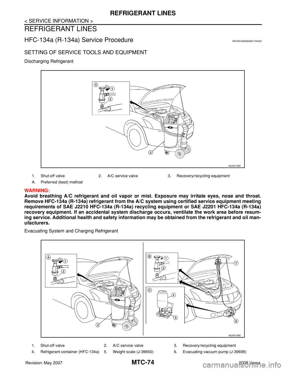
HFC-134a (R-134a) Service ProcedureINFOID:0000000001704322
SETTING OF SERVICE TOOLS AND EQUIPMENT
Discharging Refrigerant
WARNING:
Avoid breathing A/C refrigerant and oil vapor or mist. Exposure may irritate eyes, nose and throat.
Remove HFC-134a (R-134a) refrigerant from the A/C system using certified service equipment meeting
requirements of SAE J2210 HFC-134a (R-134a) recycling equipment or SAE J2201 HFC-134a (R-134a)
recovery equipment. If an accidental system discharge occurs, ventilate the work area before resum-
ing service. Additional health and safety information may be obtained from the refrigerant and oil man-
ufacturers.
Evacuating System and Charging Refrigerant
1. Shut-off valve 2. A/C service valve 3. Recovery/recycling equipment
A. Preferred (best) method
WJIA2195E
1. Shut-off valve 2. A/C service valve 3. Recovery/recycling equipment
4. Refrigerant container (HFC-134a) 5. Weight scale (J-39650) 6. Evacuating vacuum pump (J-39699)
WJIA2196E
Page 2413 of 2771
REFRIGERANT LINES
MTC-75
< SERVICE INFORMATION >
C
D
E
F
G
H
I
K
L
MA
B
MTC
N
O
P
7. Manifold gauge set (J-39183) A. Preferred (best) method B. Alternative method
C. For charging
*1MTC-16, "
Maintenance of Oil Quanti-
ty in Compressor"
*2MTC-84, "Checking of Refrigerant
Leaks"
*3MTC-85, "Electronic Refrigerant
Leak Detector"
*4MTC-45, "Insufficient Cooling"
WJIA1923E
Page 2414 of 2771
MTC-76
< SERVICE INFORMATION >
REFRIGERANT LINES
Component
INFOID:0000000001704323
Type 1 A/C System
WJIA2200E
1. Evaporator 2. Expansion valve 3. Low-pressure service valve
4. High-pressure service valve 5. Refrigerant pressure sensor 6. Shaft seal
7. Drain hose