Page 2399 of 2771
A/C UNIT ASSEMBLY
MTC-61
< SERVICE INFORMATION >
C
D
E
F
G
H
I
K
L
MA
B
MTC
N
O
P
40. Expansion valve grommet 41. O-ring 42. Evaporator
43. Cooler pipe assembly
Page 2400 of 2771
MTC-62
< SERVICE INFORMATION >
BLOWER MOTOR
BLOWER MOTOR
Removal and InstallationINFOID:0000000001704314
REMOVAL
1. Remove instrument panel and pad. Refer to IP-10.
2. Remove side ventilator duct (right). Refer to MTC-69, "
Removal and Installation".
3. Disconnect blower motor connector (1).
4. Push the flange holding hook (A) toward the blower motor (2),
then rotate the blower motor (2) clockwise and remove it from
the A/C unit assembly.
CAUTION:
When blower fan and blower motor are assembled, the bal-
ance is adjusted, do not disassemble to replace the individ-
ual parts.
INSTALLATION
Installation is in the reverse order of removal.
CAUTION:
Rotate the blower motor until the blower motor flange holding hook locks securely in A/C unit assem-
bly.
LJIA0199E
Page 2401 of 2771
INTAKE DOOR
MTC-63
< SERVICE INFORMATION >
C
D
E
F
G
H
I
K
L
MA
B
MTC
N
O
P
INTAKE DOOR
Intake Door Cable AdjustmentINFOID:0000000001704315
1. Remove instrument lower finisher. Refer to IP-10.
2. Remove outer cable of intake door cable (1) from clamp (A).
3. Set intake door lever to REC position.
4. Push intake door link (2) in the direction shown by the arrow,
and then carefully pull outer cable to controller side, and install
clamp (A).
5. Operate intake door lever to insure that inner cable moves
smoothly.
CAUTION:
When clamping the outer cable, do not move the inner
cable.
SJIA0650E
Page 2402 of 2771
MTC-64
< SERVICE INFORMATION >
AIR MIX DOOR
AIR MIX DOOR
Air Mix Door Cable AdjustmentINFOID:0000000001704316
1. Remove steering member. Refer to MTC-58.
2. Remove outer cable of air mix door cable (1) from clamp (A).
3. Set temperature control dial to full cold position.
4. Push air mix door lever (2) in the direction shown by arrow, and
then carefully pull outer cable toward controller side, and install
clamp (A).
5. Operate temperature control dial to insure that inner cable
moves smoothly.
CAUTION:
When clamping the outer cable, do not move the inner
cable.
SJIA1150E
Page 2403 of 2771
MODE DOOR
MTC-65
< SERVICE INFORMATION >
C
D
E
F
G
H
I
K
L
MA
B
MTC
N
O
P
MODE DOOR
Mode Door Cable AdjustmentINFOID:0000000001704317
1. Remove glove box assembly and instrument lower cover (RH). Refer to IP-10.
2. Remove outer cable of mode door cable (1) from clamp (A).
3. Set mode control dial to VENT position.
4. Push main link (2) in the direction shown by the arrow, and then
carefully pull outer cable to controller side, and install clamp (A).
5. Operate mode control dial to insure that inner cable moves
smoothly.
CAUTION:
When clamping the outer cable, do not move the inner
cable.
6. Turn mode control dial to each position.
7. Confirm that discharge air comes out according to the air distribution table. Refer to MTC-20, "
Discharge
Air Flow".
SJIA0654E
Page 2404 of 2771
MTC-66
< SERVICE INFORMATION >
BLOWER FAN RESISTOR
BLOWER FAN RESISTOR
Removal and InstallationINFOID:0000000001704318
REMOVAL
1. Remove the instrument lower finisher. Refer to IP-10.
2. Remove the console side cover. Refer to IP-10
.
3. Remove the brake pedal assembly. Refer to BR-5
.
4. Disconnect the blower fan resistor connector.
5. Remove the blower fan resistor screws (A), then remove the
blower fan resistor (1).
INSTALLATION
Installation is in the reverse order of removal.
SJIA0656E
Page 2405 of 2771
HEATER CORE
MTC-67
< SERVICE INFORMATION >
C
D
E
F
G
H
I
K
L
MA
B
MTC
N
O
P
HEATER CORE
Removal and InstallationINFOID:0000000001704319
REMOVAL
1. Remove the A/C unit assembly. Refer to MTC-58.
2. Remove the foot duct (left). Refer to MTC-69, "
Removal and Installation".
3. Remove the heater pipe cover screw, then remove the heater pipe cover.
4. Remove the heater pipe clip screw, then remove the heater pipe clip.
5. Slide the heater core out of the A/C unit assembly.
INSTALLATION
Installation is in the reverse order of removal.
1. Heater pipe cover 2. Heater pipe clip 3. Heater core
A. Heater pipe cover screw B. Heater pipe clip screw
LJIA0200E
Page 2406 of 2771

MTC-68
< SERVICE INFORMATION >
AIR CONDITIONER FILTER
AIR CONDITIONER FILTER
Removal and InstallationINFOID:0000000001704320
FUNCTION
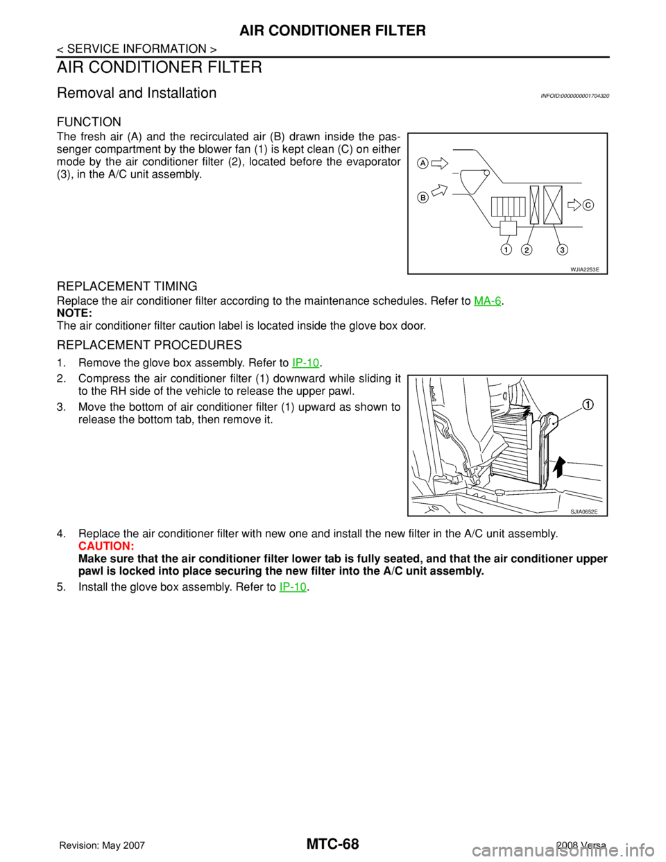
The fresh air (A) and the recirculated air (B) drawn inside the pas-
senger compartment by the blower fan (1) is kept clean (C) on either
mode by the air conditioner filter (2), located before the evaporator
(3), in the A/C unit assembly.
REPLACEMENT TIMING
Replace the air conditioner filter according to the maintenance schedules. Refer to MA-6.
NOTE:
The air conditioner filter caution label is located inside the glove box door.
REPLACEMENT PROCEDURES
1. Remove the glove box assembly. Refer to IP-10.
2. Compress the air conditioner filter (1) downward while sliding it
to the RH side of the vehicle to release the upper pawl.
3. Move the bottom of air conditioner filter (1) upward as shown to
release the bottom tab, then remove it.
4. Replace the air conditioner filter with new one and install the new filter in the A/C unit assembly.
CAUTION:
Make sure that the air conditioner filter lower tab is fully seated, and that the air conditioner upper
pawl is locked into place securing the new filter into the A/C unit assembly.
5. Install the glove box assembly. Refer to IP-10
.
WJIA2253E
SJIA0652E