2008 NISSAN LATIO washer fluid
[x] Cancel search: washer fluidPage 1017 of 2771
CVT-178
< SERVICE INFORMATION >
TRANSAXLE ASSEMBLY
TRANSAXLE ASSEMBLY
Removal and InstallationINFOID:0000000001703687
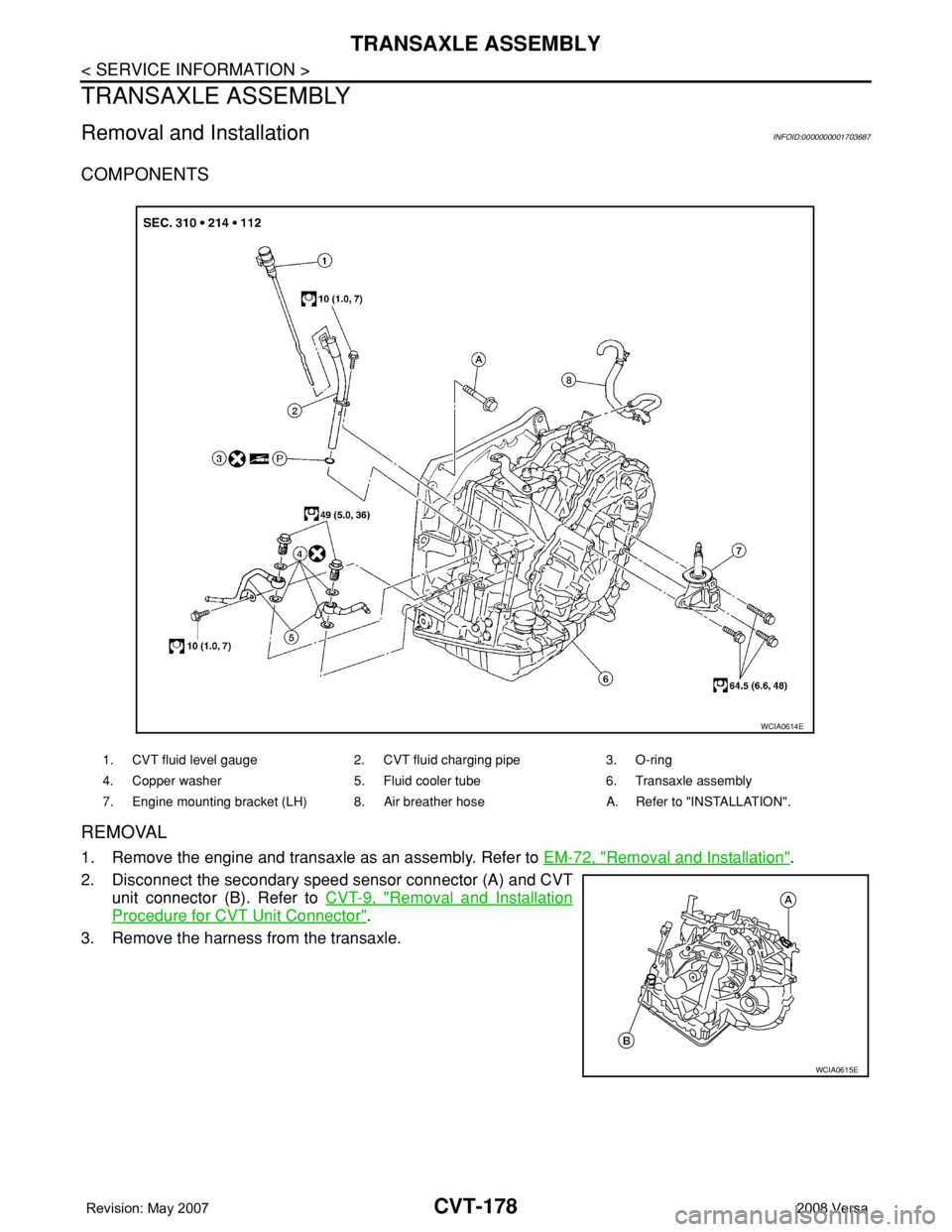
COMPONENTS
REMOVAL
1. Remove the engine and transaxle as an assembly. Refer to EM-72, "Removal and Installation".
2. Disconnect the secondary speed sensor connector (A) and CVT
unit connector (B). Refer to CVT-9, "
Removal and Installation
Procedure for CVT Unit Connector".
3. Remove the harness from the transaxle.
1. CVT fluid level gauge 2. CVT fluid charging pipe 3. O-ring
4. Copper washer 5. Fluid cooler tube 6. Transaxle assembly
7. Engine mounting bracket (LH) 8. Air breather hose A. Refer to "INSTALLATION".
WCIA0614E
WCIA0615E
Page 1018 of 2771
TRANSAXLE ASSEMBLY
CVT-179
< SERVICE INFORMATION >
D
E
F
G
H
I
J
K
L
MA
B
CVT
N
O
P
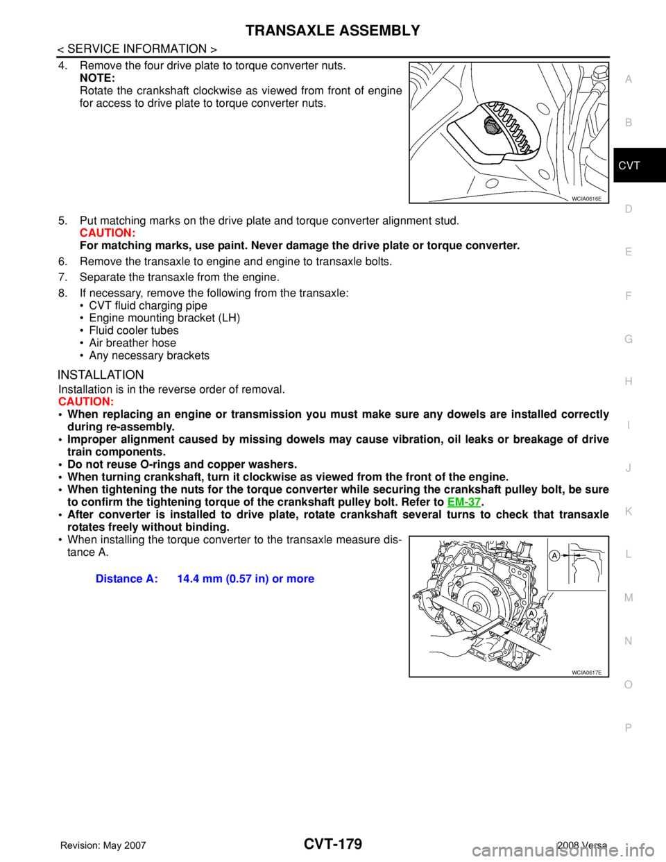
4. Remove the four drive plate to torque converter nuts.
NOTE:
Rotate the crankshaft clockwise as viewed from front of engine
for access to drive plate to torque converter nuts.
5. Put matching marks on the drive plate and torque converter alignment stud.
CAUTION:
For matching marks, use paint. Never damage the drive plate or torque converter.
6. Remove the transaxle to engine and engine to transaxle bolts.
7. Separate the transaxle from the engine.
8. If necessary, remove the following from the transaxle:
• CVT fluid charging pipe
• Engine mounting bracket (LH)
• Fluid cooler tubes
• Air breather hose
• Any necessary brackets
INSTALLATION
Installation is in the reverse order of removal.
CAUTION:
• When replacing an engine or transmission you must make sure any dowels are installed correctly
during re-assembly.
• Improper alignment caused by missing dowels may cause vibration, oil leaks or breakage of drive
train components.
• Do not reuse O-rings and copper washers.
• When turning crankshaft, turn it clockwise as viewed from the front of the engine.
• When tightening the nuts for the torque converter while securing the crankshaft pulley bolt, be sure
to confirm the tightening torque of the crankshaft pulley bolt. Refer to EM-37
.
• After converter is installed to drive plate, rotate crankshaft several turns to check that transaxle
rotates freely without binding.
• When installing the torque converter to the transaxle measure dis-
tance A.
WCIA0616E
Distance A: 14.4 mm (0.57 in) or more
WCIA0617E
Page 1032 of 2771
COMBINATION METERS
DI-11
< SERVICE INFORMATION >
C
D
E
F
G
H
I
J
L
MA
B
DI
N
O
P
Self-Diagnosis Mode of Combination MeterINFOID:0000000001704497
SELF-DIAGNOSIS MODE FUNCTION
• Self-diagnosis can check for continuity between meter control circuit and each meter (speedometer, tachom-
eter and fuel gauge).
• Self-diagnosis can check for odo/trip meter and A/T indicator (with A/T) or CVT indicator (with CVT) seg-
ment, low-fuel level warning lamp, low water temperature indicator lamp, and high water temperature warn-
ing lamp.
OPERATION PROCEDURE
1. Turn the ignition switch ON, and switch the odo/trip meter to “trip A” or “trip B”.
NOTE:
13 B Illumination control switch (-) — — Refer to LT- 1 0 5 , "System Description" .
17 GWasher fluid level switch
(Canada models)ONWasher fluid level low 0
Washer fluid level normal Battery voltage
21
BGround — — 0 22
23
24 V Fuel level sensor ground (-) ON — 0
26 BVehicle speed sensor ground
(without ABS or CVT)ON — 0
27 G Battery power supply OFF — Battery voltage
28 SB Ignition switch ON or START ON — Battery voltage
29 GR Seat belt buckle switch RH ONUnfastened (ON) 0
Fastened (OFF) Battery voltage
30 G Stop lamp switch ONBrake pedal depressed Battery voltage
Brake pedal released 0
31 V A/T N-range input (with A/T) ONTransmission gear selector lever
in N positionBattery voltage
Transmission gear selector lever
other than N position0
32 W A/T P-range input (with A/T) ONTransmission gear selector lever
in P positionBattery voltage
Transmission gear selector lever
other than P position0
33 Y A/T PN output (with A/T) ONTransmission gear selector lever
in P or N position0
Transmission gear selector lever
other than P or N positionBattery voltage
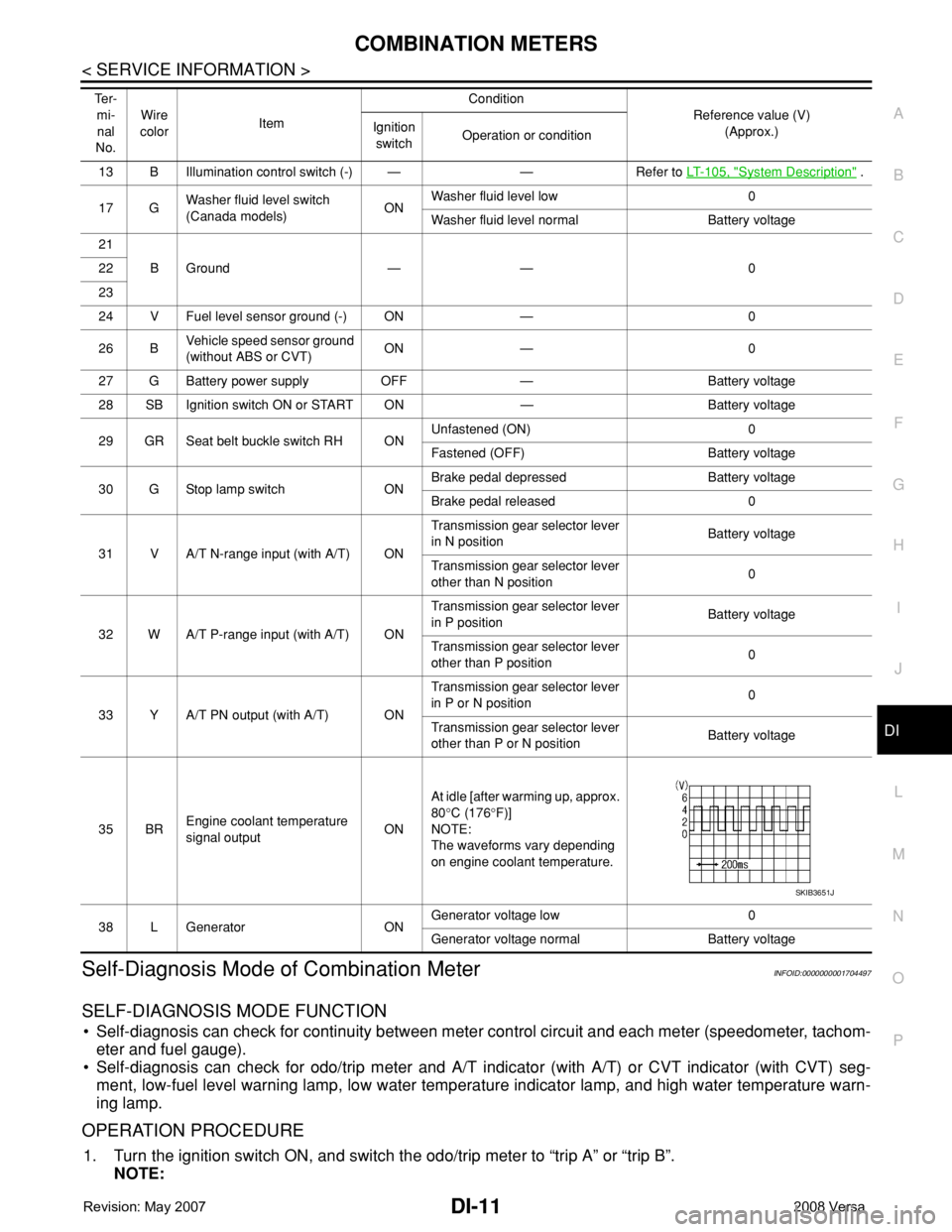
35 BREngine coolant temperature
signal outputONAt idle [after warming up, approx.
80°C (176°F)]
NOTE:
The waveforms vary depending
on engine coolant temperature.
38 L Generator ONGenerator voltage low 0
Generator voltage normal Battery voltage Te r -
mi-
nal
No.Wire
colorItemCondition
Reference value (V)
(Approx.) Ignition
switchOperation or condition
SKIB3651J
Page 1752 of 2771
ENGINE ASSEMBLY
EM-75
< SERVICE INFORMATION >
C
D
E
F
G
H
I
J
K
L
MA
EM
N
P O
• When installation directions are specified, install parts according to the directions. Refer to EM-72, "Compo-
nent".
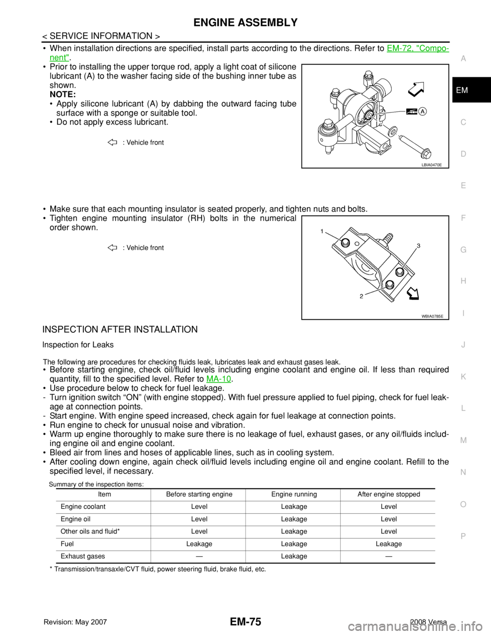
• Prior to installing the upper torque rod, apply a light coat of silicone
lubricant (A) to the washer facing side of the bushing inner tube as
shown.
NOTE:
• Apply silicone lubricant (A) by dabbing the outward facing tube
surface with a sponge or suitable tool.
• Do not apply excess lubricant.
• Make sure that each mounting insulator is seated properly, and tighten nuts and bolts.
• Tighten engine mounting insulator (RH) bolts in the numerical
order shown.
INSPECTION AFTER INSTALLATION
Inspection for Leaks
The following are procedures for checking fluids leak, lubricates leak and exhaust gases leak.
• Before starting engine, check oil/fluid levels including engine coolant and engine oil. If less than required
quantity, fill to the specified level. Refer to MA-10
.
• Use procedure below to check for fuel leakage.
- Turn ignition switch “ON” (with engine stopped). With fuel pressure applied to fuel piping, check for fuel leak-
age at connection points.
- Start engine. With engine speed increased, check again for fuel leakage at connection points.
• Run engine to check for unusual noise and vibration.
• Warm up engine thoroughly to make sure there is no leakage of fuel, exhaust gases, or any oil/fluids includ-
ing engine oil and engine coolant.
• Bleed air from lines and hoses of applicable lines, such as in cooling system.
• After cooling down engine, again check oil/fluid levels including engine oil and engine coolant. Refill to the
specified level, if necessary.
Summary of the inspection items:
* Transmission/transaxle/CVT fluid, power steering fluid, brake fluid, etc.: Vehicle front
LBIA0470E
: Vehicle front
WBIA0785E
Item Before starting engine Engine running After engine stopped
Engine coolant Level Leakage Level
Engine oil Level Leakage Level
Other oils and fluid* Level Leakage Level
Fuel Leakage Leakage Leakage
Exhaust gases — Leakage —
Page 1854 of 2771
PRECAUTIONS
GI-3
< SERVICE INFORMATION >
C
D
E
F
G
H
I
J
K
L
MB
GI
N
O
P
General PrecautionINFOID:0000000001702424
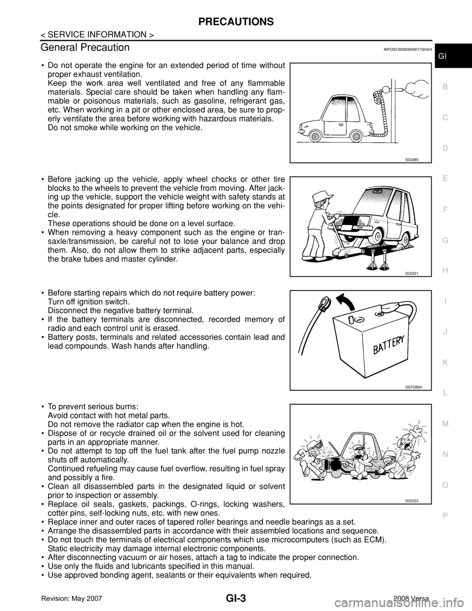
• Do not operate the engine for an extended period of time without
proper exhaust ventilation.
Keep the work area well ventilated and free of any flammable
materials. Special care should be taken when handling any flam-
mable or poisonous materials, such as gasoline, refrigerant gas,
etc. When working in a pit or other enclosed area, be sure to prop-
erly ventilate the area before working with hazardous materials.
Do not smoke while working on the vehicle.
• Before jacking up the vehicle, apply wheel chocks or other tire
blocks to the wheels to prevent the vehicle from moving. After jack-
ing up the vehicle, support the vehicle weight with safety stands at
the points designated for proper lifting before working on the vehi-
cle.
These operations should be done on a level surface.
• When removing a heavy component such as the engine or tran-
saxle/transmission, be careful not to lose your balance and drop
them. Also, do not allow them to strike adjacent parts, especially
the brake tubes and master cylinder.
• Before starting repairs which do not require battery power:
Turn off ignition switch.
Disconnect the negative battery terminal.
• If the battery terminals are disconnected, recorded memory of
radio and each control unit is erased.
• Battery posts, terminals and related accessories contain lead and
lead compounds. Wash hands after handling.
• To prevent serious burns:
Avoid contact with hot metal parts.
Do not remove the radiator cap when the engine is hot.
• Dispose of or recycle drained oil or the solvent used for cleaning
parts in an appropriate manner.
• Do not attempt to top off the fuel tank after the fuel pump nozzle
shuts off automatically.
Continued refueling may cause fuel overflow, resulting in fuel spray
and possibly a fire.
• Clean all disassembled parts in the designated liquid or solvent
prior to inspection or assembly.
• Replace oil seals, gaskets, packings, O-rings, locking washers,
cotter pins, self-locking nuts, etc. with new ones.
• Replace inner and outer races of tapered roller bearings and needle bearings as a set.
• Arrange the disassembled parts in accordance with their assembled locations and sequence.
• Do not touch the terminals of electrical components which use microcomputers (such as ECM).
Static electricity may damage internal electronic components.
• After disconnecting vacuum or air hoses, attach a tag to indicate the proper connection.
• Use only the fluids and lubricants specified in this manual.
• Use approved bonding agent, sealants or their equivalents when required.
SGI285
SGI231
SEF289H
SGI233
Page 1860 of 2771
HOW TO USE THIS MANUAL
GI-9
< SERVICE INFORMATION >
C
D
E
F
G
H
I
J
K
L
MB
GI
N
O
P
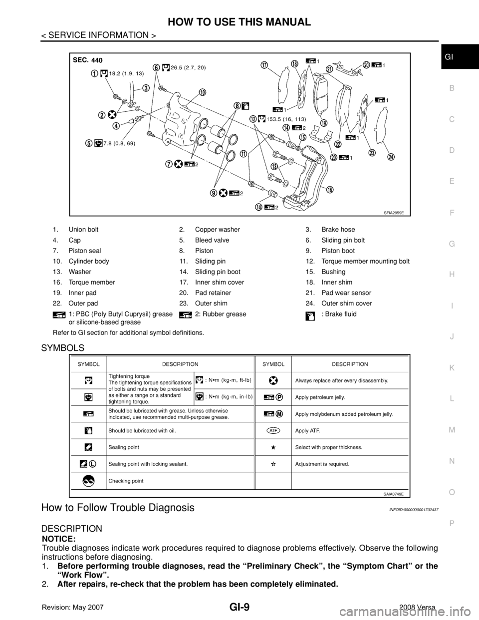
SYMBOLS
How to Follow Trouble DiagnosisINFOID:0000000001702437
DESCRIPTION
NOTICE:
Trouble diagnoses indicate work procedures required to diagnose problems effectively. Observe the following
instructions before diagnosing.
1.Before performing trouble diagnoses, read the “Preliminary Check”, the “Symptom Chart” or the
“Work Flow”.
2.After repairs, re-check that the problem has been completely eliminated.
1. Union bolt 2. Copper washer 3. Brake hose
4. Cap 5. Bleed valve 6. Sliding pin bolt
7. Piston seal 8. Piston 9. Piston boot
10. Cylinder body 11. Sliding pin 12. Torque member mounting bolt
13. Washer 14. Sliding pin boot 15. Bushing
16. Torque member 17. Inner shim cover 18. Inner shim
19. Inner pad 20. Pad retainer 21. Pad wear sensor
22. Outer pad 23. Outer shim 24. Outer shim cover
1: PBC (Poly Butyl Cuprysil) grease
or silicone-based grease2: Rubber grease : Brake fluid
Refer to GI section for additional symbol definitions.
SFIA2959E
SAIA0749E
Page 2270 of 2771
MA-10
< SERVICE INFORMATION >
RECOMMENDED FLUIDS AND LUBRICANTS
RECOMMENDED FLUIDS AND LUBRICANTS
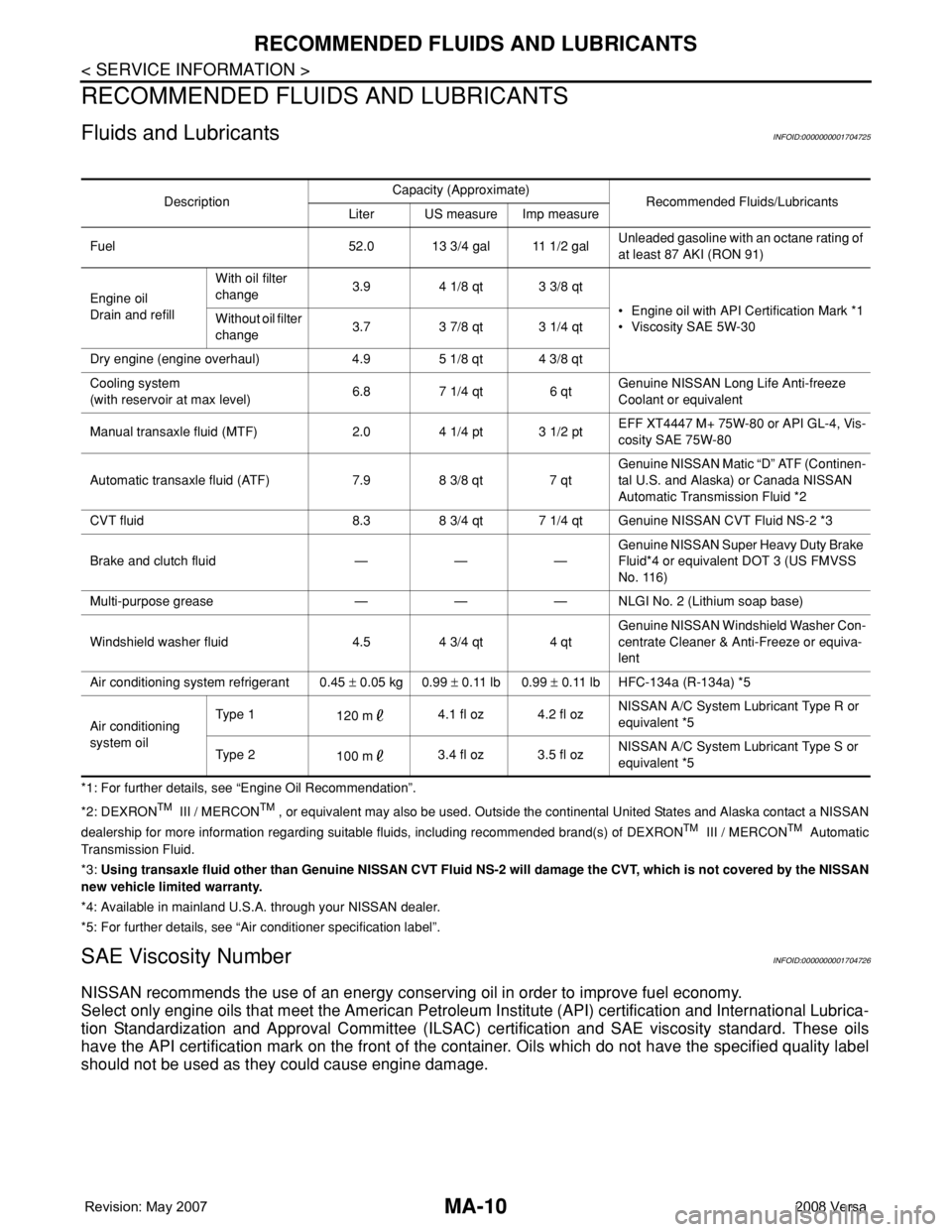
Fluids and LubricantsINFOID:0000000001704725
*1: For further details, see “Engine Oil Recommendation”.
*2: DEXRON
TM III / MERCONTM , or equivalent may also be used. Outside the continental United States and Alaska contact a NISSAN
dealership for more information regarding suitable fluids, including recommended brand(s) of DEXRONTM III / MERCONTM Automatic
Transmission Fluid.
*3: Using transaxle fluid other than Genuine NISSAN CVT Fluid NS-2 will damage the CVT, which is not covered by the NISSAN
new vehicle limited warranty.
*4: Available in mainland U.S.A. through your NISSAN dealer.
*5: For further details, see “Air conditioner specification label”.
SAE Viscosity NumberINFOID:0000000001704726
NISSAN recommends the use of an energy conserving oil in order to improve fuel economy.
Select only engine oils that meet the American Petroleum Institute (API) certification and International Lubrica-
tion Standardization and Approval Committee (ILSAC) certification and SAE viscosity standard. These oils
have the API certification mark on the front of the container. Oils which do not have the specified quality label
should not be used as they could cause engine damage.
DescriptionCapacity (Approximate)
Recommended Fluids/Lubricants
Liter US measure Imp measure
Fuel 52.0 13 3/4 gal 11 1/2 galUnleaded gasoline with an octane rating of
at least 87 AKI (RON 91)
Engine oil
Drain and refillWith oil filter
change3.9 4 1/8 qt 3 3/8 qt
• Engine oil with API Certification Mark *1
• Viscosity SAE 5W-30 Without oil filter
change3.7 3 7/8 qt 3 1/4 qt
Dry engine (engine overhaul) 4.9 5 1/8 qt 4 3/8 qt
Cooling system
(with reservoir at max level)6.8 7 1/4 qt 6 qtGenuine NISSAN Long Life Anti-freeze
Coolant or equivalent
Manual transaxle fluid (MTF) 2.0 4 1/4 pt 3 1/2 ptEFF XT4447 M+ 75W-80 or API GL-4, Vis-
cosity SAE 75W-80
Automatic transaxle fluid (ATF) 7.9 8 3/8 qt 7 qtGenuine NISSAN Matic “D” ATF (Continen-
tal U.S. and Alaska) or Canada NISSAN
Automatic Transmission Fluid *2
CVT fluid 8.3 8 3/4 qt 7 1/4 qt Genuine NISSAN CVT Fluid NS-2 *3
Brake and clutch fluid — — —Genuine NISSAN Super Heavy Duty Brake
Fluid*4 or equivalent DOT 3 (US FMVSS
No. 116)
Multi-purpose grease — — — NLGI No. 2 (Lithium soap base)
Windshield washer fluid 4.5 4 3/4 qt 4 qtGenuine NISSAN Windshield Washer Con-
centrate Cleaner & Anti-Freeze or equiva-
lent
Air conditioning system refrigerant 0.45 ± 0.05 kg 0.99 ± 0.11 lb 0.99 ± 0.11 lb HFC-134a (R-134a) *5
Air conditioning
system oilTyp e 1
120 m4.1 fl oz 4.2 fl ozNISSAN A/C System Lubricant Type R or
equivalent *5
Typ e 2
100 m3.4 fl oz 3.5 fl ozNISSAN A/C System Lubricant Type S or
equivalent *5
Page 2304 of 2771
MT-16
< SERVICE INFORMATION >
TRANSAXLE ASSEMBLY
TRANSAXLE ASSEMBLY
Removal and InstallationINFOID:0000000001703141
CAUTION:
If transaxle assembly is removed from the vehicle, always replace CSC (Concentric Slave Cylinder).
Inserted CSC returns to the original position when removing transaxle assembly. Dust on clutch disc
sliding parts may damage CSC seal, and may cause clutch fluid leakage.
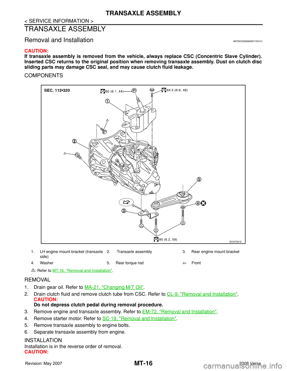
COMPONENTS
REMOVAL
1. Drain gear oil. Refer to MA-21, "Changing M/T Oil".
2. Drain clutch fluid and remove clutch tube from CSC. Refer to CL-9, "
Removal and Installation".
CAUTION:
Do not depress clutch pedal during removal procedure.
3. Remove engine and transaxle assembly. Refer to EM-72, "
Removal and Installation".
4. Remove starter motor. Refer to SC-19, "
Removal and Installation".
5. Remove transaxle assembly to engine bolts.
6. Separate transaxle assembly from engine.
INSTALLATION
Installation is in the reverse order of removal.
CAUTION:
1. LH engine mount bracket (transaxle
side)2. Transaxle assembly 3. Rear engine mount bracket
4. Washer 5. Rear torque rod⇐Front
: Refer to MT-16, "
Removal and Installation".
SCIA7631E