Page 2160 of 2771
HEADLAMP (FOR USA)
LT-23
< SERVICE INFORMATION >
C
D
E
F
G
H
I
J
L
MA
B
LT
N
O
P
2. Remove the headlamp. Refer to LT-23, "Removal and Installation".
3. Turn bulb socket counterclockwise and unlock it.
4. Remove bulb from its socket.
FRONT TURN SIGNAL LAMP
1. Turn lighting switch OFF.
2. Remove the headlamp. Refer to LT-23, "
Removal and Installation".
3. Turn bulb socket counterclockwise and unlock it.
4. Remove bulb from its socket.
Removal and InstallationINFOID:0000000001704379
REMOVAL
1. Disconnect the negative battery terminal.
2. Remove front bumper fascia. Refer to EI-14
.
3. Remove headlamp bolts (A).
4. Pull headlamp (1) toward the vehicle front, disconnect connec-
tor, and remove headlamp.
INSTALLATION
Installation is in the reverse order of removal.
• After installation, perform aiming adjustment. Refer to LT-21, "
Aiming Adjustment".
Disassembly and AssemblyINFOID:0000000001704380
PKIC1223E
WKIA5418E
Page 2161 of 2771
LT-24
< SERVICE INFORMATION >
HEADLAMP (FOR USA)
DISASSEMBLY
1. Remove back cover.
2. Unlock retaining spring and remove bulb (High/Low).
3. Turn parking (clearance) lamp bulb socket counterclockwise and unlock it.
4. Remove parking (clearance) lamp bulb from its socket.
5. Turn front turn signal lamp bulb socket counterclockwise and unlock it.
6. Remove front turn signal lamp bulb from its socket.
7. Remove the bumper stay.
ASSEMBLY
Assembly is in the reverse order of disassembly.
CAUTION:
• After installing bulb, be sure to install plastic cap securely to insure water tight seal.
1. Retaining spring 2. Parking (clearance) lamp bulb 3. Parking (clearance) lamp bulb socket
4. Halogen bulb (High/Low) 5. Back cover 6. Front turn signal lamp bulb socket
7. Front turn signal lamp bulb 8. Headlamp housing assembly 9. Bumper stay
A. Screw
Page 2174 of 2771
HEADLAMP (FOR CANADA) - DAYTIME LIGHT SYSTEM -
LT-37
< SERVICE INFORMATION >
C
D
E
F
G
H
I
J
L
MA
B
LT
N
O
P
2. Remove the headlamp. Refer to LT-23, "Removal and Installation".
3. Turn bulb socket counterclockwise and unlock it.
4. Remove bulb from its socket.
FRONT TURN SIGNAL LAMP
1. Turn lighting switch OFF.
2. Remove the headlamp. Refer to LT-23, "
Removal and Installation".
3. Turn bulb socket counterclockwise and unlock it.
4. Remove bulb from its socket.
Removal and InstallationINFOID:0000000001704395
REMOVAL
1. Disconnect the negative battery terminal.
2. Remove front bumper fascia. Refer to EI-14
.
3. Remove headlamp bolts (A).
4. Pull headlamp (1) toward the vehicle front, disconnect connec-
tor, and remove headlamp.
INSTALLATION
Installation is in the reverse order of removal.
• After installation, perform aiming adjustment. Refer to LT-35, "
Aiming Adjustment".
Disassembly and AssemblyINFOID:0000000001704396
PKIC1223E
WKIA5418E
Page 2175 of 2771
LT-38
< SERVICE INFORMATION >
HEADLAMP (FOR CANADA) - DAYTIME LIGHT SYSTEM -
DISASSEMBLY
1. Remove back cover.
2. Unlock retaining spring and remove bulb (High/Low).
3. Turn parking (clearance) lamp bulb socket counterclockwise and unlock it.
4. Remove parking (clearance) lamp bulb from its socket.
5. Turn front turn signal lamp bulb socket counterclockwise and unlock it.
6. Remove front turn signal lamp bulb from its socket.
7. Remove the bumper stay.
ASSEMBLY
Assembly is in the reverse order of disassembly.
CAUTION:
• After installing bulb, be sure to install plastic cap securely to insure water tight seal.
1. Retaining spring 2. Parking (clearance) lamp bulb 3. Parking (clearance) lamp bulb socket
4. Halogen bulb (High/Low) 5. Back cover 6. Front turn signal lamp bulb socket
7. Front turn signal lamp bulb 8. Headlamp housing assembly 9. Bumper stay
A. Screw
Page 2193 of 2771

LT-56
< SERVICE INFORMATION >
TURN SIGNAL AND HAZARD WARNING LAMPS
3. Perform the preliminary check. Refer to LT-56, "Preliminary Check" .
4. Check symptom and repair or replace the cause of the malfunction.
5. Do turn signal and hazard warning lamps operate normally? If YES, GO TO 6. If NO, GO TO 4.
6. INSPECTION END
Preliminary CheckINFOID:0000000001704419
CHECK POWER SUPPLY AND GROUND CIRCUIT FOR BCM
Refer to BCS-15, "BCM Power Supply and Ground Circuit Inspection" .
CONSULT-III Function (BCM)INFOID:0000000001704420
Refer to LT- 11 , "CONSULT-III Function (BCM)" .
Turn Signals Do Not OperateINFOID:0000000001704421
1.CHECK COMBINATION SWITCH INPUT SIGNAL
With CONSULT-III
1. Select “BCM” on CONSULT-III. Select “FLASHER” on “SELECT TEST ITEM” screen.
2. Select “DATA MONITOR” on “SELECT DIAG MODE” screen. Make sure that “TURN SIGNAL R” and
“TURN SIGNAL L” turns ON-OFF linked with operation of lighting switch.
Without CONSULT-III
Refer to LT-63, "
Combination Switch Inspection" .
OK or NG
OK >> Replace the BCM. BCS-18, "Removal and Installation of BCM"
NG >> Check combination switch (lighting switch). Refer to LT-63, "Combination Switch Inspection" .
Front Turn Signal Lamp Does Not OperateINFOID:0000000001704422
1.CHECK BULB
Verify the bulb standard of each turn signal lamp is correct. Refer to LT-113, "
Exterior Lamp" .
OK or NG
OK >> GO TO 2.
NG >> Replace turn signal lamp bulb. Refer to LT-59, "
Bulb Replacement for Front Turn Signal Lamp" .
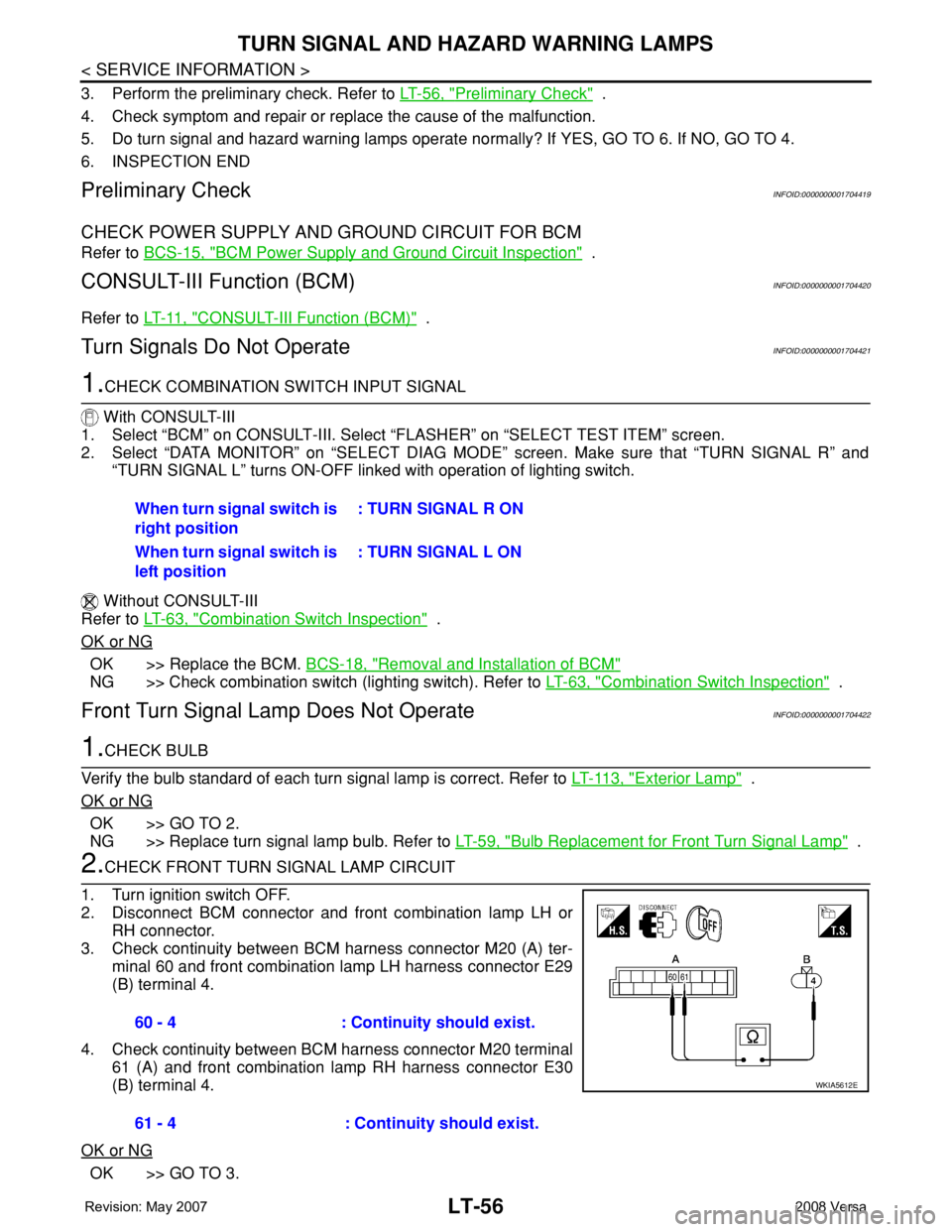
2.CHECK FRONT TURN SIGNAL LAMP CIRCUIT
1. Turn ignition switch OFF.
2. Disconnect BCM connector and front combination lamp LH or
RH connector.
3. Check continuity between BCM harness connector M20 (A) ter-
minal 60 and front combination lamp LH harness connector E29
(B) terminal 4.
4. Check continuity between BCM harness connector M20 terminal
61 (A) and front combination lamp RH harness connector E30
(B) terminal 4.
OK or NG
OK >> GO TO 3.When turn signal switch is
right position: TURN SIGNAL R ON
When turn signal switch is
left position: TURN SIGNAL L ON
60 - 4 : Continuity should exist.
61 - 4 : Continuity should exist.
WKIA5612E
Page 2194 of 2771

TURN SIGNAL AND HAZARD WARNING LAMPS
LT-57
< SERVICE INFORMATION >
C
D
E
F
G
H
I
J
L
MA
B
LT
N
O
P
NG >> Repair harness or connector.
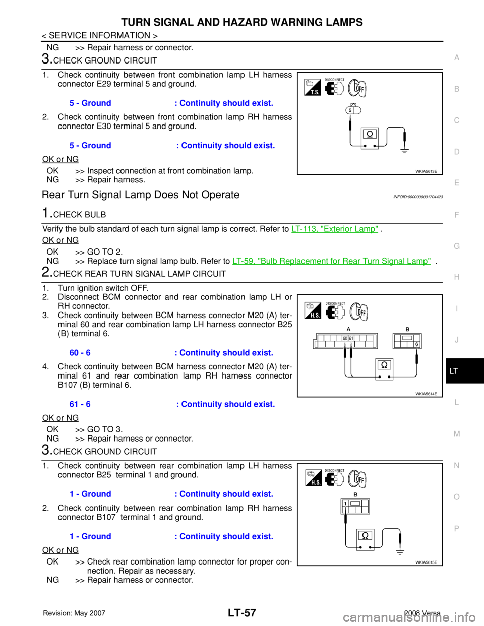
3.CHECK GROUND CIRCUIT
1. Check continuity between front combination lamp LH harness
connector E29 terminal 5 and ground.
2. Check continuity between front combination lamp RH harness
connector E30 terminal 5 and ground.
OK or NG
OK >> Inspect connection at front combination lamp.
NG >> Repair harness.
Rear Turn Signal Lamp Does Not OperateINFOID:0000000001704423
1.CHECK BULB
Verify the bulb standard of each turn signal lamp is correct. Refer to LT-113, "
Exterior Lamp" .
OK or NG
OK >> GO TO 2.
NG >> Replace turn signal lamp bulb. Refer to LT-59, "
Bulb Replacement for Rear Turn Signal Lamp" .
2.CHECK REAR TURN SIGNAL LAMP CIRCUIT
1. Turn ignition switch OFF.
2. Disconnect BCM connector and rear combination lamp LH or
RH connector.
3. Check continuity between BCM harness connector M20 (A) ter-
minal 60 and rear combination lamp LH harness connector B25
(B) terminal 6.
4. Check continuity between BCM harness connector M20 (A) ter-
minal 61 and rear combination lamp RH harness connector
B107 (B) terminal 6.
OK or NG
OK >> GO TO 3.
NG >> Repair harness or connector.
3.CHECK GROUND CIRCUIT
1. Check continuity between rear combination lamp LH harness
connector B25 terminal 1 and ground.
2. Check continuity between rear combination lamp RH harness
connector B107 terminal 1 and ground.
OK or NG
OK >> Check rear combination lamp connector for proper con-
nection. Repair as necessary.
NG >> Repair harness or connector.5 - Ground : Continuity should exist.
5 - Ground : Continuity should exist.
WKIA5613E
60 - 6 : Continuity should exist.
61 - 6 : Continuity should exist.
WKIA5614E
1 - Ground : Continuity should exist.
1 - Ground : Continuity should exist.
WKIA5615E
Page 2196 of 2771

TURN SIGNAL AND HAZARD WARNING LAMPS
LT-59
< SERVICE INFORMATION >
C
D
E
F
G
H
I
J
L
MA
B
LT
N
O
P
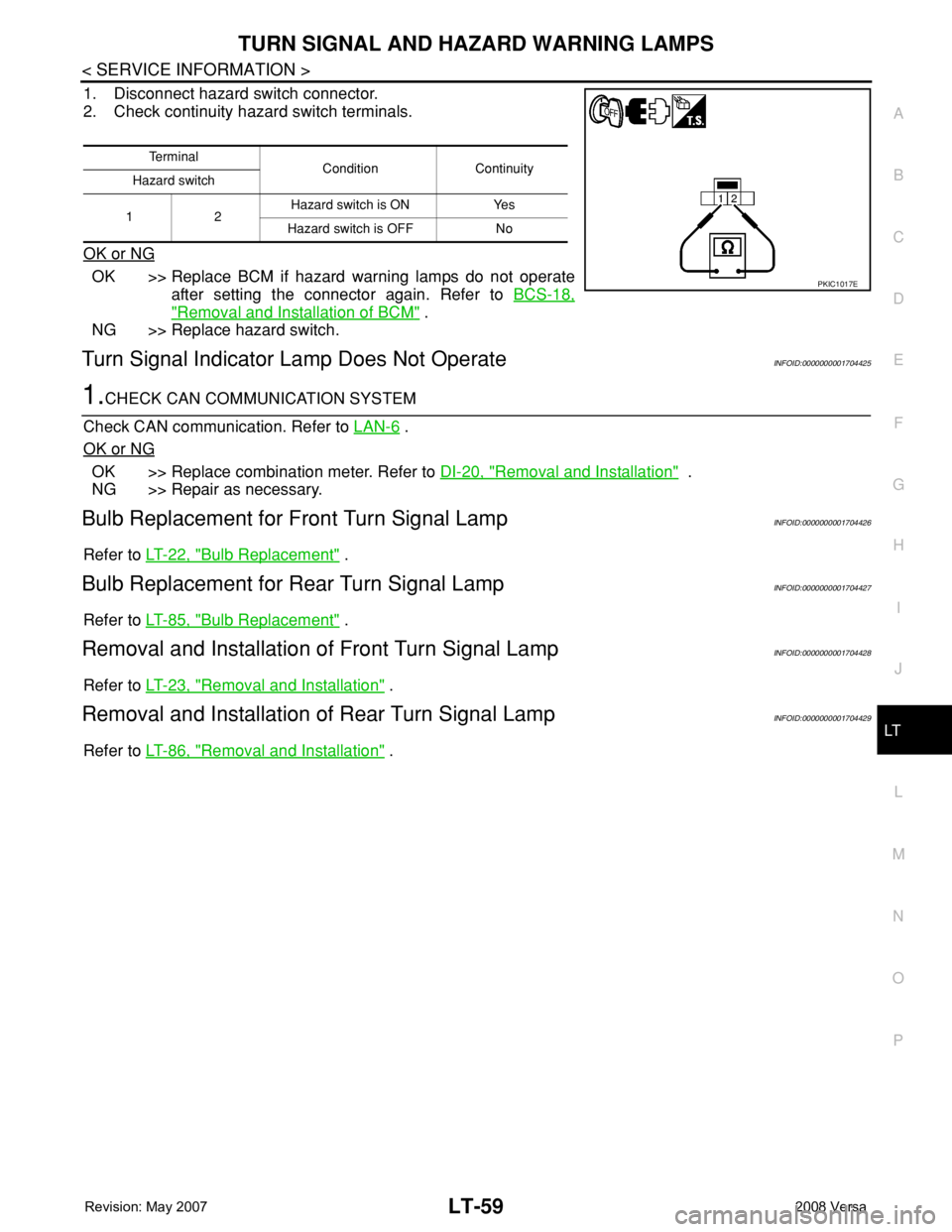
1. Disconnect hazard switch connector.
2. Check continuity hazard switch terminals.
OK or NG
OK >> Replace BCM if hazard warning lamps do not operate
after setting the connector again. Refer to BCS-18,
"Removal and Installation of BCM" .
NG >> Replace hazard switch.
Turn Signal Indicator Lamp Does Not OperateINFOID:0000000001704425
1.CHECK CAN COMMUNICATION SYSTEM
Check CAN communication. Refer to LAN-6
.
OK or NG
OK >> Replace combination meter. Refer to DI-20, "Removal and Installation" .
NG >> Repair as necessary.
Bulb Replacement for Front Turn Signal LampINFOID:0000000001704426
Refer to LT-22, "Bulb Replacement" .
Bulb Replacement for Rear Turn Signal LampINFOID:0000000001704427
Refer to LT-85, "Bulb Replacement" .
Removal and Installation of Front Turn Signal LampINFOID:0000000001704428
Refer to LT-23, "Removal and Installation" .
Removal and Installation of Rear Turn Signal LampINFOID:0000000001704429
Refer to LT-86, "Removal and Installation" .
Te r m i n a l
Condition Continuity
Hazard switch
12Hazard switch is ON Yes
Hazard switch is OFF No
PKIC1017E
Page 2222 of 2771
REAR COMBINATION LAMP
LT-85
< SERVICE INFORMATION >
C
D
E
F
G
H
I
J
L
MA
B
LT
N
O
P
REAR COMBINATION LAMP
ComponentINFOID:0000000001704462
Hatchback
Bulb ReplacementINFOID:0000000001704463
HATCHBACK
1. Remove the rear combination lamp. Refer to LT-86, "Removal and Installation".
2. Turn bulb socket counterclockwise and unlock it.
3. Remove bulb.
4. Installation is in the reverse order of removal.
SEDAN
1. Remove trunk side finisher. Refer to EI-53, "Removal and Installation".
2. Turn bulb socket counterclockwise and unlock it.
3. Remove the stop/tail lamp bulb (1), turn signal lamp bulb (2),
and the back-up lamp bulb (3).
4. Installation is in the reverse order of removal.
LKIA0760E
1. Rear combination lamp harness 2. Turn signal lamp bulb 3. Back-up lamp bulb
4. Stop/tail lamp bulb 5. Rear combination lamp housing as-
sembly6. Bumper stay
A. Grommet B. Nut C. Clip
D. Nuts E. Clip
PKIC1034E