Page 91 of 2771

TROUBLE DIAGNOSIS
AT-79
< SERVICE INFORMATION >
D
E
F
G
H
I
J
K
L
MA
B
AT
N
O
P
4. Turn ignition switch ON. (Do not start engine.)
Does OD OFF indicator lamp come on about 2 seconds?
YES >> GO TO 2.
NO >> Stop procedure. Perform AT-176, "
OD OFF Indicator
Lamp Does Not Come On" before proceeding.
2.JUDGEMENT PROCEDURE STEP 1
1. Turn ignition switch OFF.
2. Keep pressing shift lock release button.
3. Move selector lever from “P” to “D” position.
4. Turn ignition switch ON. (Do not start engine.)
5. Keep pressing overdrive control switch while OD OFF indicator lamp is lighting up for 2 seconds. (OD
OFF indicator lamp is on.)
6. Keep pressing overdrive control switch and shift selector lever to the “2” position. (OD OFF indicator lamp
is on.)
7. Stop pressing overdrive control switch. (OD OFF indicator lamp is on.)
8. Shift selector lever to the “1” position. (OD OFF indicator lamp is on.)
9. Keep pressing overdrive control switch. (OD OFF indicator lamp is off.)
10. Depress accelerator pedal fully while pressing overdrive control switch.
>> GO TO 3.
3.CHECK SELF-DIAGNOSIS CODE
Check OD OFF indicator lamp. Refer to "Judgement of Self-diagnosis Code" .
>>DIAGNOSIS END
Judgement of Self-diagnosis Code
SCIA7140E
Page 204 of 2771

AT-192
< SERVICE INFORMATION >
TROUBLE DIAGNOSIS FOR SYMPTOMS
OK >>INSPECTION END
NG >> GO TO 3.
3.CHECK TCM
1. Check TCM input/output signals. Refer to AT-71, "
TCM Terminal and Reference Value" .
2. If NG, recheck TCM pin terminals for damage or loose connection with harness connector.
OK or NG
OK >>INSPECTION END
NG >> Repair or replace damaged parts.
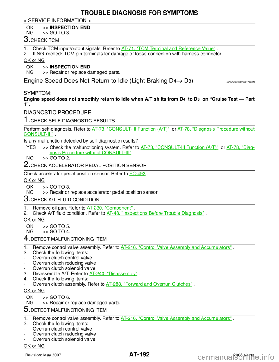
Engine Speed Does Not Return to Idle (Light Braking D4→ D3)INFOID:0000000001703349
SYMPTOM:
Engine speed does not smoothly return to idle when A/T shifts from D4 to D3 on “Cruise Test — Part
1”.
DIAGNOSTIC PROCEDURE
1.CHECK SELF-DIAGNOSTIC RESULTS
Perform self-diagnosis. Refer to AT-73, "
CONSULT-III Function (A/T)" or AT-78, "Diagnosis Procedure without
CONSULT-III" .
Is any malfunction detected by self-diagnostic results?
YES >> Check the malfunctioning system. Refer to AT-73, "CONSULT-III Function (A/T)" or AT-78, "Diag-
nosis Procedure without CONSULT-III" .
NO >> GO TO 2.
2.CHECK ACCELERATOR PEDAL POSITION SENSOR
Check accelerator pedal position sensor. Refer to EC-493
.
OK or NG
OK >> GO TO 3.
NG >> Repair or replace accelerator pedal position sensor.
3.CHECK A/T FLUID CONDITION
1. Remove oil pan. Refer to AT-230, "
Component" .
2. Check A/T fluid condition. Refer to AT-48, "
Inspections Before Trouble Diagnosis" .
OK or NG
OK >> GO TO 5.
NG >> GO TO 4.
4.DETECT MALFUNCTIONING ITEM
1. Remove control valve assembly. Refer to AT-216, "
Control Valve Assembly and Accumulators" .
2. Check the following items:
- Overrun clutch control valve
- Overrun clutch reducing valve
- Overrun clutch solenoid valve
3. Disassemble A/T. Refer to AT-240, "
Disassembly" .
4. Check the following items:
- Overrun clutch assembly. Refer to AT-288, "
Forward and Overrun Clutches" .
OK or NG
OK >> GO TO 6.
NG >> Repair or replace damaged parts.
5.DETECT MALFUNCTIONING ITEM
1. Remove control valve assembly. Refer to AT-216, "
Control Valve Assembly and Accumulators" .
2. Check the following items:
- Overrun clutch control valve
- Overrun clutch reducing valve
- Overrun clutch solenoid valve
OK or NG
Page 217 of 2771
SHIFT CONTROL SYSTEM
AT-205
< SERVICE INFORMATION >
D
E
F
G
H
I
J
K
L
MA
B
AT
N
O
P
7. Remove the plate (1) from the control device assembly.
: Vehicle front
8. Remove the lock plate (1) from the control cable (2).
: Vehicle front
9. Remove the control cable (2) from the control device assembly.
10. Insert flat-bladed screwdrivers at points (A) and (B) as shown,
and press both tabs (E) and (F) at the front (C) and rear (D)
slightly toward the center of the control device assembly to
remove the control device assembly from the underside of the
vehicle.
: Vehicle front
INSTALLATION
Installation is in the reverse order of removal.
SCIA6967E
SCIA6968E
SCIA6970E
Page 218 of 2771

AT-206
< SERVICE INFORMATION >
SHIFT CONTROL SYSTEM
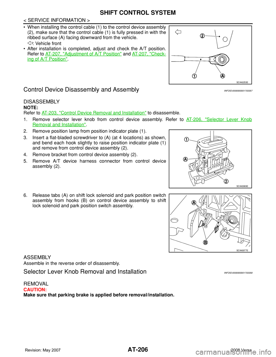
• When installing the control cable (1) to the control device assembly
(2), make sure that the control cable (1) is fully pressed in with the
ribbed surface (A) facing downward from the vehicle.
: Vehicle front
• After installation is completed, adjust and check the A/T position.
Refer to AT-207, "
Adjustment of A/T Position" and AT-207, "Check-
ing of A/T Position".
Control Device Disassembly and AssemblyINFOID:0000000001703357
DISASSEMBLY
NOTE:
Refer to AT-203, "
Control Device Removal and Installation" to disassemble.
1. Remove selector lever knob from control device assembly. Refer to AT-206, "
Selector Lever Knob
Removal and Installation".
2. Remove position lamp from position indicator plate (1).
3. Insert a flat-bladed screwdriver to (A) (at 4 locations) as shown,
and bend each hook slightly to raise position indicator plate (1)
and remove from control device assembly (2).
4. Remove bracket from control device assembly (2).
5. Remove A/T device harness connector from control device
assembly (2).
6. Release tabs (A) on shift lock solenoid and park position switch
assembly from hooks (B) on control device assembly to shift
lock solenoid and park position switch assembly.
ASSEMBLY
Assemble in the reverse order of disassembly.
Selector Lever Knob Removal and InstallationINFOID:0000000001703358
REMOVAL
CAUTION:
Make sure that parking brake is applied before removal/installation.
SCIA6253E
SCIA6969E
SCIA6977E
Page 257 of 2771
DISASSEMBLY
AT-245
< SERVICE INFORMATION >
D
E
F
G
H
I
J
K
L
MA
B
AT
N
O
P
a. Remove converter housing fitting bolts (1) and (2) using a power
tool.
b. Remove bracket from converter housing
c. Remove converter housing by tapping it lightly.
d. Remove O-ring from differential lubricant hole.
24. Remove final drive assembly from transaxle case.
25. Remove differential side bearing outer race from transaxle case
and converter housing.
26. Remove differential side bearing adjusting shim from transaxle
case.
SCIA7970E
SCIA3281E
SAT228F
SCIA5378E
SCIA4938E
Page 265 of 2771
DISASSEMBLY
AT-253
< SERVICE INFORMATION >
D
E
F
G
H
I
J
K
L
MA
B
AT
N
O
P
43. Remove forward clutch assembly and overrun clutch assembly
(1) from transaxle case.
44. Remove needle bearing (1) and thrust washer (2) from bearing
retainer.
•Inspect needle bearing (1) and thrust washer (2), and
replace damaged or worn.
45. Remove output shaft assembly according to the following procedures.
a. Remove side cover fitting bolts.
CAUTION:
• Do not mix bolts A and B.
• Always replace bolts A as they are self-sealing bolts.
b. Remove side cover by lightly tapping it using a soft hammer.
CAUTION:
• Be careful not to drop output shaft assembly. It might
come out when removing side cover.
• Be careful not to damage side cover.
SCIA5900J
SCIA5901J
SCIA7939E
SAT434D
Page 283 of 2771
REPAIR FOR COMPONENT PARTS
AT-271
< SERVICE INFORMATION >
D
E
F
G
H
I
J
K
L
MA
B
AT
N
O
P
i. Install control valve lower body (1) on control valve inter body (2)
using reamer bolts (F) as guides, and tighten reamer bolts (F)
slightly.
2. Install O-rings on solenoid valves and terminal body.
3. Install and tighten bolts.
(1): Control valve upper body
(2): Control valve inter body
(3): Control valve lower body
(4): Support plate
Bolt length, number and location:
*: Reamer bolt and nut.
SCIA7014E
SCIA7180E
SCIA7058E
Bolt symbol A B C D E F*G
Bolt length “ ” [mm (in)]
13.5
(0.531)58.0
(2.283) 40.0
(1.575)66.0
(2.598)33.0
(1.299)78.0
(3.071)18.0
(0.709)
Number of bolts 6 3 6 11 2 2 1
Tightening torque
[N·m (kg-m, in-lb)]7.84 (0.80, 69)3.92
(0.40, 35)7.84 (0.80, 69)
Page 286 of 2771

AT-274
< SERVICE INFORMATION >
REPAIR FOR COMPONENT PARTS
DISASSEMBLY
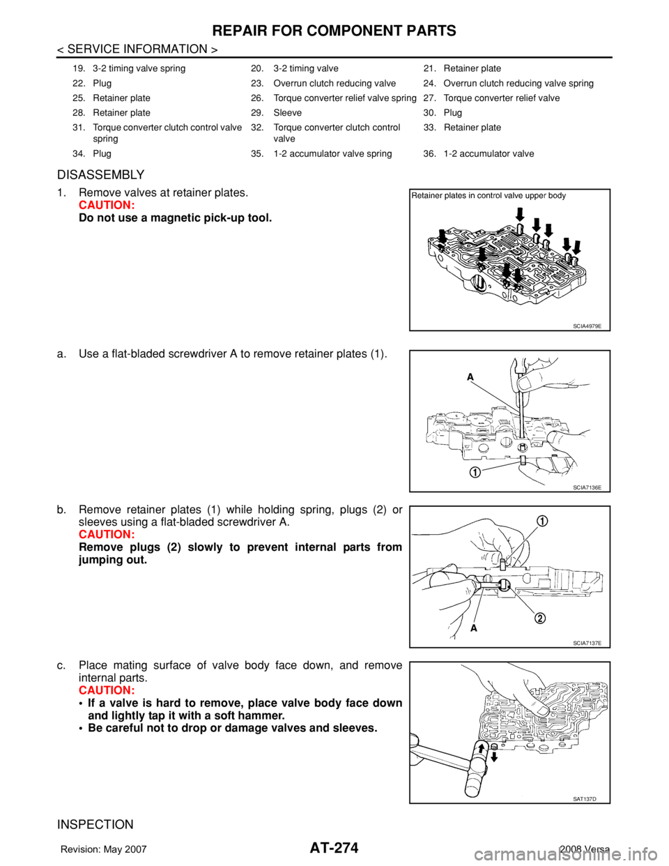
1. Remove valves at retainer plates.
CAUTION:
Do not use a magnetic pick-up tool.
a. Use a flat-bladed screwdriver A to remove retainer plates (1).
b. Remove retainer plates (1) while holding spring, plugs (2) or
sleeves using a flat-bladed screwdriver A.
CAUTION:
Remove plugs (2) slowly to prevent internal parts from
jumping out.
c. Place mating surface of valve body face down, and remove
internal parts.
CAUTION:
• If a valve is hard to remove, place valve body face down
and lightly tap it with a soft hammer.
• Be careful not to drop or damage valves and sleeves.
INSPECTION
19. 3-2 timing valve spring 20. 3-2 timing valve 21. Retainer plate
22. Plug 23. Overrun clutch reducing valve 24. Overrun clutch reducing valve spring
25. Retainer plate 26. Torque converter relief valve spring 27. Torque converter relief valve
28. Retainer plate 29. Sleeve 30. Plug
31. Torque converter clutch control valve
spring32. Torque converter clutch control
valve33. Retainer plate
34. Plug 35. 1-2 accumulator valve spring 36. 1-2 accumulator valve
SCIA4979E
SCIA7136E
SCIA7137E
SAT137D