2008 NISSAN LATIO light
[x] Cancel search: lightPage 575 of 2771
INTELLIGENT KEY SYSTEM
BL-141
< SERVICE INFORMATION >
C
D
E
F
G
H
J
K
L
MA
B
BL
N
O
P
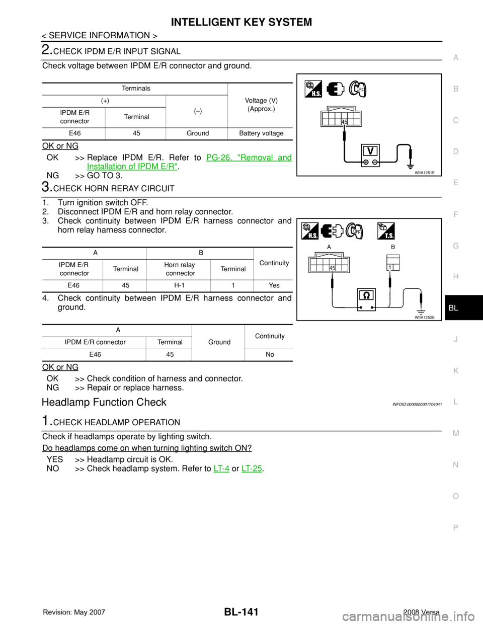
2.CHECK IPDM E/R INPUT SIGNAL
Check voltage between IPDM E/R connector and ground.
OK or NG
OK >> Replace IPDM E/R. Refer to PG-26, "Removal and
Installation of IPDM E/R".
NG >> GO TO 3.
3.CHECK HORN RERAY CIRCUIT
1. Turn ignition switch OFF.
2. Disconnect IPDM E/R and horn relay connector.
3. Check continuity between IPDM E/R harness connector and
horn relay harness connector.
4. Check continuity between IPDM E/R harness connector and
ground.
OK or NG
OK >> Check condition of harness and connector.
NG >> Repair or replace harness.
Headlamp Function CheckINFOID:0000000001704041
1.CHECK HEADLAMP OPERATION
Check if headlamps operate by lighting switch.
Do headlamps come on when turning lighting switch ON?
YES >> Headlamp circuit is OK.
NO >> Check headlamp system. Refer to LT- 4
or LT- 2 5.
Te r m i n a l s
Voltage (V)
(Approx.) (+)
(–)
IPDM E/R
connectorTe r m i n a l
E46 45 Ground Battery voltage
WIIA1251E
AB
Continuity
IPDM E/R
connectorTe r m i n a lHorn relay
connectorTe r m i n a l
E46 45 H-1 1 Yes
A
GroundContinuity
IPDM E/R connector Terminal
E46 45 No
WIIA1252E
Page 580 of 2771
BL-146
< SERVICE INFORMATION >
DOOR
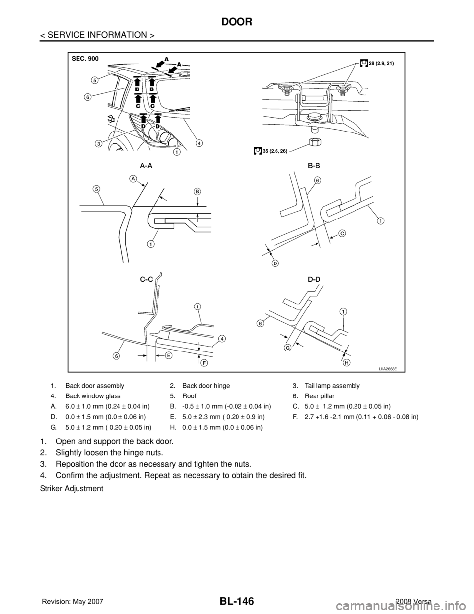
1. Open and support the back door.
2. Slightly loosen the hinge nuts.
3. Reposition the door as necessary and tighten the nuts.
4. Confirm the adjustment. Repeat as necessary to obtain the desired fit.
Striker Adjustment
1. Back door assembly 2. Back door hinge 3. Tail lamp assembly
4. Back window glass 5. Roof 6. Rear pillar
A. 6.0 ± 1.0 mm (0.24 ± 0.04 in) B. -0.5 ± 1.0 mm (-0.02 ± 0.04 in) C. 5.0 ± 1.2 mm (0.20 ± 0.05 in)
D. 0.0 ± 1.5 mm (0.0 ± 0.06 in) E. 5.0 ± 2.3 mm ( 0.20 ± 0.9 in) F. 2.7 +1.6 -2.1 mm (0.11 + 0.06 - 0.08 in)
G. 5.0 ± 1.2 mm ( 0.20 ± 0.05 in) H. 0.0 ± 1.5 mm (0.0 ± 0.06 in)
LIIA2668E
Page 604 of 2771
BL-170
< SERVICE INFORMATION >
TRUNK LID
TRUNK LID
Fitting AdjustmentINFOID:0000000001704065
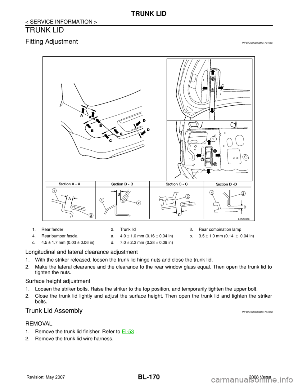
Longitudinal and lateral clearance adjustment
1. With the striker released, loosen the trunk lid hinge nuts and close the trunk lid.
2. Make the lateral clearance and the clearance to the rear window glass equal. Then open the trunk lid to
tighten the nuts.
Surface height adjustment
1. Loosen the striker bolts. Raise the striker to the top position, and temporarily tighten the upper bolt.
2. Close the trunk lid lightly and adjust the surface height. Then open the trunk lid and tighten the striker
bolts.
Trunk Lid AssemblyINFOID:0000000001704066
REMOVAL
1. Remove the trunk lid finisher. Refer to EI-53 .
2. Remove the trunk lid wire harness.
1. Rear fender 2. Trunk lid 3. Rear combination lamp
4. Rear bumper fascia a. 4.0 ± 1.0 mm (0.16 ± 0.04 in) b. 3.5 ± 1.0 mm (0.14 ± 0.04 in)
c. 4.5 ± 1.7 mm (0.03 ± 0.06 in) d. 7.0 ± 2.2 mm (0.28 ± 0.09 in)
LIIA2932E
Page 638 of 2771
BL-204
< SERVICE INFORMATION >
VEHICLE SECURITY (THEFT WARNING) SYSTEM
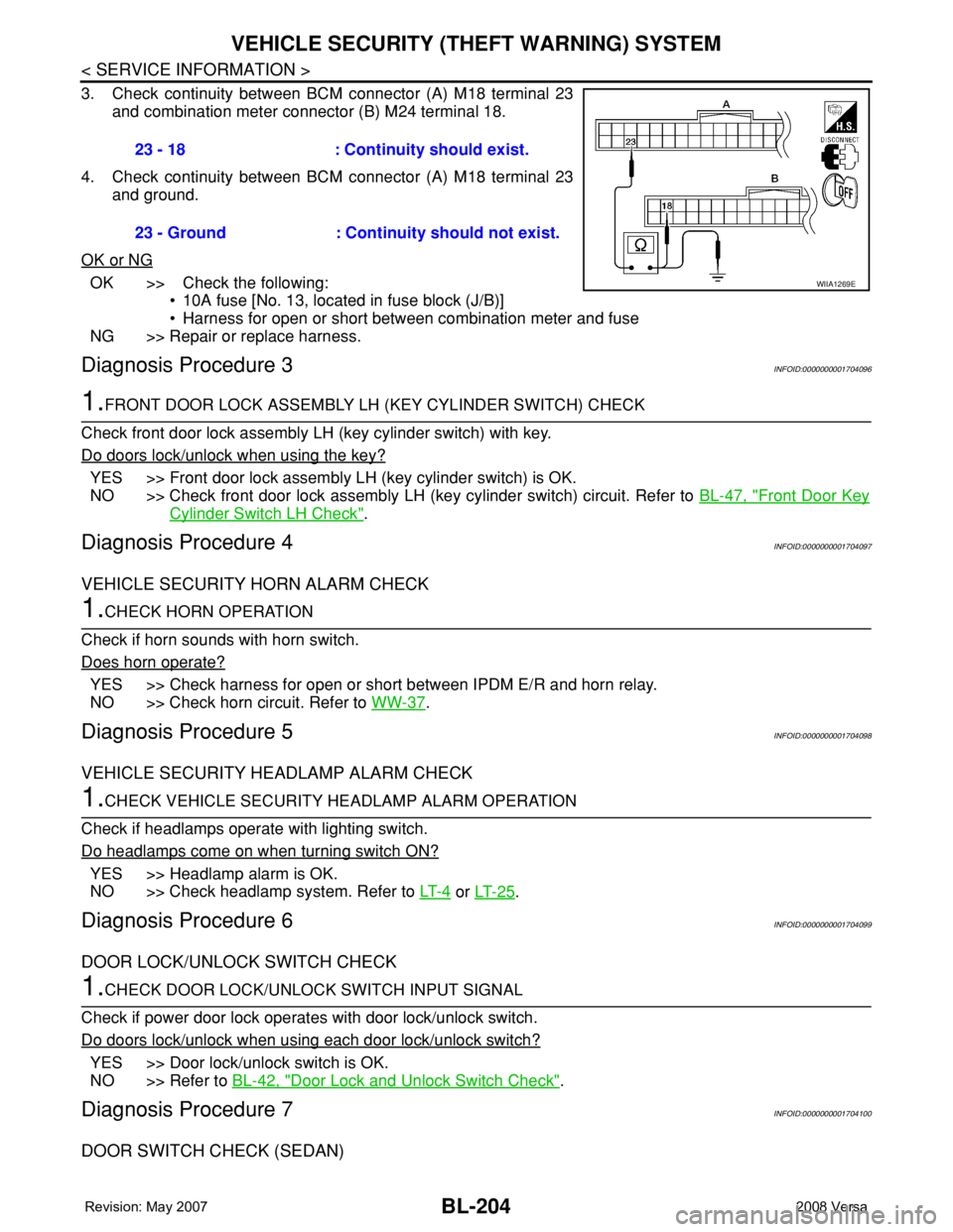
3. Check continuity between BCM connector (A) M18 terminal 23
and combination meter connector (B) M24 terminal 18.
4. Check continuity between BCM connector (A) M18 terminal 23
and ground.
OK or NG
OK >> Check the following:
• 10A fuse [No. 13, located in fuse block (J/B)]
• Harness for open or short between combination meter and fuse
NG >> Repair or replace harness.
Diagnosis Procedure 3INFOID:0000000001704096
1.FRONT DOOR LOCK ASSEMBLY LH (KEY CYLINDER SWITCH) CHECK
Check front door lock assembly LH (key cylinder switch) with key.
Do doors lock/unlock when using the key?
YES >> Front door lock assembly LH (key cylinder switch) is OK.
NO >> Check front door lock assembly LH (key cylinder switch) circuit. Refer to BL-47, "
Front Door Key
Cylinder Switch LH Check".
Diagnosis Procedure 4INFOID:0000000001704097
VEHICLE SECURITY HORN ALARM CHECK
1.CHECK HORN OPERATION
Check if horn sounds with horn switch.
Does horn operate?
YES >> Check harness for open or short between IPDM E/R and horn relay.
NO >> Check horn circuit. Refer to WW-37
.
Diagnosis Procedure 5INFOID:0000000001704098
VEHICLE SECURITY HEADLAMP ALARM CHECK
1.CHECK VEHICLE SECURITY HEADLAMP ALARM OPERATION
Check if headlamps operate with lighting switch.
Do headlamps come on when turning switch ON?
YES >> Headlamp alarm is OK.
NO >> Check headlamp system. Refer to LT- 4
or LT- 2 5.
Diagnosis Procedure 6INFOID:0000000001704099
DOOR LOCK/UNLOCK SWITCH CHECK
1.CHECK DOOR LOCK/UNLOCK SWITCH INPUT SIGNAL
Check if power door lock operates with door lock/unlock switch.
Do doors lock/unlock when using each door lock/unlock switch?
YES >> Door lock/unlock switch is OK.
NO >> Refer to BL-42, "
Door Lock and Unlock Switch Check".
Diagnosis Procedure 7INFOID:0000000001704100
DOOR SWITCH CHECK (SEDAN)
23 - 18 : Continuity should exist.
23 - Ground : Continuity should not exist.
WIIA1269E
Page 652 of 2771

BL-218
< SERVICE INFORMATION >
NATS (NISSAN ANTI-THEFT SYSTEM)
Self-diagnosis related item
• *: When NATS detects trouble, the security indicator lights up while ignition key is in the “ON” position.
SYMPTOM MATRIX CHART 2
Non self-diagnosis related item
*: CONSULT-III self-diagnostic results display screen “no malfunction is detected”.
Diagnosis Procedure 1INFOID:0000000001704112
Self-diagnostic results:
“CHAIN OF ECM-IMMU” displayed on CONSULT-III screen
First perform the “SELF-DIAG RESULTS” in “BCM” with CONSULT-III, then perform the trouble diag-
nosis of malfunction system indicated “SELF-DIAG RESULTS” of “BCM”. Refer to BCS-17, "
CAN Com-
munication Inspection Using CONSULT-III (Self-Diagnosis)" .
1.CONFIRM SELF-DIAGNOSTIC RESULTS
Confirm SELF-DIAGNOSTIC RESULTS “CHAIN OF ECM-IMMU” displayed on CONSULT-III screen.
NOTE:
SYMPTOMDisplayed “SELF-DIAG
RESULTS” on CON-
SULT-III screen.DIAGNOSTIC PROCE-
DURE
(Reference page)SYSTEM
(Malfunctioning part or mode)
• Security indicator
lighting up*
• Engine cannot be
startedCHAIN OF ECM-IMMU
[P1612]PROCEDURE 1
(BL-218
)In rare case, “CHAIN OF ECM-IMMU” might be stored
during key registration procedure, even if the system is
not malfunctioning.
Open circuit in battery voltage line of BCM circuit
Open circuit in ignition line of BCM circuit
Open circuit in ground line of BCM circuit
Open or short circuit between BCM and ECM commu-
nication line
ECM
BCM
CHAIN OF IMMU-KEY
[P1614]PROCEDURE 2
(BL-220
)Malfunction of key ID chip
Communication line between ANT/ AMP and BCM:
Open circuit or short circuit of battery voltage line or
ground line
Open circuit in power source line of ANT/ AMP circuit
Open circuit in ground line of ANT/ AMP circuit
NATS antenna amp.
BCM
ID DISCORD, IMM-
ECM
[P1611]PROCEDURE 3
(BL-221
)System initialization has not yet been completed.
ECM
LOCK MODE
[P1610]PROCEDURE 5
(BL-223
)When the starting operation is carried out five or more
times consecutively under the following conditions,
NATS will shift the mode to one which prevents the en-
gine from being started.
• Unregistered ignition key is used.
• BCM or ECM’s malfunctioning.
Security indicator
lighting up*DON'T ERASE BE-
FORE CHECKING
ENG DIAGWORK FLOW
(BL-215
)Engine trouble data and NATS trouble data have been
detected in ECM
SYMPTOMDIAGNOSTIC PROCEDURE
(Reference page)SYSTEM
(Malfunctioning part or mode)
Security indicator does not light up*.PROCEDURE 4
(BL-222
)Security indictor.
Open circuit between Fuse and BCM
BCM
Page 656 of 2771
BL-222
< SERVICE INFORMATION >
NATS (NISSAN ANTI-THEFT SYSTEM)
“ID DISCORD IMM-ECM”:
Registered ID of BCM is in discord with that of ECM.
Is
“ID DISCORD IMM-ECM” displayed?
Ye s > > G O T O 2 .
No >> GO TO BL-217, "
Trouble Diagnosis" .
2.PERFORM INITIALIZATION WITH CONSULT-III
Perform initialization with CONSULT-III. Re-register all NATS ignition key IDs.
For initialization, refer to “CONSULT-III Operation Manual NATS”.
NOTE:
If the initialization is not completed or malfunctions, CONSULT-III shows message on the screen.
Can the system be initialized?
Yes >> • Start engine. (END)
• (System initialization had not been completed.)
No >> ECM is malfunctioning.
• Replace ECM.
• Perform initialization with CONSULT-III
For initialization, refer to “CONSULT-III Operation Manual NATS”
Diagnosis Procedure 4INFOID:0000000001704115
“COMBINATION METER (SECURITY) DOES NOT LIGHT UP”
1.CHECK FUSE
Check 10A fuse [No.13, located in the fuse block (J/B)]
OK or NG
OK >> GO TO 2.
NG >> Replace fuse.
2.CHECK COMBINATION METER (SECURITY)
1. Install 10A fuse.
2. Start engine and turn ignition switch OFF.
3. Check if the combination meter (security) lights up.
OK or NG
OK >> INSPECTION END.
NG >> GO TO 3.
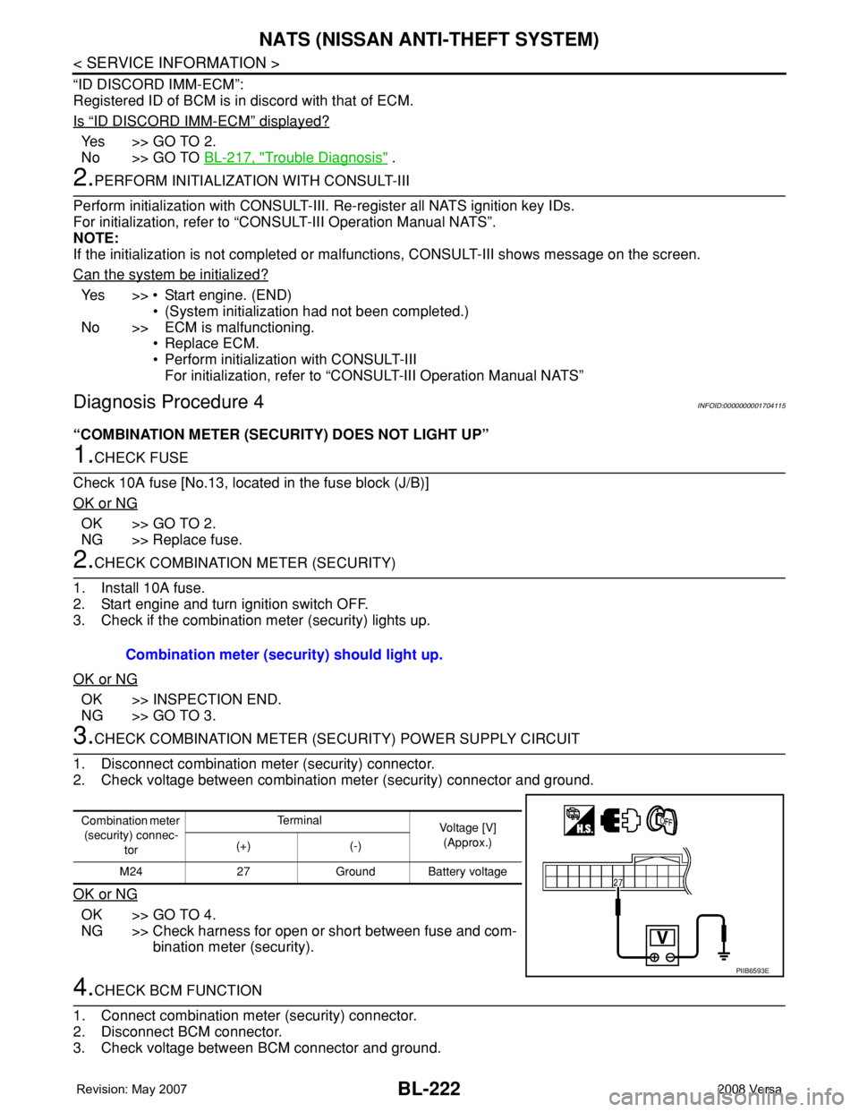
3.CHECK COMBINATION METER (SECURITY) POWER SUPPLY CIRCUIT
1. Disconnect combination meter (security) connector.
2. Check voltage between combination meter (security) connector and ground.
OK or NG
OK >> GO TO 4.
NG >> Check harness for open or short between fuse and com-
bination meter (security).
4.CHECK BCM FUNCTION
1. Connect combination meter (security) connector.
2. Disconnect BCM connector.
3. Check voltage between BCM connector and ground. Combination meter (security) should light up.
Combination meter
(security) connec-
torTe r m i n a l
Voltage [V]
(Approx.)
(+) (-)
M24 27 Ground Battery voltage
PIIB6593E
Page 702 of 2771
BL-268
< SERVICE INFORMATION >
BODY REPAIR
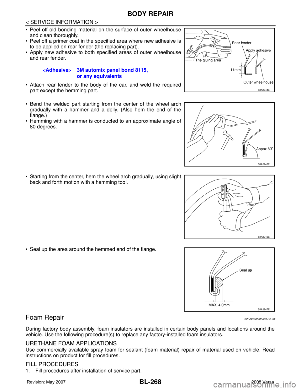
• Peel off old bonding material on the surface of outer wheelhouse
and clean thoroughly.
• Peel off a primer coat in the specified area where new adhesive is
to be applied on rear fender (the replacing part).
• Apply new adhesive to both specified areas of outer wheelhouse
and rear fender.
• Attach rear fender to the body of the car, and weld the required
part except the hemming part.
• Bend the welded part starting from the center of the wheel arch
gradually with a hammer and a dolly. (Also hem the end of the
flange.)
• Hemming with a hammer is conducted to an approximate angle of
80 degrees.
• Starting from the center, hem the wheel arch gradually, using slight
back and forth motion with a hemming tool.
• Seal up the area around the hemmed end of the flange.
Foam RepairINFOID:0000000001704126
During factory body assembly, foam insulators are installed in certain body panels and locations around the
vehicle. Use the following procedure(s) to replace any factory-installed foam insulators.
URETHANE FOAM APPLICATIONS
Use commercially available spray foam for sealant (foam material) repair of material used on vehicle. Read
instructions on product for fill procedures.
FILL PROCEDURES
1. Fill procedures after installation of service part.
or any equivalents
SIIA2244E
SIIA2245E
SIIA2246E
SIIA2247E
Page 767 of 2771
![NISSAN LATIO 2008 Service Repair Manual BRC-2
< SERVICE INFORMATION >[ABS]
PRECAUTIONS
SERVICE INFORMATION
PRECAUTIONS
Precaution for Supplemental Restraint System (SRS) "AIR BAG" and "SEAT BELT
PRE-TENSIONER"
INFOID:000000 NISSAN LATIO 2008 Service Repair Manual BRC-2
< SERVICE INFORMATION >[ABS]
PRECAUTIONS
SERVICE INFORMATION
PRECAUTIONS
Precaution for Supplemental Restraint System (SRS) "AIR BAG" and "SEAT BELT
PRE-TENSIONER"
INFOID:000000](/manual-img/5/57360/w960_57360-766.png)
BRC-2
< SERVICE INFORMATION >[ABS]
PRECAUTIONS
SERVICE INFORMATION
PRECAUTIONS
Precaution for Supplemental Restraint System (SRS) "AIR BAG" and "SEAT BELT
PRE-TENSIONER"
INFOID:0000000001703818
The Supplemental Restraint System such as “AIR BAG” and “SEAT BELT PRE-TENSIONER”, used along
with a front seat belt, helps to reduce the risk or severity of injury to the driver and front passenger for certain
types of collision. This system includes seat belt switch inputs and dual stage front air bag modules. The SRS
system uses the seat belt switches to determine the front air bag deployment, and may only deploy one front
air bag, depending on the severity of a collision and whether the front occupants are belted or unbelted.
Information necessary to service the system safely is included in the SRS and SB section of this Service Man-
ual.
WARNING:
• To avoid rendering the SRS inoperative, which could increase the risk of personal injury or death in
the event of a collision which would result in air bag inflation, all maintenance must be performed by
an authorized NISSAN/INFINITI dealer.
• Improper maintenance, including incorrect removal and installation of the SRS, can lead to personal
injury caused by unintentional activation of the system. For removal of Spiral Cable and Air Bag
Module, see the SRS section.
• Do not use electrical test equipment on any circuit related to the SRS unless instructed to in this
Service Manual. SRS wiring harnesses can be identified by yellow and/or orange harnesses or har-
ness connectors.
Precaution for Brake SystemINFOID:0000000001703819
CAUTION:
• Refer to MA-10
for recommended brake fluid.
• Never reuse drained brake fluid.
• Be careful not to splash brake fluid on painted areas; it may cause paint damage. If brake fluid is
splashed on painted areas, wash it away with water immediately.
• To clean or wash all parts of master cylinder and disc brake caliper, use clean brake fluid.
• Never use mineral oils such as gasoline or kerosene. They will ruin rubber parts of the hydraulic sys-
tem.
• Use flare nut wrench when removing and installing brake
tube.
• If a brake fluid leak is found, the part must be disassembled
without fail. Then it has to be replaced with a new one if a
defect exists.
• Turn the ignition switch OFF and remove the connector of the
ABS actuator and electric unit (control unit) or the battery ter-
minal before performing the work.
• Always torque brake lines when installing.
• Burnish the brake contact surfaces after refinishing or replac-
ing rotors, after replacing pads, or if a soft pedal occurs at
very low mileage. Refer to BR-28, "
Brake Burnishing Proce-
dure".
WARNING:
• Clean brake pads and shoes with a waste cloth, then wipe with a dust collector.
Precaution for Brake ControlINFOID:0000000001703821
• During ABS operation, the brake pedal may vibrate lightly and a mechanical noise may be heard. This is
normal.
• Just after starting the vehicle, the brake pedal may vibrate or motor operating noises may be heard from
engine compartment. This is normal due to the self check operation.
• Stopping distance may be longer than that of vehicles without ABS when vehicle drives on rough, gravel, or
snow-covered (fresh, deep snow) roads.
SBR686C