Page 295 of 2771
REPAIR FOR COMPONENT PARTS
AT-283
< SERVICE INFORMATION >
D
E
F
G
H
I
J
K
L
MA
B
AT
N
O
P
4. Set Tool A on spring retainer assembly, and install snap ring (1)
while compressing spring retainer assembly.
CAUTION:
Set SST directly over return springs.
5. Install dish plates, driven plates, drive plates and retaining plate.
(1): Snap ring
(2): Retaining plate
(3): Drive plate
(4): Driven plate
(5): Dish plate
Drive plate/Driven plate: 2/2
CAUTION:
Be careful with the order of plates.
NOTE:
Install two dish plates fitting each installation direction with
reverse clutch drum groove displaced slightly.
6. Install snap ring (1) using a flat-bladed screwdriver A.Tool number: KV31103200 (J-39186)
SCIA7988E
SCIA7003J
SAT170D
SCIA7024J
Page 311 of 2771
REPAIR FOR COMPONENT PARTS
AT-299
< SERVICE INFORMATION >
D
E
F
G
H
I
J
K
L
MA
B
AT
N
O
P
NOTE:
Install two dish plates fitting each installation direction with
groove displaced slightly.
6. Install snap ring (1) using a flat-bladed screwdriver A.
7. Measure clearance between retaining plate and snap ring. If not
within allowable limit, select proper retaining plate (front side).
Refer to “Parts Information” for retaining plate selection.
8. Check operation of low & reverse brake. Refer to "DISASSEM-
BLY".
Rear Internal Gear and Forward Clutch HubINFOID:0000000001703387
COMPONENTS
SAT254E
SCIA7039E
Specified clearance
Standard and allowable limit:
Refer to AT-343, "
Clutches and Brakes".
SAT246D
SCIA5880J
Page 332 of 2771
AT-320
< SERVICE INFORMATION >
ASSEMBLY
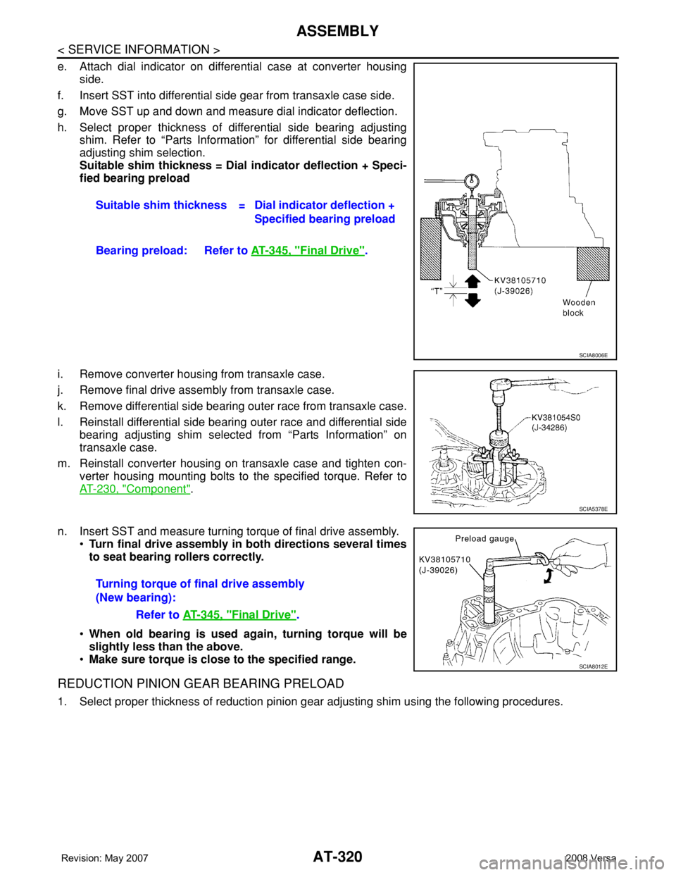
e. Attach dial indicator on differential case at converter housing
side.
f. Insert SST into differential side gear from transaxle case side.
g. Move SST up and down and measure dial indicator deflection.
h. Select proper thickness of differential side bearing adjusting
shim. Refer to “Parts Information” for differential side bearing
adjusting shim selection.
Suitable shim thickness = Dial indicator deflection + Speci-
fied bearing preload
i. Remove converter housing from transaxle case.
j. Remove final drive assembly from transaxle case.
k. Remove differential side bearing outer race from transaxle case.
l. Reinstall differential side bearing outer race and differential side
bearing adjusting shim selected from “Parts Information” on
transaxle case.
m. Reinstall converter housing on transaxle case and tighten con-
verter housing mounting bolts to the specified torque. Refer to
AT-230, "
Component".
n. Insert SST and measure turning torque of final drive assembly.
•Turn final drive assembly in both directions several times
to seat bearing rollers correctly.
•When old bearing is used again, turning torque will be
slightly less than the above.
•Make sure torque is close to the specified range.
REDUCTION PINION GEAR BEARING PRELOAD
1. Select proper thickness of reduction pinion gear adjusting shim using the following procedures.Suitable shim thickness = Dial indicator deflection +
Specified bearing preload
Bearing preload: Refer to AT-345, "
Final Drive".
SCIA8006E
SCIA5378E
Turning torque of final drive assembly
(New bearing):
Refer to AT-345, "
Final Drive".
SCIA8012E
Page 337 of 2771
ASSEMBLY
AT-325
< SERVICE INFORMATION >
D
E
F
G
H
I
J
K
L
MA
B
AT
N
O
P
• Completely remove all moisture, oil and old sealant, etc. from the transaxle case and side cover
mounting surfaces.
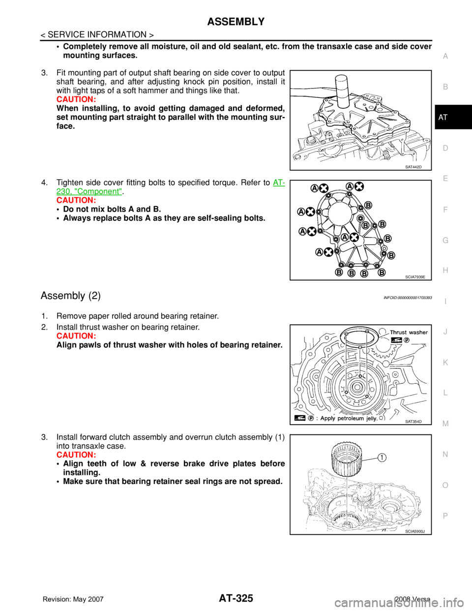
3. Fit mounting part of output shaft bearing on side cover to output
shaft bearing, and after adjusting knock pin position, install it
with light taps of a soft hammer and things like that.
CAUTION:
When installing, to avoid getting damaged and deformed,
set mounting part straight to parallel with the mounting sur-
face.
4. Tighten side cover fitting bolts to specified torque. Refer to AT-
230, "Component".
CAUTION:
• Do not mix bolts A and B.
• Always replace bolts A as they are self-sealing bolts.
Assembly (2)INFOID:0000000001703393
1. Remove paper rolled around bearing retainer.
2. Install thrust washer on bearing retainer.
CAUTION:
Align pawls of thrust washer with holes of bearing retainer.
3. Install forward clutch assembly and overrun clutch assembly (1)
into transaxle case.
CAUTION:
• Align teeth of low & reverse brake drive plates before
installing.
• Make sure that bearing retainer seal rings are not spread.
SAT442D
SCIA7939E
SAT354D
SCIA5900J
Page 381 of 2771
AV-22
< SERVICE INFORMATION >
AUDIO
Power Supply Circuit Inspection
INFOID:0000000001704663
1.CHECK FUSE
Check that the following fuses of the subwoofer (premium system) and audio unit are not blown.
OK or NG
OK >> GO TO 2.
NG >> If fuse is blown, be sure to eliminate cause of blown fuse before installing new fuse. Refer to PG-
3 .
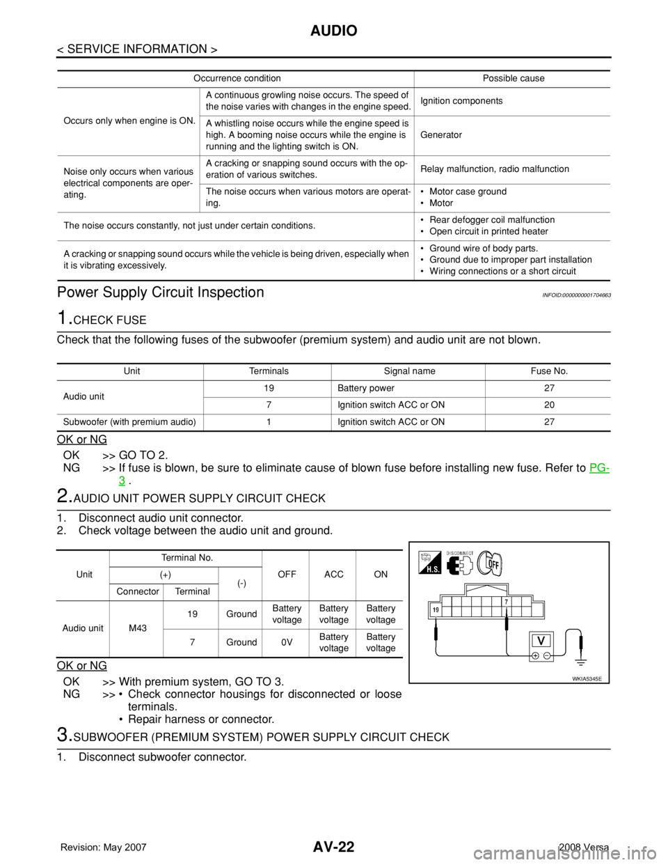
2.AUDIO UNIT POWER SUPPLY CIRCUIT CHECK
1. Disconnect audio unit connector.
2. Check voltage between the audio unit and ground.
OK or NG
OK >> With premium system, GO TO 3.
NG >> • Check connector housings for disconnected or loose
terminals.
• Repair harness or connector.
3.SUBWOOFER (PREMIUM SYSTEM) POWER SUPPLY CIRCUIT CHECK
1. Disconnect subwoofer connector.
Occurrence condition Possible cause
Occurs only when engine is ON.A continuous growling noise occurs. The speed of
the noise varies with changes in the engine speed.Ignition components
A whistling noise occurs while the engine speed is
high. A booming noise occurs while the engine is
running and the lighting switch is ON.Generator
Noise only occurs when various
electrical components are oper-
ating.A cracking or snapping sound occurs with the op-
eration of various switches.Relay malfunction, radio malfunction
The noise occurs when various motors are operat-
ing.• Motor case ground
• Motor
The noise occurs constantly, not just under certain conditions.• Rear defogger coil malfunction
• Open circuit in printed heater
A cracking or snapping sound occurs while the vehicle is being driven, especially when
it is vibrating excessively.• Ground wire of body parts.
• Ground due to improper part installation
• Wiring connections or a short circuit
Unit Terminals Signal name Fuse No.
Audio unit19 Battery power 27
7 Ignition switch ACC or ON 20
Subwoofer (with premium audio) 1 Ignition switch ACC or ON 27
UnitTe r m i n a l N o .
OFF ACC ON (+)
(-)
Connector Terminal
Audio unit M4319 GroundBattery
voltageBattery
voltageBattery
voltage
7Ground0VBattery
voltageBattery
voltage
WKIA5345E
Page 419 of 2771
BCM (BODY CONTROL MODULE)
BCS-3
< SERVICE INFORMATION >
C
D
E
F
G
H
I
J
L
MA
B
BCS
N
O
P
BCM (BODY CONTROL MODULE)
System DescriptionINFOID:0000000001704584
BCM (body control module) controls the operation of various electrical units installed on the vehicle.
BCM FUNCTION
BCM has a combination switch reading function for reading the operation of combination switches (light, wiper,
washer, turn signal) in addition to the function for controlling the operation of various electrical components.
Also, it functions as an interface that receives signals from the front air control, and sends signals to ECM
using CAN communication.
COMBINATION SWITCH READING FUNCTION
1. Description
• BCM reads combination switch (light, wiper) status, and controls various electrical components accord-
ing to the results.
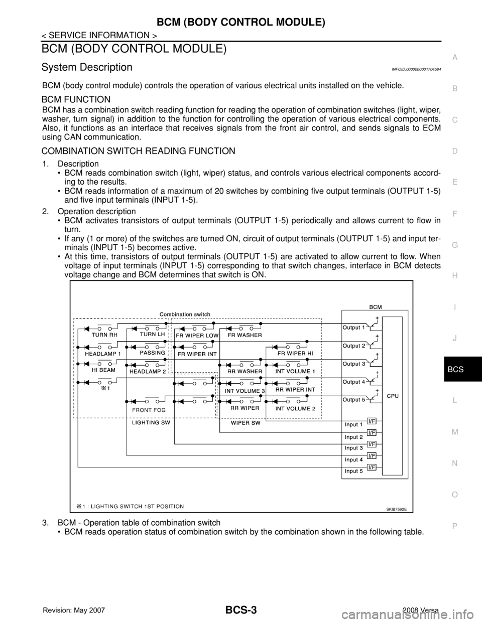
• BCM reads information of a maximum of 20 switches by combining five output terminals (OUTPUT 1-5)
and five input terminals (INPUT 1-5).
2. Operation description
• BCM activates transistors of output terminals (OUTPUT 1-5) periodically and allows current to flow in
turn.
• If any (1 or more) of the switches are turned ON, circuit of output terminals (OUTPUT 1-5) and input ter-
minals (INPUT 1-5) becomes active.
• At this time, transistors of output terminals (OUTPUT 1-5) are activated to allow current to flow. When
voltage of input terminals (INPUT 1-5) corresponding to that switch changes, interface in BCM detects
voltage change and BCM determines that switch is ON.
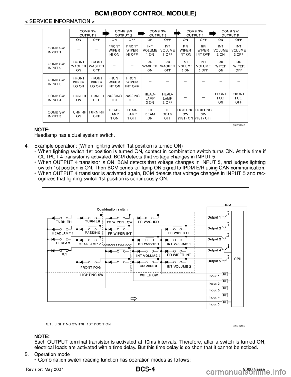
3. BCM - Operation table of combination switch
• BCM reads operation status of combination switch by the combination shown in the following table.
SKIB7592E
Page 420 of 2771
BCS-4
< SERVICE INFORMATION >
BCM (BODY CONTROL MODULE)
NOTE:
Headlamp has a dual system switch.
4. Example operation: (When lighting switch 1st position is turned ON)
• When lighting switch 1st position is turned ON, contact in combination switch turns ON. At this time if
OUTPUT 4 transistor is activated, BCM detects that voltage changes in INPUT 5.
• When OUTPUT 4 transistor is ON, BCM detects that voltage changes in INPUT 5, and judges lighting
switch 1st position is ON. Then BCM sends tail lamp ON signal to IPDM E/R using CAN communication.
• When OUTPUT 4 transistor is activated again, BCM detects that voltage changes in INPUT 5 and rec-
ognizes that lighting switch 1st position is continuously ON.
NOTE:
Each OUTPUT terminal transistor is activated at 10ms intervals. Therefore, after a switch is turned ON,
electrical loads are activated with a time delay. But this time delay is so short that it cannot be noticed.
5. Operation mode
• Combination switch reading function has operation modes as follows:
SKIB7614E
SKIB7615E
Page 421 of 2771
BCM (BODY CONTROL MODULE)
BCS-5
< SERVICE INFORMATION >
C
D
E
F
G
H
I
J
L
MA
B
BCS
N
O
P
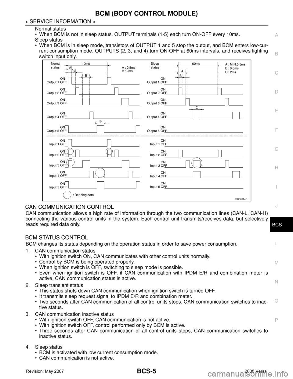
Normal status
• When BCM is not in sleep status, OUTPUT terminals (1-5) each turn ON-OFF every 10ms.
Sleep status
• When BCM is in sleep mode, transistors of OUTPUT 1 and 5 stop the output, and BCM enters low-cur-
rent-consumption mode. OUTPUTS (2, 3, and 4) turn ON-OFF at 60ms intervals, and receives lighting
switch input only.
CAN COMMUNICATION CONTROL
CAN communication allows a high rate of information through the two communication lines (CAN-L, CAN-H)
connecting the various control units in the system. Each control unit transmits/receives data, but selectively
reads required data only.
BCM STATUS CONTROL
BCM changes its status depending on the operation status in order to save power consumption.
1. CAN communication status
• With ignition switch ON, CAN communicates with other control units normally.
• Control by BCM is being operated properly.
• When ignition switch is OFF, switching to sleep mode is possible.
• Even when ignition switch is OFF, if CAN communication with IPDM E/R and combination meter is
active, CAN communication status is active.
2. Sleep transient status
• This status shuts down CAN communication when ignition switch is turned OFF.
• It transmits sleep request signal to IPDM E/R and combination meter.
• Two seconds after CAN communication of all control units stops, CAN communication switches to inac-
tive status.
3. CAN communication inactive status
• With ignition switch OFF, CAN communication is not active.
• With ignition switch OFF, control performed only by BCM is active.
• Three seconds after CAN communication of all control units stops, CAN communication switches to
inactive status.
4. Sleep status
• BCM is activated with low current consumption mode.
• CAN communication is not active.
PKIB6124E