2008 NISSAN LATIO heater
[x] Cancel search: heaterPage 1177 of 2771
![NISSAN LATIO 2008 Service Repair Manual TROUBLE DIAGNOSIS
EC-103
< SERVICE INFORMATION >
C
D
E
F
G
H
I
J
K
L
MA
EC
N
P O
4 P Throttle control motor (Close)[Ignition switch: ON]
• Engine stopped
• Shift lever: D (A/T, CVT), 1st (M/T)
• NISSAN LATIO 2008 Service Repair Manual TROUBLE DIAGNOSIS
EC-103
< SERVICE INFORMATION >
C
D
E
F
G
H
I
J
K
L
MA
EC
N
P O
4 P Throttle control motor (Close)[Ignition switch: ON]
• Engine stopped
• Shift lever: D (A/T, CVT), 1st (M/T)
•](/manual-img/5/57360/w960_57360-1176.png)
TROUBLE DIAGNOSIS
EC-103
< SERVICE INFORMATION >
C
D
E
F
G
H
I
J
K
L
MA
EC
N
P O
4 P Throttle control motor (Close)[Ignition switch: ON]
• Engine stopped
• Shift lever: D (A/T, CVT), 1st (M/T)
• Accelerator pedal: Fully releasedApproximately 1.8V
5GHeated oxygen sensor 2
heater[Engine is running]
• Engine speed: Below 3,600 rpm after the
following conditions are met.
- Engine: After warming up
- Keeping the engine speed between 3,500
and 4,000 rpm for 1 minute and at idle for 1
minute under no load.Approximately 10V
[Ignition switch: ON]
• Engine stopped
[Engine is running]
• Engine speed: Above 3,600 rpm.BATTERY VOLTAGE
(11 - 14V)
9PEVAP canister purge volume
control solenoid valve[Engine is running]
• Idle speed
• Accelerator pedal: Not depressed even
slightly, after engine starting.BATTERY VOLTAGE
(11 - 14V)
[Engine is running]
• Engine speed: About 2,000 rpm (More than
100 seconds after starting engine)Approximately 10V
10
11B
BECM ground[Engine is running]
• Idle speedBody ground
13 L Tachometer signal[Engine is running]
•Warm-up condition
• Idle speed
NOTE:
The pulse cycle changes depending on rpm
at idle.3 - 5V
[Engine is running]
• Warm-up condition
• Engine speed: 2,000 rpm.3 - 5V TERMI-
NAL
NO.WIRE
COLORITEM CONDITION DATA (DC Voltage)
PBIA8149J
PBIA8148J
PBIB0050E
PBIB0520E
PBIA8164J
PBIA8165J
Page 1185 of 2771

TROUBLE DIAGNOSIS
EC-111
< SERVICE INFORMATION >
C
D
E
F
G
H
I
J
K
L
MA
EC
N
P O
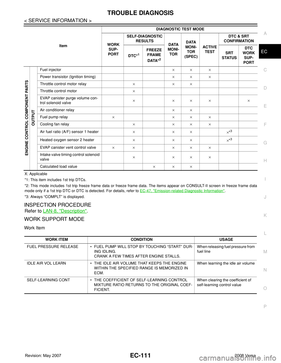
X: Applicable
*1: This item includes 1st trip DTCs.
*2: This mode includes 1st trip freeze frame data or freeze frame data. The items appear on CONSULT-II screen in freeze frame data
mode only if a 1st trip DTC or DTC is detected. For details, refer to EC-47, "
Emission-related Diagnostic Information".
*3: Always “COMPLT” is displayed.
INSPECTION PROCEDURE
Refer to LAN-8, "Description".
WORK SUPPORT MODE
Work Item
ENGINE CONTROL COMPONENT PARTS
OUTPUT
Fuel injector×× ×
Power transistor (Ignition timing)×× ×
Throttle control motor relay×××
Throttle control motor×
EVAP canister purge volume con-
trol solenoid valve×××××
Air conditioner relay××
Fuel pump relay××××
Cooling fan relay××××
Air fuel ratio (A/F) sensor 1 heater×××
×*
3
Heated oxygen sensor 2 heater×××
×*3
EVAP canister vent control valve×× ×××
Intake valve timing control solenoid
valve××××
Calculated load value××× ItemDIAGNOSTIC TEST MODE
WORK
SUP-
PORTSELF-DIAGNOSTIC
RESULTS
DATA
MONI-
TORDATA
MONI-
TOR
(SPEC)ACTIVE
TESTDTC & SRT
CONFIRMATION
DTC*
1 FREEZE
FRAME
DATA*
2
SRT
STATUSDTC
WORK
SUP-
PORT
WORK ITEM CONDITION USAGE
FUEL PRESSURE RELEASE • FUEL PUMP WILL STOP BY TOUCHING “START” DUR-
ING IDLING.
CRANK A FEW TIMES AFTER ENGINE STALLS.When releasing fuel pressure from
fuel line
IDLE AIR VOL LEARN • THE IDLE AIR VOLUME THAT KEEPS THE ENGINE
WITHIN THE SPECIFIED RANGE IS MEMORIZED IN
ECM.When learning the idle air volume
SELF-LEARNING CONT • THE COEFFICIENT OF SELF-LEARNING CONTROL
MIXTURE RATIO RETURNS TO THE ORIGINAL COEF-
FICIENT.When clearing the coefficient of
self-learning control value
Page 1188 of 2771
![NISSAN LATIO 2008 Service Repair Manual EC-114
< SERVICE INFORMATION >
TROUBLE DIAGNOSIS
FUEL T/TMP SE [°C]
or [°F]ו The fuel temperature (determined by the signal
voltage of the fuel tank temperature sensor) is
displayed.
INT/A TE NISSAN LATIO 2008 Service Repair Manual EC-114
< SERVICE INFORMATION >
TROUBLE DIAGNOSIS
FUEL T/TMP SE [°C]
or [°F]ו The fuel temperature (determined by the signal
voltage of the fuel tank temperature sensor) is
displayed.
INT/A TE](/manual-img/5/57360/w960_57360-1187.png)
EC-114
< SERVICE INFORMATION >
TROUBLE DIAGNOSIS
FUEL T/TMP SE [°C]
or [°F]ו The fuel temperature (determined by the signal
voltage of the fuel tank temperature sensor) is
displayed.
INT/A TEMP SE
[°C] or [°F]×ו The intake air temperature (determined by the
signal voltage of the intake air temperature
sensor) is indicated.
EVAP SYS PRES [V]ו The signal voltage of EVAP control system
pressure sensor is displayed.
FUEL LEVEL SE [V]ו The signal voltage of the fuel level sensor is
displayed.
START SIGNAL
[ON/OFF]×ו Indicates start signal status [ON/OFF] comput-
ed by the ECM according to the signals of en-
gine speed and battery voltage.• After starting the engine, [OFF] is
displayed regardless of the starter
signal.
CLSD THL POS
[ON/OFF]×ו Indicates idle position [ON/OFF] computed by
the ECM according to the accelerator pedal po-
sition sensor signal.
AIR COND SIG
[ON/OFF]×ו Indicates [ON/OFF] condition of the air condi-
tioner switch as determined by the air condi-
tioner signal.
P/N POSI SW
[ON/OFF]×ו Indicates [ON/OFF] condition from the park/
neutral position (PNP) switch signal.
PW/ST SIGNAL [ON/
OFF]×ו [ON/OFF] condition of the power steering sys-
tem (determined by the signal sent from EPS
control unit) is indicated.
LOAD SIGNAL
[ON/OFF]×ו Indicates [ON/OFF] condition from the electri-
cal load signal.
ON: Rear window defogger switch is ON and/
or lighting switch is in 2nd position.
OFF: Both rear window defogger switch and
lighting switch are OFF.
IGNITION SW
[ON/OFF]ו Indicates [ON/OFF] condition from ignition
switch.
HEATER FAN SW
[ON/OFF]ו Indicates [ON/OFF] condition from the heater
fan switch signal.
BRAKE SW
[ON/OFF]ו Indicates [ON/OFF] condition from the stop
lamp switch signal.
INJ PULSE-B1
[msec]ו Indicates the actual fuel injection pulse width
compensated by ECM according to the input
signals.• When the engine is stopped, a
certain computed value is indicat-
ed.
IGN TIMING [BTDC]• Indicates the ignition timing computed by ECM
according to the input signals.• When the engine is stopped, a
certain value is indicated.
CAL/LD VALUE [%]• “Calculated load value” indicates the value of
the current airflow divided by peak airflow.
MASS AIRFLOW
[g·m/s]• Indicates the mass airflow computed by ECM
according to the signal voltage of the mass air
flow sensor.
PURG VOL C/V [%]• Indicates the EVAP canister purge volume con-
trol solenoid valve control value computed by
the ECM according to the input signals.
• The opening becomes larger as the value in-
creases.
INT/V TIM (B1) [°CA]• Indicates [°CA] of intake camshaft advanced
angle. Monitored item [Unit]ECM IN-
PUT SIG-
NALSMAIN
SIG-
NALSDescription Remarks
Page 1189 of 2771
![NISSAN LATIO 2008 Service Repair Manual TROUBLE DIAGNOSIS
EC-115
< SERVICE INFORMATION >
C
D
E
F
G
H
I
J
K
L
MA
EC
N
P OINT/V SOL (B1) [%]• The control value of the intake valve timing
control solenoid valve (determined by ECM ac-
cordin NISSAN LATIO 2008 Service Repair Manual TROUBLE DIAGNOSIS
EC-115
< SERVICE INFORMATION >
C
D
E
F
G
H
I
J
K
L
MA
EC
N
P OINT/V SOL (B1) [%]• The control value of the intake valve timing
control solenoid valve (determined by ECM ac-
cordin](/manual-img/5/57360/w960_57360-1188.png)
TROUBLE DIAGNOSIS
EC-115
< SERVICE INFORMATION >
C
D
E
F
G
H
I
J
K
L
MA
EC
N
P OINT/V SOL (B1) [%]• The control value of the intake valve timing
control solenoid valve (determined by ECM ac-
cording to the input signal) is indicated.
• The advance angle becomes larger as the val-
ue increases
AIR COND RLY
[ON/OFF]ו The air conditioner relay control condition (de-
termined by ECM according to the input sig-
nals) is indicated.
FUEL PUMP RLY
[ON/OFF]ו Indicates the fuel pump relay control condition
determined by ECM according to the input sig-
nals.
VENT CONT/V [ON/
OFF]• The control condition of the EVAP canister vent
control valve (determined by ECM according to
the input signals) is indicated.
ON: Closed
OFF: Open
THRTL RELAY
[ON/OFF]ו Indicates the throttle control motor relay control
condition determined by the ECM according to
the input signals.
COOLING FAN
[HI/LOW/OFF]ו Indicates the condition of the cooling fan (de-
termined by ECM according to the input sig-
nals).
HI: High speed operation
LOW: Low speed operation
OFF: Stop
HO2S2 HTR (B1)
[ON/OFF]• Indicates [ON/OFF] condition of heated oxygen
sensor 2 heater determined by ECM according
to the input signals.
I/P PULLY SPD
[rpm]• Indicates the engine speed computed from the
turbine revolution sensor signal.
VEHICLE SPEED
[km/h] or [MPH]ו The vehicle speed computed from the vehicle
speed signal sent from TCM is displayed.
IDL A/V LEARN
[YET/CMPLT]• Display the condition of idle air volume learning
YET: Idle Air Volume Learning has not been
performed yet.
CMPLT: Idle Air Volume Learning has already
been performed successfully.
TRVL AFTER MIL
[km] or [mile]• Distance traveled while MIL is activated.
A/F S1 HTR (B1) [%]• Indicates A/F sensor 1 heater control value
computed by ECM according to the input sig-
nals.
• The current flow to the heater becomes larger
as the value increases.
AC PRESS SEN [V]ו The signal voltage from the refrigerant pres-
sure sensor is displayed.
VHCL SPEED SE
[km/h] or [MPH]• The vehicle speed computed from the vehicle
speed signal sent from TCM is displayed.
SET VHCL SPD
[km/h] or [MPH]• The preset vehicle speed is displayed.
MAIN SW
[ON/OFF]• Indicates [ON/OFF] condition from MAIN
switch signal.
CANCEL SW
[ON/OFF]• Indicates [ON/OFF] condition from CANCEL
switch signal. Monitored item [Unit]ECM IN-
PUT SIG-
NALSMAIN
SIG-
NALSDescription Remarks
Page 1196 of 2771

EC-122
< SERVICE INFORMATION >
TROUBLE DIAGNOSIS
THRTL SEN 1
THRTL SEN 2*• Ignition switch: ON
(Engine stopped)Accelerator pedal: Fully released More than 0.36V
• Shift lever: D (A/T, CVT),
1st (M/T)Accelerator pedal: Fully depressed Less than 4.75V
START SIGNAL • Ignition switch: ON → START → ON OFF → ON → OFF
CLSD THL POS • Ignition switch: ONAccelerator pedal: Fully released ON
Accelerator pedal: Slightly depressed OFF
AIR COND SIG• Engine: After warming up, idle the
engineAir conditioner switch: OFF OFF
Air conditioner switch: ON
(Compressor operates.)ON
P/N POSI SW • Ignition switch: ONShift lever: P or N (A/T, CVT),
Neutral (M/T)ON
Shift lever: Except above OFF
PW/ST SIGNAL• Engine: After warming up, idle the
engineSteering wheel: Not being turned OFF
Steering wheel: Being turned ON
LOAD SIGNAL • Ignition switch: ONRear window defogger switch: ON
and/or Lighting switch: 2ndON
Rear window defogger switch and light-
ing switch: OFFOFF
IGNITION SW • Ignition switch: ON → OFF → ON ON → OFF → ON
HEATER FAN SW • Ignition switch: ONHeater fan: Operating ON
Heater fan: Not operating OFF
BRAKE SW • Ignition switch: ONBrake pedal: Fully released OFF
Brake pedal: Slightly depressed ON
INJ PULSE-B1• Engine: After warming up
• Air conditioner switch: OFF
• Shift lever: P or N (A/T, CVT),
Neutral (M/T)
•No loadIdle 2.0 - 3.0 msec
2,000 rpm 1.9 - 2.9 msec
IGN TIMING• Engine: After warming up
• Air conditioner switch: OFF
• Shift lever: P or N (A/T, CVT),
Neutral (M/T)
•No loadIdle 8° - 18° BTDC
2,000 rpm 25° - 45° BTDC
CAL/LD VALUE• Engine: After warming up
• Air conditioner switch: OFF
• Shift lever: P or N (A/T, CVT),
Neutral (M/T)
•No loadIdle 10% - 35%
2,500 rpm 10% - 35%
MASS AIRFLOW• Engine: After warming up
• Air conditioner switch: OFF
• Shift lever: P or N (A/T, CVT),
Neutral (M/T)
•No loadIdle 1.0 - 4.0 g·m/s
2,500 rpm 2.0 - 10.0 g·m/s
PURG VOL C/V• Engine: After warming up
• Air conditioner switch: OFF
• Shift lever: P or N (A/T, CVT),
Neutral (M/T)
•No loadIdle
(Accelerator pedal is not depressed
even slightly, after engine starting)0%
2,000 rpm 0 - 50%
INT/V TIM (B1)• Engine: After warming up
• Air conditioner switch: OFF
• Shift lever: P or N (A/T, CVT),
Neutral (M/T)
•No loadIdle−5° - 5°CA
When revving engine up to 2,000 rpm
quicklyApprox. 0° - 40°CA MONITOR ITEM CONDITION SPECIFICATION
Page 1225 of 2771

DTC P0031, P0032 A/F SENSOR 1 HEATER
EC-151
< SERVICE INFORMATION >
C
D
E
F
G
H
I
J
K
L
MA
EC
N
P O
DTC P0031, P0032 A/F SENSOR 1 HEATER
DescriptionINFOID:0000000001702624
SYSTEM DESCRIPTION
The ECM performs ON/OFF duty control of the A/F sensor 1 heater corresponding to the engine operating
condition to keep the temperature of A/F sensor 1 element at the specified range.
CONSULT-II Reference Value in Data Monitor ModeINFOID:0000000001702625
Specification data are reference values.
On Board Diagnosis LogicINFOID:0000000001702626
DTC Confirmation ProcedureINFOID:0000000001702627
NOTE:
If DTC Confirmation Procedure has been previously conducted, always turn ignition switch OFF and wait at
least 10 seconds before conducting the next test.
TESTING CONDITION:
Before performing the following procedure, confirm that battery voltage is between 10.5V and 16V at
idle.
With CONSULT-II
WITH CONSULT-II
1. Turn ignition switch ON and select “DATA MONITOR” mode with
CONSULT-II.
2. Start engine and run it for at least 10 seconds at idle speed.
3. If 1st trip DTC is detected, go to EC-153, "
Diagnosis Procedure".
Sensor Input Signal to ECMECM
functionActuator
Camshaft position sensor (PHASE)
Crankshaft position sensor (POS)Engine speed
Air fuel ratio (A/F) sensor 1
heater controlAir fuel ratio (A/F) sensor 1 heat-
er
Mass air flow sensor Amount of intake air
MONITOR ITEM CONDITION SPECIFICATION
A/F S1 HTR (B1)• Engine: After warming up, idle the engine
(More than 140 seconds after starting engine.)4 - 100%
DTC No.Trouble diagnosis
nameDTC detecting condition Possible cause
P0031
0031Air fuel ratio (A/F)
sensor 1 heater
control circuit lowThe current amperage in the air fuel ratio (A/F)
sensor 1 heater circuit is out of the normal range.
[An excessively low voltage signal is sent to ECM
through the air fuel ratio (A/F) sensor 1 heater.]• Harness or connectors
[Air fuel ratio (A/F) sensor 1 heater circuit is
open or shorted.]
• Air fuel ratio (A/F) sensor 1 heater
P0032
0032Air fuel ratio (A/F)
sensor 1 heater
control circuit highThe current amperage in the air fuel ratio (A/F)
sensor 1 heater circuit is out of the normal range.
[An excessively high voltage signal is sent to ECM
through the air fuel ratio (A/F) sensor 1 heater.]• Harness or connectors
[Air fuel ratio (A/F) sensor 1 heater circuit is
shorted.]
• Air fuel ratio (A/F) sensor 1 heater
SEF058Y
Page 1226 of 2771

EC-152
< SERVICE INFORMATION >
DTC P0031, P0032 A/F SENSOR 1 HEATER
WITH GST
Follow the procedure “WITH CONSULT-II” above.
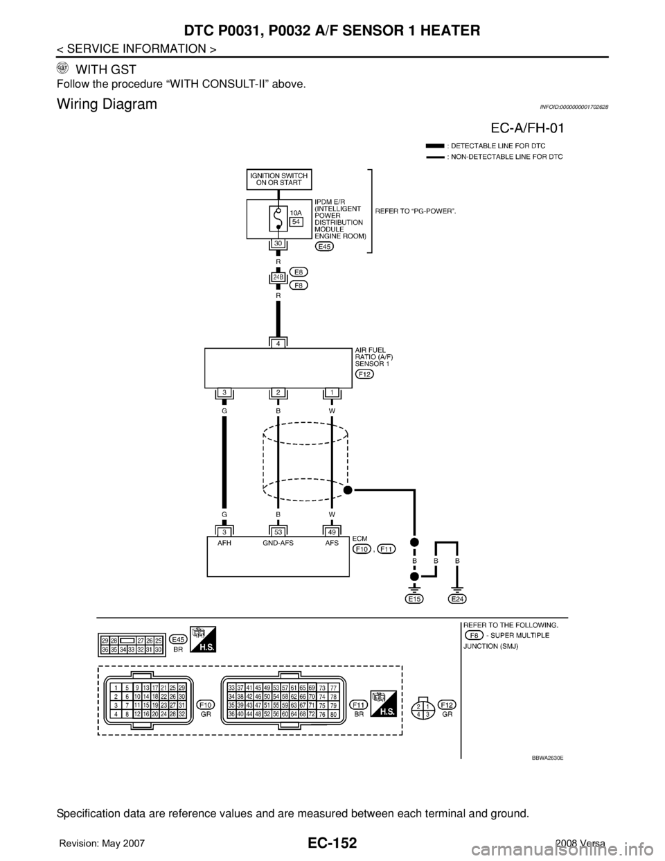
Wiring DiagramINFOID:0000000001702628
Specification data are reference values and are measured between each terminal and ground.
BBWA2630E
Page 1227 of 2771

DTC P0031, P0032 A/F SENSOR 1 HEATER
EC-153
< SERVICE INFORMATION >
C
D
E
F
G
H
I
J
K
L
MA
EC
N
P O
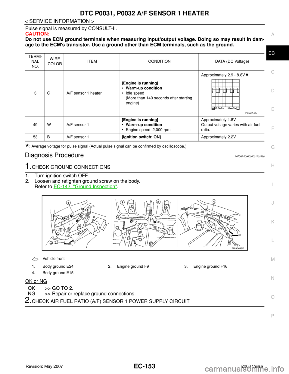
Pulse signal is measured by CONSULT-II.
CAUTION:
Do not use ECM ground terminals when measuring input/output voltage. Doing so may result in dam-
age to the ECM's transistor. Use a ground other than ECM terminals, such as the ground.
: Average voltage for pulse signal (Actual pulse signal can be confirmed by oscilloscope.)
Diagnosis ProcedureINFOID:0000000001702629
1.CHECK GROUND CONNECTIONS
1. Turn ignition switch OFF.
2. Loosen and retighten ground screw on the body.
Refer to EC-142, "
Ground Inspection".
OK or NG
OK >> GO TO 2.
NG >> Repair or replace ground connections.
2.CHECK AIR FUEL RATIO (A/F) SENSOR 1 POWER SUPPLY CIRCUIT
TERMI-
NAL
NO.WIRE
COLORITEM CONDITION DATA (DC Voltage)
3 G A/F sensor 1 heater[Engine is running]
•Warm-up condition
• Idle speed
(More than 140 seconds after starting
engine)Approximately 2.9 - 8.8V
49 W A/F sensor 1[Engine is running]
•Warm-up condition
• Engine speed: 2,000 rpmApproximately 1.8V
Output voltage varies with air fuel
ratio.
53 B A/F sensor 1[Ignition switch: ON]Approximately 2.2V
PBIA8148J
:Vehicle front
1. Body ground E24 2. Engine ground F9 3. Engine ground F16
4. Body ground E15
BBIA0698E