2008 NISSAN LATIO heater
[x] Cancel search: heaterPage 1574 of 2771
 sensor 1 is a planar one-cell limit current sen-
sor.")
EC-500
< SERVICE INFORMATION >
DTC P2A00 A/F SENSOR 1
DTC P2A00 A/F SENSOR 1
Component DescriptionINFOID:0000000001703041
The air fuel ratio (A/F) sensor 1 is a planar one-cell limit current sen-
sor. The sensor element of the A/F sensor 1 is composed an elec-
trode layer, which transports ions. It has a heater in the element.
The sensor is capable of precise measurement = 1, but also in the
lean and rich range. Together with its control electronics, the sensor
outputs a clear, continuous signal throughout a wide range.
The exhaust gas components diffuse through the diffusion layer at
the sensor cell. An electrode layer is applied voltage, and this current
relative oxygen density in lean. Also this current relative hydrocar-
bon density in rich.
Therefore, the A/F sensor 1 is able to indicate air fuel ratio by this
electrode layer of current. In addition, a heater is integrated in the
sensor to ensure the required operating temperature of about 800°C
(1,472°F).
CONSULT-II Reference Value in Data Monitor ModeINFOID:0000000001703042
Specification data are reference values.
On Board Diagnosis LogicINFOID:0000000001703043
To judge the malfunction, the A/F signal computed by ECM from the A/F sensor 1 signal is monitored not to be
shifted to LEAN side or RICH side.
DTC Confirmation ProcedureINFOID:0000000001703044
NOTE:
If DTC Confirmation Procedure has been previously conducted, always turn ignition switch OFF and wait at
least 10 seconds before conducting the next test.
TESTING CONDITION:
Before performing the following procedure, confirm that battery voltage is more than 11V at idle.
WITH CONSULT-II
1. Start engine and warm it up to normal operating temperature.
2. Turn ignition switch OFF and wait at least 10 seconds.
PBIB3353E
PBIB3354E
MONITOR ITEM CONDITION SPECIFICATION
A/F SEN1 (B1) • Engine: After warming upMaintaining engine speed at
2,000 rpmFluctuates around 2.2V
DTC No. Trouble diagnosis name DTC detecting condition Possible Cause
P2A00
2A00Air fuel ratio (A/F) sensor 1
circuit range/performance• The output voltage computed by ECM from the
A/F sensor 1 signal is shifted to the lean side for
a specified period.
• The A/F signal computed by ECM from the A/F
sensor 1 signal is shifted to the rich side for a
specified period.• Air fuel ratio (A/F) sensor 1
• Air fuel ratio (A/F) sensor 1 heater
• Fuel pressure
• Fuel injector
• Intake air leaks
Page 1577 of 2771
DTC P2A00 A/F SENSOR 1
EC-503
< SERVICE INFORMATION >
C
D
E
F
G
H
I
J
K
L
MA
EC
N
P O
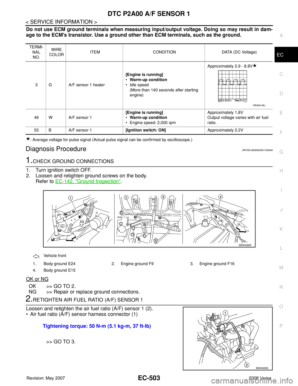
Do not use ECM ground terminals when measuring input/output voltage. Doing so may result in dam-
age to the ECM's transistor. Use a ground other than ECM terminals, such as the ground.
: Average voltage for pulse signal (Actual pulse signal can be confirmed by oscilloscope.)
Diagnosis ProcedureINFOID:0000000001703046
1.CHECK GROUND CONNECTIONS
1. Turn ignition switch OFF.
2. Loosen and retighten ground screws on the body.
Refer to EC-142, "
Ground Inspection".
OK or NG
OK >> GO TO 2.
NG >> Repair or replace ground connections.
2.RETIGHTEN AIR FUEL RATIO (A/F) SENSOR 1
Loosen and retighten the air fuel ratio (A/F) sensor 1 (2).
• Air fuel ratio (A/F) sensor harness connector (1)
>> GO TO 3.
TERMI-
NAL
NO.WIRE
COLORITEM CONDITION DATA (DC Voltage)
3 G A/F sensor 1 heater[Engine is running]
•Warm-up condition
• Idle speed
(More than 140 seconds after starting
engine)Approximately 2.9 - 8.8V
49 W A/F sensor 1[Engine is running]
•Warm-up condition
• Engine speed: 2,000 rpmApproximately 1.8V
Output voltage varies with air fuel
ratio.
53 B A/F sensor 1[Ignition switch: ON]Approximately 2.2V
PBIA8148J
:Vehicle front
1. Body ground E24 2. Engine ground F9 3. Engine ground F16
4. Body ground E15
BBIA0698E
Tightening torque: 50 N-m (5.1 kg-m, 37 ft-lb)
BBIA0699E
Page 1579 of 2771

DTC P2A00 A/F SENSOR 1
EC-505
< SERVICE INFORMATION >
C
D
E
F
G
H
I
J
K
L
MA
EC
N
P O
2. Check voltage between A/F sensor 1 terminal 4 and ground with
CONSULT-II or tester.
OK or NG
OK >> GO TO 8.
NG >> GO TO 7.
7.DETECT MALFUNCTIONING PART
Check the following.
• Harness connectors E8, F8
• Harness for open or short between A/F sensor 1 and fuse
>> Repair or replace harness or connectors.
8.CHECK A/F SENSOR 1 INPUT SIGNAL CIRCUIT FOR OPEN AND SHORT
1. Turn ignition switch OFF.
2. Disconnect ECM harness connector.
3. Check harness continuity between the following terminals. Refer to Wiring Diagram.
4. Check harness continuity between ECM terminals 49, 53 or A/F sensor 1 terminals 1, 2 and ground.
Refer to Wiring Diagram.
5. Also check harness for short to power.
OK or NG
OK >> GO TO 9.
NG >> Repair open circuit or short to ground or short to power in harness or connectors.
9.CHECK A/F SENSOR 1 HEATER
Refer to EC-154, "
Component Inspection".
OK or NG
OK >> GO TO 10.
NG >> GO TO 11.
10.CHECK INTERMITTENT INCIDENT
Perform EC-136
.
OK or NG
OK >> GO TO 11.
NG >> Repair or replace.
11 .REPLACE AIR FUEL RATIO (A/F) SENSOR 1
Replace air fuel ratio (A/F) sensor 1.
CAUTION:
• Discard any air fuel ratio (A/F) sensor which has been dropped from a height of more than 0.5 m
(19.7 in) onto a hard surface such as a concrete floor; use a new one. Voltage: Battery voltage
PBIB3308E
A/F sensor 1 terminal ECM terminal
149
253
Continuity should exist.
Continuity should not exist.
Page 1593 of 2771

ELECTRICAL LOAD SIGNAL
EC-519
< SERVICE INFORMATION >
C
D
E
F
G
H
I
J
K
L
MA
EC
N
P O
ELECTRICAL LOAD SIGNAL
CONSULT-II Reference Value in Data Monitor ModeINFOID:0000000001703057
Specification data are reference values.
Diagnosis ProcedureINFOID:0000000001703058
1.CHECK LOAD SIGNAL CIRCUIT OVERALL FUNCITION-I
1. Turn ignition switch ON.
2. Check “LOAD SIGNAL” in “DATA MONITOR” mode with CON-
SULT-II under the following conditions.
OK or NG
OK >> GO TO 2.
NG >> GO TO 4.
2.CHECK LOAD SIGNAL CIRCUIT OVERALL FUNCTION-II
Check “LOAD SIGNAL” in “DATA MONITOR” mode with CONSULT-
II under the following conditions.
OK or NG
OK >> GO TO 3.
NG >> GO TO 5.
3.CHECK HEATER FAN SIGNAL CIRCUIT OVERALL FUNCTION
Check “HEATER FAN SW” in “DATA MONITOR” mode with CON-
SULT-II under the following conditions.
OK or NG
OK >>INSPECTION END.
NG >> GO TO 6.
4.CHECK HEADLAMP SYSTEM
Refer to LT- 4
or LT- 2 5.
MONITOR ITEM CONDITION SPECIFICATION
LOAD SIGNAL • Ignition switch: ONRear window defogger switch is ON and/or lighting
switch is in 2nd position.ON
Rear window defogger switch is OFF and lighting switch
is OFF.OFF
HEATER FAN SW • Ignition switch: ONHeater fan: Operating. ON
Heater fan: Not operating. OFF
Condition LOAD SIGNAL
Lighting switch: ON at 2nd position ON
Lighting switch: OFF OFF
PBIB0103E
Condition LOAD SIGNAL
Rear window defogger switch: ON ON
Rear window defogger switch: OFF OFF
PBIB0103E
Condition LOAD SIGNAL
Heater fan control switch: ON ON
Heater fan control switch: OFF OFF
PBIB1995E
Page 1594 of 2771

EC-520
< SERVICE INFORMATION >
ELECTRICAL LOAD SIGNAL
>>INSPECTION END
5.CHECK REAR WINDOW DEFOGGER SYSTEM
Refer to GW-49
.
>>INSPECTION END
6.CHECK HEATER FAN CONTROL SYSTEM
Refer to MTC-22
.
>>INSPECTION END
Page 1622 of 2771

SERVICE DATA AND SPECIFICATIONS (SDS)
Fuel PressureINFOID:0000000001703081
Idle Speed and Ignition TimingINFOID:0000000001703082
*:")
EC-548
< SERVICE INFORMATION >
SERVICE DATA AND SPECIFICATIONS (SDS)
SERVICE DATA AND SPECIFICATIONS (SDS)
Fuel PressureINFOID:0000000001703081
Idle Speed and Ignition TimingINFOID:0000000001703082
*: Under the following conditions:
• Air conditioner switch: OFF
• Electric load: OFF (Lights, heater fan & rear window defogger)
• Steering wheel: Kept in straight-ahead position
Calculated Load ValueINFOID:0000000001703083
Mass Air Flow SensorINFOID:0000000001703084
*: Engine is warmed up to normal operating temperature and running under no load.
Intake Air Temperature SensorINFOID:0000000001703085
Engine Coolant Temperature SensorINFOID:0000000001703086
Fuel pressure at idle
Approximately 350 kPa (3.57 kg/cm2, 51 psi)
Target idle speedA/T No load* (in P or N position)
700 ± 50 rpm CVT No load* (In P or N position)
M/T No load* (in Neutral position)
Air conditioner: ONA/T In P or N position
850 rpm or more CVT In P or N position
M/T In Neutral position
Ignition timingA/T In P or N position
13 ± 5° BTDC CVT In P or N position
M/T In Neutral position
Calculated load value% (Using CONSULT-II or GST)
At idle10 - 35
At 2,500 rpm10 - 35
Supply voltageBattery voltage (11 - 14V)
Output voltage at idle1.0 - 1.3*V
Mass air flow (Using CONSULT-II or GST)1.0 - 4.0 g·m/sec at idle*
2.0 - 10.0 g·m/sec at 2,500 rpm*
Temperature °C (°F) Resistance kΩ
25 (77)1.800 - 2.200
Temperature °C (°F) Resistance kΩ
20 (68)2.1 - 2.9
50 (122)0.68 - 1.00
90 (194)0.236 - 0.260
Page 1623 of 2771

EC-549
< SERVICE INFORMATION >
C
D
E
F
G
H
I
J
K
L
MA
EC
N
P O
Air Fuel Ratio (A/F) Sensor 1 HeaterINFOID:0000000001703087
Heated Oxygen sensor 2 HeaterINFOID:000")
SERVICE DATA AND SPECIFICATIONS (SDS)
EC-549
< SERVICE INFORMATION >
C
D
E
F
G
H
I
J
K
L
MA
EC
N
P O
Air Fuel Ratio (A/F) Sensor 1 HeaterINFOID:0000000001703087
Heated Oxygen sensor 2 HeaterINFOID:0000000001703088
Crankshaft Position Sensor (POS)INFOID:0000000001703089
Refer to EC-301, "Component Inspection".
Camshaft Position Sensor (PHASE)INFOID:0000000001703090
Refer to EC-307, "Component Inspection".
Throttle Control MotorINFOID:0000000001703091
Fuel InjectorINFOID:0000000001703092
Fuel PumpINFOID:0000000001703093
Resistance [at 25°C (77°F)] 1.8 - 2.44Ω
Resistance [at 25°C (77°F)] 3.4 - 4.4Ω
Resistance [at 25°C (77°F)] Approximately 1 - 15Ω
Resistance [at 10 - 60°C (50 - 140°F)] 11.4 - 14.5Ω
Resistance [at 25°C (77°F)] Approximately 0.2 - 5.0Ω
Page 1750 of 2771

ENGINE ASSEMBLY
EM-73
< SERVICE INFORMATION >
C
D
E
F
G
H
I
J
K
L
MA
EM
N
P O
• Use either 2-pole lift type or separate type lift as best you can. If board-on type is used for unavoid-
able reasons, support at the rear axle jacking point with a transmission jack or similar tool before
starting work, in preparation for the backward shift of center of gravity.
• For supporting points for lifting and jacking point at rear axle, refer to GI-38, "
Garage Jack and
Safety Stand and 2-Pole Lift".
REMOVAL
Remove the engine and the transaxle assembly from the vehicle downward. Separate the engine and the tran-
saxle.
1. Remove engine undercover
2. Drain engine coolant from radiator. Refer to CO-8, "
Changing Engine Coolant".
CAUTION:
• Perform this step when the engine is cold.
• Do not spill engine coolant on drive belt.
3. Remove front fender protector (RH and LH); Refer to EI-23
.
4. Remove exhaust front tube; Refer to EX-4
.
5. Remove drive shafts (LH and RH) from steering knuckle. Refer to FAX-8
.
6. Remove transaxle joint bolts which pierce at oil pan (upper) lower rear side. Refer to AT-226
(A/T models),
CVT-178
(CVT) or MT-16 (M/T models).
7. Remove rear torque rod (1).
NOTE:
A/T model shown CVT and M/T models similar.
8. Remove hood assembly. Refer to BL-13
.
9. Remove cowl top cover and cowl top extension assembly. Refer to EI-21
.
10. Release fuel pressure. Refer to EC-78, "
Fuel Pressure Check".
11. Remove battery and battery tray; Refer to SC-4
.
12. Remove drive belt; Refer to EM-13, "
Component".
13. Remove air duct and air cleaner case assembly; Refer to EM-16
.
14. Remove cooling fan assembly.
15. Remove radiator hose (upper and lower). Refer to CO-11
.
16. Disconnect A/T, CVT fluid cooler hoses. Refer to CO-11
.
17. Disconnect all connections of engine harness around the engine mounting insulator (LH), and then tem-
porarily secure the engine harness into the engine side.
CAUTION:
Protect connectors using a resin bag to protect against foreign materials during the operation.
18. Disconnect fuel feed hose at engine side. Refer to EM-33, "
Component".
19. Disconnect heater hoses, and install plugs them to prevent engine coolant from draining. Refer to CO-19,
"Component".
20. Disconnect control cable from transaxle. Refer to CVT-167
(CVT) or AT-203 (A/T), MT-13 (MT).
21. Remove ground cable at transaxle side.
22. Remove ground cable between front cover and vehicle.
23. Remove generator. Refer to SC-20
.
24. Remove A/C compressor with piping connected from the engine. Temporarily secure it on the vehicle side
with a rope to avoid putting load on it. Refer to MTC-78, "
Removal and Installation of Compressor".
25. Remove the intake manifold to prevent the hanging chain from interfering. Refer to EM-18, "
Component".
LBIA0460E